RTG8708300123Remote Control
Bosch Termotecnologia S.A.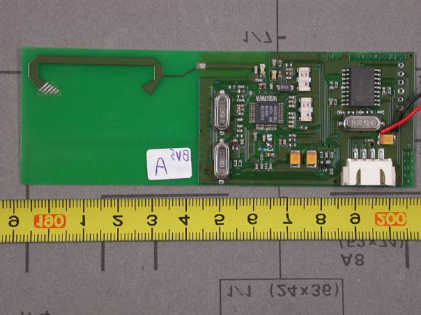
Click to zoom
Application Details
- Equipment Class
- DXT - Part 15 Low Power Transceiver, Rx Verified
- Date of Grant
- Feb 04, 2004
- Application Purpose
- Original Equipment
- Date of Application
- Feb 04, 2004
- Equipment Note
- Remote Control
- Frequency Range
- 903.14400000 - 903.14400000
- Company
- Bosch Termotecnologia S.A.
- Country
- Portugal
Documents & Files
Document Text
Text extracted from the exhibit documents filed with the FCC. Open a document above to read the original.
Users Manual
Water heaters for use with Natural and L.P.G. GWH-635-ES Temperature Modulated with Electronic Ignition Suitable for heating potable water only - Not approved for space heating purposes (Intended for variable flow applications with multiple tapping points) GWH-635-ES-N GWH-635-ES-L 6 720 607 072 (16 January) JS PRO TANKLESS Warning: If the information in this manual is not followed exactly. A fire or explosion may result causing property damage, personal injury or death. Do not store or use gasoline or other flammable vapor and liquids in the vicinity of this or any other appliance. Improper installation, adjustment, alteration, service or maintenance can cause injury or property damage. Refer to this manual. For assistance or additional information consult a qualified installer, service agency or the gas supplier. In the Commonwealth of Massachusetts this product must be installed by a licensed plumber or gas fitter. Upon completion of the installation, these instructions should be handed to the user of the appliance for future reference. What to do if you smell gas • Close gas valve. Open windows. • Do not try to light any appliance • Do not touch any electrical switch; do not use any phone in your building • If you cannot reach your gas supplier, call the fire department. • Immediately call your gas supplier from a neighbor’s phone. Follow the gas supplier’s instructions • Installation and service must be performed by a qualified installer, service agency or the gas supplier. 6 720 607 072 (16 January) 2 Index Index 1 Warning 2 2 Appliance details 4 2.1 Features 4 2.2 GWH-635-ES Specifications (Technical data) 4 2.3 Dimensions and Minimum installation clearances 6 2.4 General rules to follow for safe operation 7 2.5 Proper location for installing your heater 7 2.6 Clearances 8 2.7 Mounting installation 8 2.8 Combustion air requirements 8 2.9 Venting 9 2.9.1 Venting options 12 2.10 Gas piping & connections 15 2.11 Gas line sizing 17 2.12 Measuring gas pressure 17 2.13 Water connections 18 2.14 Electrical connections 20 2.15 Operating instructions 20 2.16 For your safety read before operating your water heater 20 2.17 Lighting and operating instructions 20 3 Operation instructions 22 3.1 Power 22 3.2 Temperature selection 22 3.3 New remote control registration 24 3.4 Operation 24 3.5 Reset button 24 3.6 Program button 24 3.7 Locked condition 25 4 Maintenance and service 25 5 Troubleshooting 25 6 Electrical diagram 28 7 GWH-635-ES Functional scheme 29 8 Interior components diagram and parts list 30 8.1 Interior components 30 8.2 Components diagram 31 8.3 Parts list 32 9 Special adjustment for measuring and adjusting CO 2 levels 33 9.1 Adjusting the unit 33 9.1.1 CO 2 measuring port 33 9.1.2 Selecting adjustment mode 33 10 Protecting the environment 35 11 Fifteen Year Limited Warranty 36 1Warning Featuring Electronic Ignition and Power Venting For your safety Do not store or use gasoline or other flammable, combustible or corrosive vapors and liquids in the vicinity of this or any other appliance. Warning: If the information in this manual is not followed exactly. A fire or explosion may result causing property damage, personal injury or death. Warning: Improper installation, adjustment, alteration, service or maintenance can cause injury or property damage. Refer to this manual. For assistance or additional information consult a qualified installer, service agency or the gas supplier. Upon completion of the installation, these instructions should be handed to the user of the appliance for future reference. Warning: Carefully plan where you install the heater. Correct combustion air supply and flue pipe installation are very important. If a gas appliance is not installed correctly, fatal accidents can result from lack of air, carbon monoxide poisoning or fire. Warning: Exhaust gas must be vented to outside using proper vent material suitable for category III vent systems and temperatures up to 480°F. Vent and combustion air connector piping must be sealed gas-tight to prevent possibility of flue gas spillage, carbon monoxide emissions and risk of fire, resulting in severe personal injury or death. Warning: Place the heater in a location where water leaks will do NO DAMAGE to adjacent areas or lower floors. 6 720 607 072 (16 January) Warning 3 What to do if you smell gas • Close gas valve. Open windows. • Do not try to light any appliance. • Do not touch any electrical switch; do not use any phone in your building. • Immediately call your gas supplier from a neighbor’s phone. Follow the gas supplier’s instructions. • If you cannot reach your gas supplier, call the fire department. • Installation and service must be performed by a qualified installer, service agency or the gas supplier. Fig. 1 Fig. 2 Warning: Field wiring connections and electrical grounding must comply with local codes, or in the absence of local codes, with the latest edition of the National Electric Code, ANSI/NFPA 70, or in Canada, all electrical wiring must comply with the local codes and the Canadian Electrical Code, CSA C22.1 Part 1. Warning: Shock hazard line voltage is present. Before servicing the water heater, turn off the electrical power to the water heater at the main disconnect or circuit breaker. Failure to do so could result in severe personal injury or death. Warning: The heater must be disconnected from the gas supply piping system during any pressure testing of that system at test pressures equal to or more than 0.5 psig. 6 720 607 072 (16 January) 4 Appliance details 2 Appliance details 2.1 Features Parts • Touch Pad interface control • High power pre-mix compact burner with low Nox emissions • Modulating Gas Valve with constant gas:air ratio control • Modulating water valve for improved comfort and temperature control. Safety • Flame sensor (ionization) rod • Overheat sensor • Temperature limiter • Fan speed monitoring. High Quality Materials for Long Working Life • Copper heat exchanger • Ceramic Burn…
Text truncated - open the document above for the full version.
Cover Letter(s)
Request for Confidentiality 04 February 2004 PHOENIX TEST-LAB GmbH Königswinkel 10 D32825 Blomberg Germany RE: Certification Application FCC ID: RTG8708300123 Please be advised that the following information is to be held confidential on behalf of Vulcano Termodomésticos S.A.: • Schematics • Block Diagram • Technical Description The application contains technical information which Vulcano Termodomésticos S.A deems to be trade secrets and proprietary. If made public, the information might be used to the disadvantage of the applicant in the market place. Thank you for your attention to this matter.
Cover Letter(s)
EMV-PrüfzentrumEMI/EMC-Testcenter Coordinates: Äussere Frühlingstrasse 45 ü D-94315 Straubing Telefon (0 94 21) 55 22-0 Telefax (0 94 21) 55 22-99 [email protected] ü http://www.senton.de Senton GmbH ü Äussere Frühlingstrasse 45 ü D-94315 Straubing Phoenix Test-Lab TCB 03 Februar 2004 In reference to FCC ID RTG8708300123 Justification for Part 15 Unlicensed Modular Transmitter Approval according to DA 00-1407 1. Own RF Shielding Complied, see EUT internal Photographs. No shieldings required 2. Buffered Modulation inputs Complied, see schematic diagrams 3. Own power supply regulation Complied, voltage regulated power supply on board, see schematic diagram 4. Antenna requirements Complied, integrated antenna 5. Test in stand-alone configuration Complied, see test report for details. Cable lengths typical to actual use. 6. Own FCC ID Complied, the exterior label will be „Contains FCC ID RTG8708300123 “ 7. Not applicable, the unit operates under Section 15.249 of the FCC Rules 8. RF Exposure requirements Not applicable since the unit operates under section 15.249 of the FCC Rules, the reference guide contains general installation and operation instructions. Johann Roidt Senton GmbH
External Photos
FCC ID: RTG8708300123 Photos of EUT Page 1 of 2 FCC ID: RTG8708300123 Photos of EUT Page 2 of 2
ID Label/Location Info
Contains Transmitter Module FCC ID: RTG8708300123
Internal Photos
FCC ID: RTG8708300123 Photos of EUT Page 1 of 2 FCC ID: RTG8708300123 Photos of EUT Page 2 of 2
Test Report
EMV-PrüfzentrumEMI/EMC-Testcenter FCC-ID: Test Report No. 58002-30555-2 Page 1 of 16 Pages Straubing, 12 September 2003 T E S T - R E P O R T No. 58002-30555-2 for CELSIUS Remote Controller, Base Unit Applicant: A. J. Fonseca Lda Test Specification: FCC Code of Federal Regulations, CFR 47, Part 15, Sections 15.209 and 15.249 Note: The test data of this report relate only to the individual item which has been tested. This report shall not be reproduced except in full extent without the written approval of the testing laboratory. EMV-PrüfzentrumEMI/EMC-Testcenter FCC-ID: Test Report No. 58002-30555-2 Page 2 of 16 Pages Table of Contents 1. Administrative Data....................................................................................3 2. Identification of Test Laboratory.................................................................4 3. Summary....................................................................................................5 4. Operation Mode and Configuration of EUT................................................6 5. Measuring Methods...................................................................................7 5.1. Field Strength of Emissions, Prescans in a fully-anechoic Room...................................................................................................7 5.2. Radiated Emission Measurement at Open Area Test Site..................9 6. Photographs Taken During Testing.........................................................10 7. List of Measurements...............................................................................12 8. Referenced Regulations..........................................................................15 Charts taken during testing...............................................................................16 EMV-PrüfzentrumEMI/EMC-Testcenter FCC-ID: Test Report No. 58002-30555-2 Page 3 of 16 Pages 1. Administrative Data Test item (EUT) Type designation CELSIUS Version of EUT: Serial number(s): BB Type of equipment: Remote Controller, Base Unit Parts/accessories: --- FCC-ID: Technical data Frequency range: 902 - 928 MHZ Operational frequencies: --- Type of modulation: FM Pulse frequency: N/A Pulse width: N/A Class of emission: 140K0F3D Antenna: Integrated Power supply: 2 x 1.5 V Alakaline Batteries Applicant: (full address) A.J. Fonseca Lda Rua Herois de Mucaba, 32 4470-056 Gueifaes Portugal Contract identification: Verbal Contact person: Mr. Leal Duarte Manufacturer: Applicant Application details Receipt of EUT: 25 August 2003 Date of test: 01 September 2003 Note: EMV-PrüfzentrumEMI/EMC-Testcenter FCC-ID: Test Report No. 58002-30555-2 Page 4 of 16 Pages 2. Identification of Test Laboratory Details of the Test Laboratory Company name: Senton GmbH EMI/EMC Test Center Address: Aeussere Fruehlingstrasse 45 D-94315 Straubing Germany Laboratory Accreditation: DAR-Registration No. TTI-P-G 062/94-01 FCC Test Site registration number 90926 Industry Canada Test site registration: IC 3050 Name for contact purposes: Mr. Johann Roidt Phone: (+49) (0)9421 5522-0 Fax: (+49) (0)9421 5522-99 EMV-PrüfzentrumEMI/EMC-Testcenter FCC-ID: Test Report No. 58002-30555-2 Page 5 of 16 Pages 3. Summary Summary of test results The tested sample complies with the requirements set forth in the Code of Regulations CFR 47, Part 15, Sections 15.207, 15.209 and 15.249 of the Federal Communication Commission (FCC) and the Radio Standards Specification RSS-210 Issue 5, Section 7 (Category I Receiver) of Industry Canada (IC). Personnel involved in this report Laboratory Manager: Mr. Johann Roidt Responsible for testing: Mr. Johann Roidt Responsible for test report: Mr. Johann Roidt EMV-PrüfzentrumEMI/EMC-Testcenter FCC-ID: Test Report No. 58002-30555-2 Page 6 of 16 Pages 4. Operation Mode and Configuration of EUT Operation Mode 1) Continuous TX Configuration of EUT Not applicable List of ports and cables Port Description Classification 1 Cable type Cable length No ports List of devices connected to EUT Item Description Type Designation Serial no. or ID Manufacturer Not applicable 1 Ports shall be classified as ac power, dc power or signal/control port EMV-PrüfzentrumEMI/EMC-Testcenter FCC-ID: Test Report No. 58002-30555-2 Page 7 of 16 Pages 5. Measuring Methods 5.1. Field Strength of Emissions, Prescans in a fully-anechoic Room Rules and Specifications: Sections 15.109, 15.209, 15.245 Guide: ANSI C63.4 1997 Measurement Procedure: Radiated emissions are measured over the frequency range from 30 MHz to maximum frequency as specified in section 15.33. Measurements are made in both the horizontal and vertical planes of polarization in a fully anechoic room using a spectrum analyzer with the detector function set to peak and resolution as well as video bandwidth set to 100 kHz (below 1 GHz) or 1 MHz (above 1 GHz). All tests are performed at a test-distance of 3 meters. Hand-held or body-worn devices are rotated through three orthogonal axes to determine which attitude and configuration produces the highest emission relative to the limit and therefore shall be used for final testing. During the tests the EUT is rotated all around to find the maximum levels of emissions. The cables and equipment were placed and moved within the range of position likely to find their maximum emissions. EUT Fully anechoic chamber 3 m test distance Spectrum Analyzer EMV-PrüfzentrumEMI/EMC-Testcenter FCC-ID: Test Report No. 58002-30555-2 Page 8 of 16 Pages Test instruments used: No. Type Model Serial Number Manufacturer 01 Spectrum Analyzer FSP 30 100063 Rohde & Schwarz 02 Preamplifier CPA9231A 3393 Schaffner 03 Biconical antenna HK 116 829708/006 Rohde & Schwarz 04 Log. periodic antenna 3147 9112-1054 EMCO 05 Horn antenna 3115 9508-4553 EMCO 06 Horn antenna 3160-03 9112-1003 Emco 07 Horn antenna 3160-04 9112-1001 Emco 08 Horn antenna 3160-05 9112-1001 Emco 09 Horn antenna 3160-06 9112-1001 Emco 10 Horn antenna 3160-07 9112-1008 Emco 11 Horn antenna 3160-08 9112-1002 Emco …
Text truncated - open the document above for the full version.
Test Setup Photos
EMV-PrüfzentrumEMI/EMC-Testcenter FCC-ID: Test Report No. 58002-30555-2 Page 11 of 16 Pages Test setup for radiated emission measurement (fully anechoic room)
Contact Information
Applicant
Pedro Abrantes(Product certification responsable)
Technical Contact
Senton GmbHJohann Roidt
[email protected]+49 9421 55 22 13
Aeussere Fruehlingstrasse 45 · Straubing · Germany
Non-Technical Contact
Senton GmbHJohann Roidt
[email protected]+49 9421 55 22 13
Test Firm
TUV SUD Product Service GmbH PS-EMC-STRRainer Heller
Technical Specifications
| # | Rule Parts | Frequency Range | Power Output |
|---|---|---|---|
| 1 | 15C | 903.144 MHz - 903.144 MHz | - |
Other Applications from Bosch Termotecnologia S.A.

RTG8708300283
Apr 28, 2009Remote Control Transceiver for Bosch Water Heater
Equipment Class
DXX - Part 15 Low Power Communication Device Transmitter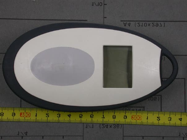
RTG8708300122
Feb 10, 2004Remote Control
Equipment Class
DXT - Part 15 Low Power Transceiver, Rx Verified