RTG8708300283Remote Control Transceiver for Bosch Water Heater
Bosch Termotecnologia S.A.
Click to zoom
Application Details
- Equipment Class
- DXX - Part 15 Low Power Communication Device Transmitter
- Date of Grant
- Apr 28, 2009
- Application Purpose
- Original Equipment
- Date of Application
- Apr 28, 2009
- Equipment Note
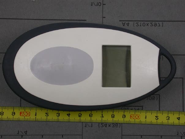
- Remote Control Transceiver for Bosch Water Heater
- Frequency Range
- 903.09200000 - 903.09200000
- Company
- Bosch Termotecnologia S.A.
- Country
- Portugal
Documents & Files
Document Text
Text extracted from the exhibit documents filed with the FCC. Open a document above to read the original.
Users Manual
www.tuv.com Report No. 02421838 001 Appendix 9: User Manual FCCID : RTG8708300283 (Total: 21 pages, include this page) Bosch Remote Control for: GWH 635 ES/635 ESO/250SX/250SXO/2400E/ 2400EO/2400ES/2700ES/715ES/C800ES/C920ES/C920ESC 6720606990-00.1JS 6 720 680 209 (2009/02) US 6720680209-0902_(New Remote control).fm Page 1 Monday, January 19, 2009 8:58 AM 2 Contents 6 720 680 209 Contents 1FCC Declaration of conformity 3 2Remote control data 4 3Remote control Kit 4 3.1Parts supplied 4 4Remote control installation for: GWH-635-ES/GWH-635- ESO/250SX/250SXO/2400E/ 2400EO 5 4.1Remote control transceiver PCB installation 5 4.2Remote control activation 8 4.2.1 AF board 8 4.2.2 SU board 9 5Remote control installation for: GWH C920 ES/ESC / GWH C800 ES/GWH 715 ES/ GWH 2700 ES/ GWH2400ES 10 5.1Remote control transceiver PCB installation 10 5.2Remote control activation11 6Remote control 13 6.1Description of the LCD 13 6.2Hot water temperature adjustment by remote control 13 6.3"Program" button on the remote control 13 6.4"Priority" function 15 6.5Error messages 16 7Troubleshooting 16 7.1Replacing batteries 16 7.2Cleaning 16 7.3Troubleshooting 16 8Notes 19 6720680209-0902_(New Remote control).fm Page 2 Monday, January 19, 2009 8:58 AM 3 Safety instructions 6 720 680 209 Safety instructions BRead the following instructions very carefully to ensure correct operation. BFollow safety instructions. 1FCC Declaration of conformity This device meets the requirements of FCC Directives. This device complies with Part 15 of the FCC rules. Operation is subject to the following two conditions: (1) This device may not cause harmful interference, and (2) this device must accept any interference received, including interference that may cause undesired operation. Caution: Any changes or modifications not expressly approved by the party responsible for compliance could void the user’s authority to operate the equipment. Caution: the remote control is water resistant and can also be used in the shower . Nevertheless, it is not waterproof and must not be immersed in water, for instance in the bathtub . Caution: The remote control can be used only in the following countries: United States of America and Canada. 6720680209-0902_(New Remote control).fm Page 3 Monday, January 19, 2009 8:58 AM 4 Remote control data 6 720 680 209 2Remote control data Remote control for temperature adjustment of Bosch water heaters. Technical Data: Further Information: 3Remote control Kit 3.1Parts supplied Fig. 1Parts 1Remote control 2Remote control transceiver PCB 3Support block (used only for GWH 635 ES/GWH 635 ESO/250SX/ 250SXO) 4PCB connection cable Battery power supply Alkaline AA LR 6 2 x 1.5V Frequency903 MHz Type of protection IP X6 User range 98 ft (30 m) Remote control Up to 6 remote controls can be programmed for one single appliance. 6720680209-0902_(New Remote control).fm Page 4 Monday, January 19, 2009 8:58 AM 5 Remote control installation 6 720 680 209 4Remote control installation for: GWH 635 ES/GWH 635 ESO/250SX/250SXO/2400E/2400EO 4.1Remote control trans- ceiver PCB installation Pre-installation preparation BDisconnect power supply to heater. BRemove plastic decals on front panel. BLoosen two Philips head screws located behind plastic decals. BLift front cover upward and remove. Fig. 2 BRemove the 5 screws on the front retaining bar (see Fig. 2, pos. 1 and 2) being careful not to damage the foam sealant material on it. BRemove control unit auxiliary cover (Fig. 2, pos. 4). BRemove the two electrical strip connectors inside the auxiliary cover (Fig. see diagram below) and then loosen the 110V power supply cord retaining nut located underneath the heater. Once loosened, the power cord can be pulled up through the heater to provide sufficient slack. Electrical strip connecto rs BAt the ignition electrodes, pull off the 2 yellow igniter wires that come from Warning: For safety reasons, disconnect the power supply to the water heater before performing installation. Once auxiliary cover is off, pull off the two electrical strip connectors from the board. Once off, the wiring harness can be removed from the case by pulling their rubber seals outward. 6720680209-0902_(New Remote control).fm Page 5 Monday, January 19, 2009 8:58 AM 6 Remote control installation 6 720 680 209 the top of the control unit (Fig. 2, pos. 3). Then pull the complete control unit forward and out of the heater, pull up the power supply cord further if more slack is needed. BWhile holding the unit in one hand or resting it on a flat surface, remove the front cover of the control unit by removing the 4 screws. Remote control transceiver PCB installation BOpen control unit top cover (Fig. 3, pos. 1). BRemove the protective paper (Fig. 3, pos. 2) from one face of the support and attach it to the main PCB as shown in Fig. 4. Fig. 3 BRemove the other protective paper and attach the remote control PCB as shown in Fig. 5. Fig. 4 Support correct position BUse the supplied cable to connect between the main PCB and the remote control PCB as shown in Fig. 5. Fig. 5 6720680209-0902_(New Remote control).fm Page 6 Monday, January 19, 2009 8:58 AM 7 Remote control installation 6 720 680 209 BReplace the control unit cover with the 4 Philips head screws (Fig. 3, pos. 1). BSlide control unit back into heater. BPlug 2 yellow electrode wires from the top of the control unit back onto the ignition electrodes. Ensure all connections are secure and tight (Fig. 2, pos. 3). BPull end of power cord to take up excess slack and tighten retaining nut on the bottom of the heater. BReinstall the two electrical strip connectors onto the PCB. The larger connector connects to the lower connection on the PCB. Reseat the rubber seals for both connectors. BReplace the control unit auxiliary cover. (Fig. 2, pos. 4). BReplace front retaining bar using 5 Phillips head screws. (Fig. 2, pos 1). 4.2Remote control activation The remote control activation instructions vary based on the version of contr…
Text truncated - open the document above for the full version.
ID Label/Location Info
www.tuv.com Appendix 4 Prüfbericht - Nr.: Test Report No. 02421838 001 Seite 1 von 1 Page 1 of 1
Internal Photos
www.tuv.com Appendix 3 Prüfbericht - Nr.: Test Report No. 02421838 001 Seite 1 von 2 Page 1 of 2 www.tuv.com Appendix 3 Prüfbericht - Nr.: Test Report No. 02421838 001 Seite 2 von 2 Page 2 of 2
Test Report
www.tuv.com Test Report No: 02421838 001 Date: 29.04.2009 Page 2 of 12 Test Summary Radiated Spurious Emissions – Receiving mode Result : Pass Radiated Emission of Carrier Frequency – Transmitting mode Result : Pass Spurious Radiated Emission – Transmitting mode Result : Pass 20dB Bandwidth Measurement – Transmitting mode Result : Pass www.tuv.com Test Report No: 02421838 001 Date: 29.04.2009 Page 3 of 12 Table of Content Page Cover Page .............................................................................................. ..1 Test Summary .............................................................................................................2 List of Test and Measurement Instruments ..............................................................4 Product Information ....................................................................................................5 Manufacturer declaration..................................................................................................................... 5 Submitted Documents.......................................................................................................................... 6 Test Methodology .......................................................................................................7 Radiated Spurious Emission Test - Receiving mod Section 15.109(a) ............8 Radiated Emission of Carrier frequency Section 15.249 ......................................9 Radiated Spurious Emission Section 15.249 ..........................................10 20dB Bandwidth Measurement Section 15.215(c) .....................................12 Appendix 1 – Test setup Photos Appendix 2 – External Photos Appendix 3 – Internal Photos Appendix 4 – FCC ID Label & Label Location Diagram Appendix 5 – Block Diagram & Operational Description Appendix 6 – Specification of EUT Appendix 7 – Schematic Diagram Appendix 8 – Bill of Material Appendix 9 – User Manual www.tuv.com Test Report No: 02421838 001 Date: 29.04.2009 Page 4 of 12 List of Test and Measurement Instruments HCL Technologies, Chennai List of Test and Measurements Equipment Manufacturer Type S/N Calibration Due Date EMI Receiver Rohde & Schwarz ESIB26 100360 21.05.2009 Ultra Broad Band Antenna Rohde & Schwarz HL562 100287 19.01.2010 Horn Antenna Rohde & Schwarz ETS3115 29269 09.05.2009 SAMEER-Center for Electromagnetics, Chennai List of Test and Measurements Equipment Manufacturer Type S/N Calibration Due Date EMI Receiver Rohde & Schwarz ESIB7 100319 06.03.2010 Loop Antenna ETS Lingdren 6507 1484 12.10.2009 Testing Facilities 1) HCL Technologies Limited 73-74, Ground Floor, South Phase, Ambattur Estate, Ambattur Chennai – 600058 India 2) SAMEER-Center for Electromagnetics C.I.T.Campus, Taramani, 2nd Main Road, Chennai – 600113 India www.tuv.com Test Report No: 02421838 001 Date: 29.04.2009 Page 5 of 12 Product Information The EUT is a transceiver of remote control unit which used with Bosch Termotecnologia SA water heaters. The Remote control system enables a user to remotely control the temperature of the water of the water heater by the remote control unit. The user can also view some information about the status of the heater on the remote control unit. Manufacturer declaration Operating Frequency 903.092 MHz Antenna Monopole on Printed Circuit Board Modulation FSK with +/- 40 kHz deviation Receiver type Dual conversion superheterodyne Intermediate Frequency ( IF) First IF: 10.7 MHz, 180 kHz bandwidth Second IF: 700 kHz Receiver sensitivity -100dBm Modulation data 4800 baud, Manchester coded binary data RF Communication protocol Half-duplex, Packed Manchester coded binary data with limited collision avoidance. Power supply 1.5 V AA battery x 2 , nominal voltage : 3.0 V Different carrier power levels No Software Version TuVTest_me0x.14 Equipment classification Fixed use Mobile use Portable use AC Power port(s) No Independent Operation Modes Transmitter Receiver www.tuv.com Test Report No: 02421838 001 Date: 29.04.2009 Page 6 of 12 Submitted Documents Circuit Diagram Bill of material User Manual Rating Label Remark ---- Additional accessory used for testing None www.tuv.com Test Report No: 02421838 001 Date: 29.04.2009 Page 7 of 12 Test Methodology Radiated Emission The radiated emission measurement was performed according to the procedures in ANSI C63.4-2003. The equipment under test (EUT) was placed at the middle of the 80 cm high turntable, and the EUT is 3 or 10 meters far from the measuring antenna. The turntable was rotated 360゚ for obtaining the maximum emission. The height of the measuring antennas were scanned between 1m and 4m, and the antenna rotated to repeat the measurements for both the horizontal and vertical antenna polarizations. The measurement above 1000MHz was performed by horn antenna. The measurement below 30MHz was performed by loop antenna, maximum emission was obtained by two antenna polarizations of loop faced and sided to the EUT. Test Setup : EUT 3m EMI Receiver / Spectrum Analyzer Turntable Ground Plane Semi-anechoic Chamber www.tuv.com Test Report No: 02421838 001 Date: 29.04.2009 Page 8 of 12 Radiated Spurious Emission Test - Receiving mode Section 15.109(a) RESULT: Pass Test Specification : FCC Part 15 Section 15.109 Test Method : ANSI C63.4-2003 Measurement Location : Semi Anechoic Chamber Supply Voltage : Battery operated, 3.0V DC Measuring Frequency Range : 30MHz – 5GHz Measuring Distance : 3m Detector : QP for frequency below 1GHz, Average for frequency above 1GHz Mode of Operation Receiving Test Result: Antenna Polarization Spurious Emission (MHz) Emission Level (dBμV/m) Limit (dBμV/m) Margin (dB) 1806.4 37.8 54.0 16.2 6985.2 33.7 54.0 20.3 V 11341.6 32.6 54.0 21.4 1806.4 48.0 54.0 6.0 2709.2 29.4 54.0 24.6 H 11790.4 19.8 54.0 34.2 Limit: Frequency of Emission (MHz) Field Strength (μV/m) Field Strength (dBμV/m) 30-88 100 40.00 88-216 150 43.52 216-960 200 46.00 Above 960 500 54.00 www.tuv.com Test Report No: 02421838 001 …
Text truncated - open the document above for the full version.
Test Report
www.tuv.com Test Report No: 02421838 001 Date: 29.04.2009 Page 2 of 12 Test Summary Radiated Spurious Emissions – Receiving mode Result : Pass Radiated Emission of Carrier Frequency – Transmitting mode Result : Pass Spurious Radiated Emission – Transmitting mode Result : Pass 20dB Bandwidth Measurement – Transmitting mode Result : Pass www.tuv.com Test Report No: 02421838 001 Date: 29.04.2009 Page 3 of 12 Table of Content Page Cover Page .............................................................................................. ..1 Test Summary .............................................................................................................2 List of Test and Measurement Instruments ..............................................................4 Product Information ....................................................................................................5 Manufacturer declaration..................................................................................................................... 5 Submitted Documents.......................................................................................................................... 6 Test Methodology .......................................................................................................7 Radiated Spurious Emission Test - Receiving mod Section 15.109(a) ............8 Radiated Emission of Carrier frequency Section 15.249 ......................................9 Radiated Spurious Emission Section 15.249 ..........................................10 20dB Bandwidth Measurement Section 15.215(c) .....................................12 Appendix 1 – Test setup Photos Appendix 2 – External Photos Appendix 3 – Internal Photos Appendix 4 – FCC ID Label & Label Location Diagram Appendix 5 – Block Diagram & Operational Description Appendix 6 – Specification of EUT Appendix 7 – Schematic Diagram Appendix 8 – Bill of Material Appendix 9 – User Manual www.tuv.com Test Report No: 02421838 001 Date: 29.04.2009 Page 4 of 12 List of Test and Measurement Instruments HCL Technologies, Chennai List of Test and Measurements Equipment Manufacturer Type S/N Calibration Due Date EMI Receiver Rohde & Schwarz ESIB26 100360 21.05.2009 Ultra Broad Band Antenna Rohde & Schwarz HL562 100287 19.01.2010 Horn Antenna Rohde & Schwarz ETS3115 29269 09.05.2009 SAMEER-Center for Electromagnetics, Chennai List of Test and Measurements Equipment Manufacturer Type S/N Calibration Due Date EMI Receiver Rohde & Schwarz ESIB7 100319 06.03.2010 Loop Antenna ETS Lingdren 6507 1484 12.10.2009 Testing Facilities 1) HCL Technologies Limited 73-74, Ground Floor, South Phase, Ambattur Estate, Ambattur Chennai – 600058 India 2) SAMEER-Center for Electromagnetics C.I.T.Campus, Taramani, 2nd Main Road, Chennai – 600113 India www.tuv.com Test Report No: 02421838 001 Date: 29.04.2009 Page 5 of 12 Product Information The EUT is a transceiver of remote control unit which used with Bosch Termotecnologia SA water heaters. The Remote control system enables a user to remotely control the temperature of the water of the water heater by the remote control unit. The user can also view some information about the status of the heater on the remote control unit. Manufacturer declaration Operating Frequency 903.092 MHz Antenna Monopole on Printed Circuit Board Modulation FSK with +/- 40 kHz deviation Receiver type Dual conversion superheterodyne Intermediate Frequency ( IF) First IF: 10.7 MHz, 180 kHz bandwidth Second IF: 700 kHz Receiver sensitivity -100dBm Modulation data 4800 baud, Manchester coded binary data RF Communication protocol Half-duplex, Packed Manchester coded binary data with limited collision avoidance. Power supply 1.5 V AA battery x 2 , nominal voltage : 3.0 V Different carrier power levels No Software Version TuVTest_me0x.14 Equipment classification Fixed use Mobile use Portable use AC Power port(s) No Independent Operation Modes Transmitter Receiver www.tuv.com Test Report No: 02421838 001 Date: 29.04.2009 Page 6 of 12 Submitted Documents Circuit Diagram Bill of material User Manual Rating Label Remark ---- Additional accessory used for testing None www.tuv.com Test Report No: 02421838 001 Date: 29.04.2009 Page 7 of 12 Test Methodology Radiated Emission The radiated emission measurement was performed according to the procedures in ANSI C63.4-2003. The equipment under test (EUT) was placed at the middle of the 80 cm high turntable, and the EUT is 3 or 10 meters far from the measuring antenna. The turntable was rotated 360゚ for obtaining the maximum emission. The height of the measuring antennas were scanned between 1m and 4m, and the antenna rotated to repeat the measurements for both the horizontal and vertical antenna polarizations. The measurement above 1000MHz was performed by horn antenna. The measurement below 30MHz was performed by loop antenna, maximum emission was obtained by two antenna polarizations of loop faced and sided to the EUT. Test Setup : EUT 3m EMI Receiver / Spectrum Analyzer Turntable Ground Plane Semi-anechoic Chamber www.tuv.com Test Report No: 02421838 001 Date: 29.04.2009 Page 8 of 12 Radiated Spurious Emission Test - Receiving mode Section 15.109(a) RESULT: Pass Test Specification : FCC Part 15 Section 15.109 Test Method : ANSI C63.4-2003 Measurement Location : Semi Anechoic Chamber Supply Voltage : Battery operated, 3.0V DC Measuring Frequency Range : 30MHz – 5GHz Measuring Distance : 3m Detector : QP for frequency below 1GHz, Average for frequency above 1GHz Mode of Operation Receiving Test Result: Antenna Polarization Spurious Emission (MHz) Emission Level (dBμV/m) Limit (dBμV/m) Margin (dB) 1806.4 37.8 54.0 16.2 6985.2 33.7 54.0 20.3 V 11341.6 32.6 54.0 21.4 1806.4 48.0 54.0 6.0 2709.2 29.4 54.0 24.6 H 11790.4 19.8 54.0 34.2 Limit: Frequency of Emission (MHz) Field Strength (μV/m) Field Strength (dBμV/m) 30-88 100 40.00 88-216 150 43.52 216-960 200 46.00 Above 960 500 54.00 www.tuv.com Test Report No: 02421838 001 …
Text truncated - open the document above for the full version.
Test Setup Photos
www.tuv.com Appendix 1 Prüfbericht - Nr.: Test Report No. 02421838 001 Seite 1 von 2 Page 1 of 2 Setup for Radiated Emission Test Setup for Radiated Emission Test www.tuv.com Appendix 1 Prüfbericht - Nr.: Test Report No. 02421838 001 Seite 2 von 2 Page 2 of 2 Setup for Radiated Emission Test
Contact Information
Applicant
Pedro Abrantes(Product certification responsable)
Test Firm
Hong Kong Productivity CouncilIr Angel Wong Yuen-yee
Technical Specifications
| # | Rule Parts | Frequency Range | Power Output |
|---|---|---|---|
| 1 | 15C | 903.092 MHz - 903.092 MHz | - |
Other Applications from Bosch Termotecnologia S.A.
RTG8708300122
Feb 10, 2004Remote Control
Equipment Class
DXT - Part 15 Low Power Transceiver, Rx Verified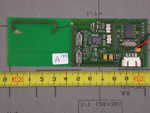
RTG8708300123
Feb 04, 2004Remote Control
Equipment Class
DXT - Part 15 Low Power Transceiver, Rx Verified