RU5AWBFXUBLUETOOTH USB DONGLE
Asia Pacific Microsystems, Inc.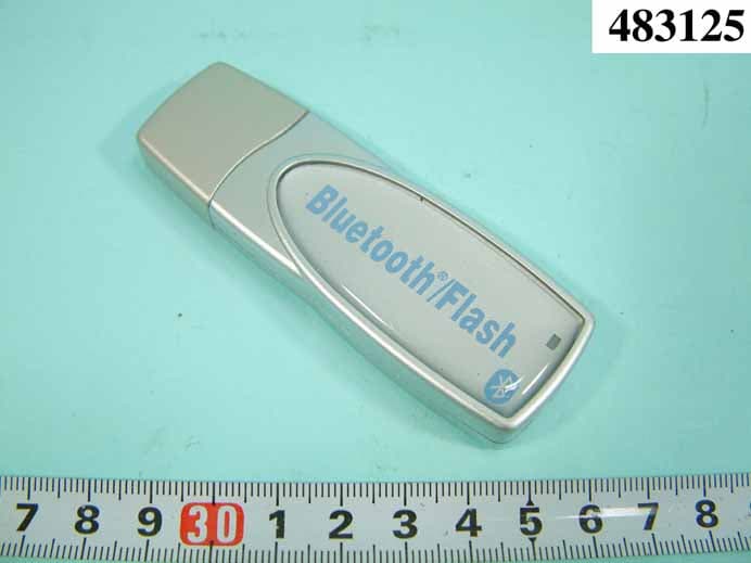
Click to zoom
Application Details
- Equipment Class
- DSS - Part 15 Spread Spectrum Transmitter
- Date of Grant
- Jan 04, 2005
- Application Purpose
- Original Equipment
- Date of Application
- Jan 04, 2005
- Equipment Note
- BLUETOOTH USB DONGLE
- Frequency Range
- 2402.00000000 - 2480.00000000
- Country
- Taiwan
Documents & Files
Document Text
Text extracted from the exhibit documents filed with the FCC. Open a document above to read the original.
Users Manual
IVT BlueSoleil™ User Manual Version: 1.4 This document describes how to use IVT BlueSoleil™. FCC DoC Labeling FEDERAL COMMUNICATIONS COMMISSION This device complies with Part 15 of the FCC Rules. Operation is subject to the following two conditions:(1) this device may not cause harmful interference, and (2) this device must accept any interference received, including interference that may cause undesired operation. NOTE This equipment has been tested and found to comply with the limits for a Class B digital device, pursuant to Part 15 of the FCC Rules. These limits are designed to provide reasonable protection against harmful interference in a residential installation. This equipment generates, uses and can radiated radio frequency energy and, if not installed and used in accordance with the instructions, may cause harmful interference to radio communications. However, there is no guarantee that interference will not occur in a particular installation If this equipment does cause harmful interference to radio or television reception, which can be determined by turning the equipment off and on, the user is encouraged to try to correct the interference by one or more of the following measures: -Reorient or relocate the receiving antenna. -Increase the separation between the equipment and receiver. -Connect the equipment into an outlet on a circuit different from that to which the receiver is connected. -Consult the dealer or an experienced radio/TV technician for help. Changes or modifications not expressly approved by the party responsible for compliance could void the user‘s authority to operate the equipment. The antenna(s) used for this transmitter must not be co-located or operating in conjunction with any other antenna or transmitter This EUT is compliance with SAR for general population /uncontrolled exposure limits in ANSI/IEEE C95.1-1999 and had been tested in accordance with the measurement methods and procedures specified in OET Bulletin 65 Supplement C Prohibition of co-location This device and its antenna(s) must not be co-located or operating in conjunction with any other antenna or transmitter Tested to Comply With FCC Standard FOR HOME OR OFFICE USE Class 2 Bluetooth Pen Drive IVT BlueSoleil™ User Manual Copyright © 2001, IVT Corporation, http://www.ivtcorporation.com All specifications are preliminary and subject to change without notice. 2 Contents 1 BlueSoleil™ Introduction............................................................................ 1 1.1 Profiles .................................................................................................... 1 1.2 New features in BlueSoleil 1.4 ..................................................................... 2 1.3 Features in BlueSoleil 1.2 ........................................................................... 2 2 BlueSoleil™ Basic Operations ..................................................................... 4 2.1 Start BlueSoleil™ ...................................................................................... 4 2.2 Exit BlueSoleil™ ........................................................................................ 4 2.3 BlueSoleil™ Main Window ........................................................................... 5 2.4 Service Window......................................................................................... 8 2.5 What You Need To Do Before Build A Connection ......................................... 10 2.6 Start Or Stop A Bluetooth Service Connection.............................................. 14 3 Bluetooth Security.................................................................................... 16 3.1 Introduction ........................................................................................... 16 3.2 BlueSoleil Security Configuration ............................................................... 17 4 Personal Area Networking........................................................................ 22 4.1 Introduction ........................................................................................... 22 4.2 Communication Between Two Computers.................................................... 23 4.3 Access LAN Through PAN-NAP ................................................................... 29 4.4 Access LAN Through IVT BlueSoleil™.......................................................... 33 4.5 Access Internet through IVT BlueSoleil™..................................................... 35 4.6 PAN Configuration ................................................................................... 36 5 Dial-Up Networking .................................................................................. 38 5.1 Introduction ........................................................................................... 38 5.2 Connect to a Dial-up Gateway from a Computer........................................... 38 5.3 Settings for Dial-up Networking Profile (client side) in Windows98/Me ............. 41 6 Bluetooth Serial Port ................................................................................ 46 6.1 Introduction ........................................................................................... 46 6.2 Connect Two Computers........................................................................... 46 6.3 Use SPP to Print a Document..................................................................... 48 6.4 Use a cellphone to control a computer ........................................................ 48 6.5 SPP Configuration.................................................................................... 50 7 Bluetooth File Transfer............................................................................. 52 7.1 Introduction ........................................................................................... 52 7.2 Transfer files to/from a Computer .............................................................. 52 7.3 FTP Co…
Text truncated - open the document above for the full version.
Users Manual
IVT BlueSoleil™ User Manual Copyright © 2001, IVT Corporation, http://www.ivtcorporation.com All specifications are preliminary and subject to change without notice. 57 Figure 8.1: Right-click My Network Places Figure 8.2: Select Properties on the pop up menu ♦ Click Networking on the Incoming Connections Properties pop-up window. (Figure 8.3) ♦ Choose Internet Protocol (TCP/IP) and click Properties. (Figure 8.4) IVT BlueSoleil™ User Manual Copyright © 2001, IVT Corporation, http://www.ivtcorporation.com All specifications are preliminary and subject to change without notice. 58 Figure 8.3: Incoming Connections Properties Figure 8.4: Choose Internet Protocol (TCP/IP) ♦ Select Specify TCP/IP addresses, and input the two IP addresses. The subnet mask of the two IP addresses should be the same as the subnet of the LAN Computer A belongs to. (Figure 8.5) IVT BlueSoleil™ User Manual Copyright © 2001, IVT Corporation, http://www.ivtcorporation.com All specifications are preliminary and subject to change without notice. 59 Figure 8.5: Input the IP addresses Step 5: Connect to Computer A. 1. Search for Computer A on Computer B. 2. Find the LAP service of Computer A. 3. Right-click the LAP service icon; select Connect on the pop-up menu. (Figure 8.6) Figure 8.6: Select Connect ♦ The Connect BlueSoleil™ LAP Connection window pops up. Input a username and password. (Figure 8.7) ♦ The connection is then established. IVT BlueSoleil™ User Manual Copyright © 2001, IVT Corporation, http://www.ivtcorporation.com All specifications are preliminary and subject to change without notice. 60 Figure 8.7: Input Username and Password Step 6: Computer B can now access the LAN via Computer A. 8.3 Access a LAN via a LAN Access Point This section outlines the steps involved in accessing a LAN through a LAN access point. LAN Access Point A: Computer B Bluetooth access point Notebook/Laptop A Bluetooth Device Windows 2000 IVT BlueSoleil™ Step 1: Connect LAN access point to the Local Area Network. ♦ Set the LAN access point’s name to anything you want. Here it is named LAN Access Point A. ♦ Set LAN Access Point A’s IP address to be in the same range as the other computers in the LAN. Step 2: Insert the Bluetooth Device into the computer. Step 3: Start BlueSoleil™ in the computer. Step 4: Connect to the LAN Access Point A. 1. Find the LAP service of LAN Access Point A 2. Double-click on the LAN Access Point A device icon on IVT BlueSoleil™ User Manual Copyright © 2001, IVT Corporation, http://www.ivtcorporation.com All specifications are preliminary and subject to change without notice. 61 Computer B. 3. Right-click the LAP service icon; select Connect on the pop-up menu. ♦ The Connect BlueSoleil™ LAP Connection window pops up. Input username and password. (Figure 8.8) ♦ The connection is now established. (Figure 8.9) Figure 8.8: Input username and password Figure 8.9: Successful connection to the LAN Access Point Step 5: Access other computers in the LAN. ♦ Now Computer B can access the LAN via LAN Access Point A. 8.4 Settings for LAN Access Profile (client side) in Windows98/Me Before using the LAN Access Profile in Windows98/Me, ensure that a Dial-up Adapter and Windows’s component direct cable connection are installed on the client computer. IVT BlueSoleil™ User Manual Copyright © 2001, IVT Corporation, http://www.ivtcorporation.com All specifications are preliminary and subject to change without notice. 62 See “Section 5.3.1: Check if a Dial-up Adapter is installed”, to check if a Dial up Adapter is installed in your computer. 8.4.1 Check if a Windows Component Direct Cable Connection is installed Step 1: Select Control Panel from the Start | Settings menu, Step 2: Double-click the Add/Remove Programs icon. (Figure 8.10) Figure 8.10: Double-click the Add/Remove Programs icon Step 3: Select the Windows Setup tab in the Add/Remove Programs Properties window. (Figure 8.11) IVT BlueSoleil™ User Manual Copyright © 2001, IVT Corporation, http://www.ivtcorporation.com All specifications are preliminary and subject to change without notice. 63 Figure 8.11: Select Windows Setup tab Step 4: Double-click the Communications item in the Windows Setup component list to check the properties. (Figure 8.12) IVT BlueSoleil™ User Manual Copyright © 2001, IVT Corporation, http://www.ivtcorporation.com All specifications are preliminary and subject to change without notice. 64 Figure 8.12: Double-click Communications item Step 5: Check if Direct Cable Connection is selected. If not, select it and click OK to install a Direct Cable Connection. (Figure 8.13) Figure 8.13: Check if Direct Cable Connection is selected IVT BlueSoleil™ User Manual Copyright © 2001, IVT Corporation, http://www.ivtcorporation.com All specifications are preliminary and subject to change without notice. 65 8.5 Usage of LAN Access Profile (server side) in Windows98/Me 8.5.1 Configure a LAP server in Windows 98/ Me Step 1: Start the LAP service. ♦ See “Section 8.2: Access a Local Area Network (LAN)”, Steps 1 to 5. ♦ If this is the first time the service is started n Windows 98/Me, the Direct Cable Connection window pops up. Step 2: Select Host and click the Next button. (Figure 8.14) Figure 8.14: Direct Cable Connection window Step 3: Select Bluelet NULL Modem (Server) and click Next. (Figure 8.15) IVT BlueSoleil™ User Manual Copyright © 2001, IVT Corporation, http://www.ivtcorporation.com All specifications are preliminary and subject to change without notice. 66 Figure 8.15: Select Bluelet NULL Modem (Server) Step 4: Click the Finish button. (Figure 8.16) Figure 8.16: Click Finish button. Step 5: Finally, the Direct Cable Connection window pops up. It is now possible to connect to the LAP server. No password is required. Figure 8.17: Connection created IVT BlueSoleil™ User Manual Copyright © 2001, IVT Corporation, http://www.ivtcorporation.com All specifications are preliminary and subject to change without notice. 67 Note: The above steps are applicable when con…
Text truncated - open the document above for the full version.
External Photos
REPORT NO. : F483125 SPORTON International Inc. PAGE NUMBER : A1 OF A7 TEL : 886-2-2696-2468 ISSUED DATE : Dec. 20, 2004 FAX : 886-2-2696-2255 APPENDIX A. Photographs of EUT REPORT NO. : F483125 SPORTON International Inc. PAGE NUMBER : A2 OF A7 TEL : 886-2-2696-2468 ISSUED DATE : Dec. 20, 2004 FAX : 886-2-2696-2255
Internal Photos
REPORT NO. : F483125 SPORTON International Inc. PAGE NUMBER : A3 OF A7 TEL : 886-2-2696-2468 ISSUED DATE : Dec. 20, 2004 FAX : 886-2-2696-2255 REPORT NO. : F483125 SPORTON International Inc. PAGE NUMBER : A4 OF A7 TEL : 886-2-2696-2468 ISSUED DATE : Dec. 20, 2004 FAX : 886-2-2696-2255 REPORT NO. : F483125 SPORTON International Inc. PAGE NUMBER : A5 OF A7 TEL : 886-2-2696-2468 ISSUED DATE : Dec. 20, 2004 FAX : 886-2-2696-2255 REPORT NO. : F483125 SPORTON International Inc. PAGE NUMBER : A6 OF A7 TEL : 886-2-2696-2468 ISSUED DATE : Dec. 20, 2004 FAX : 886-2-2696-2255 REPORT NO. : F483125 SPORTON International Inc. PAGE NUMBER : A7 OF A7 TEL : 886-2-2696-2468 ISSUED DATE : Dec. 20, 2004 FAX : 886-2-2696-2255
Test Report
FCC ID: RU5AWBFXU Issued on Dec. 20, 2004 Report No.: F483125 SPORTON International Inc. TEL : 886-2-2696-2468 FAX : 886-2-2696-2255 FCC TEST REPORT CATEGORY : Portable PRODUCT NAME : Bluetooth V1.2 Class 2+ 128MB/ 256MB/ 512MB/ 1GB/ 3GB Flash Drive USB Dongle FCC ID. : RU5AWBFXU FILING TYPE : Certification MODEL NAME : AWBF1U, AWBF2U, AWBF3U, AWBF4U, AWBF5U TRADE NAME APM APPLICANT : Asia Pacific Microsystems, Inc. No. 2, R&D Road 6, Science-Based Industrial Park, Hsinchu, Taiwan, R.O.C. MANUFACTURER : Same as applicant ISSUED BY : SPORTON INTERNATIONAL INC. 6F, No. 106, Sec. 1, Hsin Tai Wu Rd., His Chih, Taipei Hsien, Taiwan, R.O.C. Statements: The test result in this report refers exclusively to the presented test model / sample. Without written approval of SPORTON International Inc., the test report shall not be reproduced except in full. Certificate or Test Report could not be used by the applicant to claim the product endorsement by CNLA, NVLAP or any agency of U.S. government. The test equipment used to perform the test are calibrated and traceable to NML/ROC or NIST/USA. Dr. Alan Lane Vice General Manager Sporton International Inc. Lab Code: 200079-0 FCC ID: RU5AWBFXU Issued on Dec. 20, 2004 Report No.: F483125 SPORTON International Inc. Page No. : i TEL : 886-2-2696-2468 Issued Date : Dec. 20, 2004 FAX : 886-2-2696-2255: Table of Contents History of this test report....................................................................................................................................ii CERTIFICATE OF COMPLIANCE.......................................................................................................................iii 1. General Description of Equipment under Test.............................................................................................1 1.1. Applicant ......................................................................................................................................................................................... 1 1.2. Manufacturer ................................................................................................................................................................................... 1 1.3. Basic Description of Equipment under Test.................................................................................................................................... 1 1.4. Features of Equipment under Test ................................................................................................................................................. 1 1.5. Antenna Description........................................................................................................................................................................ 2 1.6. Table for Carrier Frequencies ......................................................................................................................................................... 2 2. Test Configuration of the Equipment under Test.........................................................................................3 2.1. Connection Diagram of Test System .............................................................................................................................................. 3 2.2. The Test Mode Description............................................................................................................................................................. 3 2.3. Description of Test Supporting Units .............................................................................................................................................. 3 3. General Information of Test............................................................................................................................4 3.1. Test Facility ..................................................................................................................................................................................... 4 3.2. Test Conditions ............................................................................................................................................................................... 4 3.3. Standards for Methods of Measurement......................................................................................................................................... 4 3.4. DoC Statement ............................................................................................................................................................................... 4 3.5. Frequency Range Investigated ....................................................................................................................................................... 4 3.6. Test Distance .................................................................................................................................................................................. 4 3.7. Test Software .................................................................................................................................................................................. 4 4. List of Measurements......................................................................................................................................5 4.1. Summary of the Test Results.......................................................................................................................................................... 5 5. Test Result .......................................................................................................................................................6 5.1. Test of Hopping Channel Bandwidth .............................................................................................................................................. 6 5.2. Test of Hopping Channel Separation...........................................................…
Text truncated - open the document above for the full version.
Test Setup Photos
FRONT VIEW REAR VIEW FRONT VIEW REAR VIEW
Contact Information
Applicant
John Young(Engineer)
Test Firm
SPORTON International IncKathy Lin
Technical Specifications
| # | Rule Parts | Frequency Range | Power Output |
|---|---|---|---|
| 1 | 15C | 2.40 GHz - 2.48 GHz | 2.00 mW |
Other Applications from Asia Pacific Microsystems, Inc.
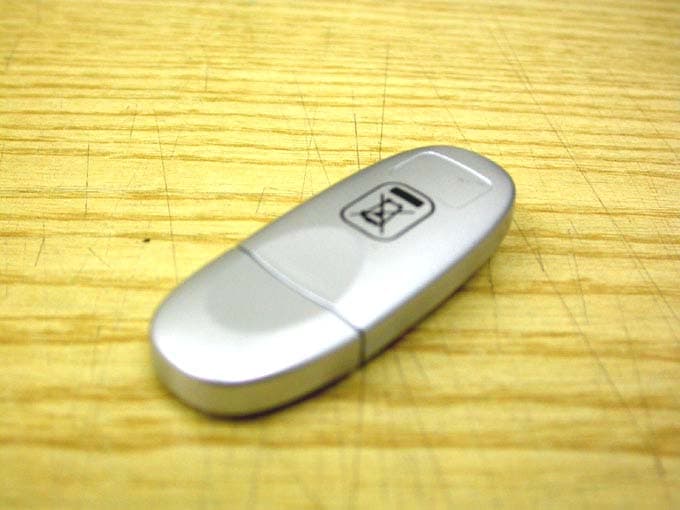
RU5AWBC1E
May 23, 2006Bluetooth V.1.2 Class 1 USB Dongle
Equipment Class
DSS - Part 15 Spread Spectrum Transmitter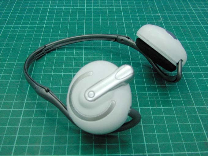
RU5AWBSH3
Apr 27, 2006BLUETOOTH EARPHONE
Equipment Class
DSS - Part 15 Spread Spectrum Transmitter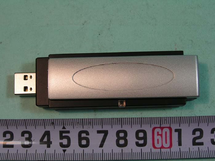
RU5AWGB3U
Mar 29, 2006802.11g WLAN+BlueTooth V1.2 Class 2 USB Dongle
Equipment Class
DTS - Digital Transmission System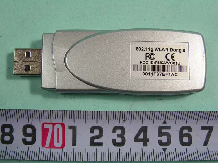
RU5AWG02U
Mar 26, 2006802.11g 54Mbps WLAN 2 USB Dongle
Equipment Class
DTS - Digital Transmission System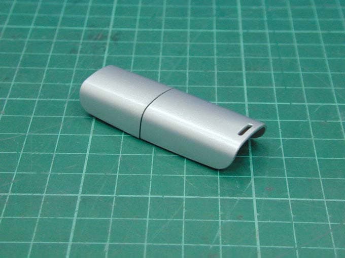
RU5AWBC2E
Dec 19, 2005Bluetooth Dongle
Equipment Class
DSS - Part 15 Spread Spectrum Transmitter