RU5CARETRONWIRELESS TIRE PRESSURE MONITORING SYSTEM
Asia Pacific Microsystems, Inc.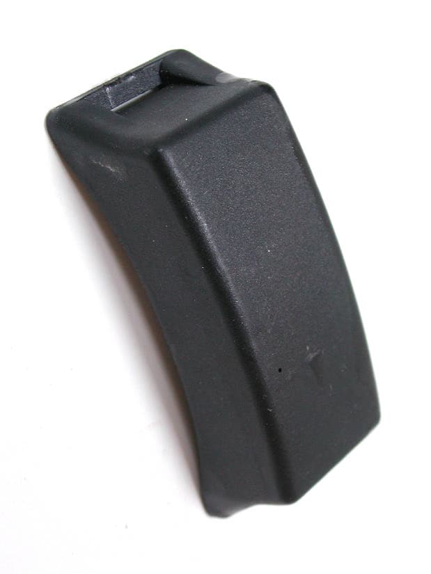
Click to zoom
Application Details
- Equipment Class
- DSC - Part 15 Security/Remote Control Transmitter
- Date of Grant
- Mar 01, 2004
- Application Purpose
- Original Equipment
- Date of Application
- Mar 01, 2004
- Equipment Note
- WIRELESS TIRE PRESSURE MONITORING SYSTEM
- Frequency Range
- 433.50000000 - 434.45000000
- Country
- Taiwan
Documents & Files
Document Text
Text extracted from the exhibit documents filed with the FCC. Open a document above to read the original.
Users Manual
Asia Pacific Microsystems, Inc. ~A Leader In Microsystems Solutions Wireless Tire Pressure Monitoring System, Safety-Plus Owner’s Manual Date: Feb, 2004 Ver.1.0 - 1 - Safety-Plus Advance Tire Safety Tire Pressure Monitoring System User’s Manual Model: WP101L FCC Certification Number: RU5CARETRON Note: Asia Pacific Microsystems, inc. All rights reserved. No part of this documentation may be reproduced in any form or by any means or used to make any directive work (such as translation or transformation) without permission from Asia Pacific Microsystems, Inc. Asia Pacific Microsystems, Inc. reserves the right to revise this documentation and to make changes in content without obligation to Asia Pacific Microsystems, Inc. to provide notification of such revision or change. @2004 Asia Pacific Microsystems, Inc. Asia Pacific Microsystems, Inc. ~A Leader In Microsystems Solutions Wireless Tire Pressure Monitoring System, Safety-Plus Owner’s Manual Date: Feb, 2004 Ver.1.0 - 2 - Table of Contents FCC Notices 3 System Description 3 System Component Parts 3 Let’s Start 4 Installation 4 Receiver 4 Transmitters 4 Installation Procedures 4 Mounting the Tire with Transmitter on Wheel 5 De-Mounting Transmitter/s from Wheel 6 Receiver Description 9 Diagram and Display Indicator 9 The Function of Receiver Button 9 Alerts and Warnings 10 Setup Function 12 Special Setup 14 Technical Specifications 17 Asia Pacific Microsystems, Inc. ~A Leader In Microsystems Solutions Wireless Tire Pressure Monitoring System, Safety-Plus Owner’s Manual Date: Feb, 2004 Ver.1.0 - 3 - FCC Notices FCC Compliance Statement This device complies with part 15 of the FCC Rules. Operation is subject to the following two conditions 1. This device may not cause harmful interferenceand 2. This device must accept any interference receivedincluding interference that may cause undesired operation FCC Warning This equipment has been tested and found to comply with the limits for a Class B digital devicepursuant to Part 15 of the FCC Rules These limits are designed to provide reasonable protection against harmful interference in a residential installation This equipment generatesuses and can radiate radio frequency energy and if not installed and used in accordance with the instructionsmay cause harmful interference to radio communications Howeverthere is no guarantee that interference will not occur in a particular installationIf this equipment does cause harmful interference to radio or television receptionwhich can be determined by turning the equipment off and onthe user is encouraged to try to correct the interference by one or more of the following measures Reorient or relocate the receiving antenna Increase the separation between the equipment and the receiver Connect the equipment into an outlet different from that to which the receiver is connected Consult the dealer or an experienced radio/TV technician for help CAUTIONAny changes or modifications not expressly approved by the party responsible for compliance could void the user’s authority to operate the equipment Safety Notice The product is designed to measure and display the active operative data in tiresand provide the alert or warning when the product detects the pressure or the temperature of tires is irregularitiesThe drivers shall have the responsibility to react with discretion to the alerts or warningsIrregular tire pressure should be remedied at the earliest occasion Asia Pacific Microsystems, Inc. ~A Leader In Microsystems Solutions Wireless Tire Pressure Monitoring System, Safety-Plus Owner’s Manual Date: Feb, 2004 Ver.1.0 - 4 - System Description Safety-Plus is a wireless tire pressure system with sensor/transmitter mounted on each wheel plus a module of Receiver Display placed onto dashboardHigh quality sensors collect real-time tire pressure and temperature data then transmitted by wireless radio to receiver The system monitors the data of tires with digital display on LCD thus driver can be well-posted with most updating info of tire while drivingThe receiver will alert with beep and yellow light while pressure and/or temperature are/is out of normal range System Component Parts Receiver1 Unit Receiver Holder Kit1 Unit Antenna1 Unit DC Cable1 Unit Transmitter4 Units Clamping Strap4 Units Transmitter Mounting Pad8 Units Asia Pacific Microsystems, Inc. ~A Leader In Microsystems Solutions Wireless Tire Pressure Monitoring System, Safety-Plus Owner’s Manual Date: Feb, 2004 Ver.1.0 - 5 - Installation Receiver -- Installation Procedures Stick self-adhere device on the backside of receiver Attach the Holder suction cups on windshield of car Screw Antenna into Receiver Lock the Receiver on the Holder Plug DC Power Cable into Receiver Power Jack and Cigarette Lighter Socket The LCD Display will show “??P” ??P ??P ??P ??P Asia Pacific Microsystems, Inc. ~A Leader In Microsystems Solutions Wireless Tire Pressure Monitoring System, Safety-Plus Owner’s Manual Date: Feb, 2004 Ver.1.0 - 6 - Transmitters -- Installation Procedures The transmitter devices should be installed by qualified technicianThey need to follow installation proceduresIt can ensure that the transmitters are properly installed and undamaged The tools and instruction in this manual are used by the manufacturer’s tire changerIt may not available to you Tools Required l Tire Changing Equipment l Tire Balancing Equipment l Metal Cutter l Torque Wrench Mounting the Tire with Transmitter on Wheel Part IFasten Transmitter in the wheel 1. Pass Clamping Strap through Transmitter 2. Place the Transmitter in the lowest area of the drop center and nearby valve 3. Fasten the Clamping Straptighten to 4N-m (30inch pound) 4. Cut excess Clamping Strap offat approximately one inch from the wormgear Transmitter Valve Position Wormgear Opposite to Transmitter Asia Pacific Microsystems, Inc. ~A Leader In Microsystems Solutions Wireless Tire Pressure Monitoring System, Safety-Plus Owner’s Manual Date: Feb, 2004 Ver.1.0 - 7 - Part II…
Text truncated - open the document above for the full version.
External Photos
External Photos of Tire Pressure Monitoring System 1/4 FCC ID: RU5CARETRON Training Research Co., Ltd., TEL: 886-2-26935155, Fax: 886-2-26934440 External Photos of Tire Pressure Monitoring System 2/4 FCC ID: RU5CARETRON Training Research Co., Ltd., TEL: 886-2-26935155, Fax: 886-2-26934440
ID Label/Location Info
Front-Left IDX X X X X X X X X () ID Safety-Plus Model: WP101L FCC ID: RU5CARETRON This device complies with Part 15 of the FCC Rules See user manual 25mm Made in Taiwan 10mm 20mm 13mm WP101L Label
ID Label/Location Info
LABEL Position:
Internal Photos
Internal Photos of Tire Pressure Monitoring System 3/4 FCC ID: RU5CARETRON Training Research Co., Ltd., TEL: 886-2-26935155, Fax: 886-2-26934440 Internal Photos of Tire Pressure Monitoring System 4/4 FCC ID: RU5CARETRON Training Research Co., Ltd., TEL: 886-2-26935155, Fax: 886-2-26934440
Test Report
Test Report -------------------------------------------------------------------------------1/18 Report No.: A8315058 (TX) Training Research Co., Ltd., TEL: 886-2-26935155, Fax: 886-2-26934440 Report No.A8315058 SpecificationsFCC Part 15.231(e), Certification Test MethodANSI C63.4 1992 ApplicantAsia Pacific Microsystems, Inc. ApplicantNo. 2, R&D Road 6, Science-Based Industrial Park, addressHsinchu, Taiwan Items testedTire Pressure Monitoring System Model WP101L (Sample # A83058) ResultsCompliance (As detailed within this report) Date01/19/2004 (month / day / year) (Sample received) 02/18/2004 (month / day / year) (Test) Prepared byProject Engineer (Jack Tsai) Authorized byGeneral Manager (Frank Tsai) Issue dateFebruary 20, 2004(month / day / year) ModificationsNone Tested by Training Research Co., Ltd. Office atNo. 255, Nan Yang Street, Hsichih, Taipei Hsien 221, Taiwan Chamber at1F, No. 255, Nan Yang Street, Hsichih, Taipei Hsien 221, Taiwan Conditions of issue: (1)This test report shall not be reproduced except in full, without written approval of TRC. And the test result contained within this report only relate to the sample submitted for testing. (2)This test report, measurements made by TRC are traceable to the NIST only Conducted and Radiated Method. ϪʳFCC ID: RU5CARETRON Test Report -------------------------------------------------------------------------------2/18 Report No.: A8315058 (TX) Training Research Co., Ltd., TEL: 886-2-26935155, Fax: 886-2-26934440 Table of Contents CHAPTER 1 GENERAL................................................................................. 3 1.1 I NTRODUCTION..................................................................... 3 1.2 D ESCRIPTION OF EUT .......................................................... 3 1.3 D ESCRIPTION OF SUPPORTEQUIPMENT................................ 3 1.4 T ESTPROCEDURE................................................................. 4 1.5 L OCATION OF THE TESTSITE............................................... 4 1.6 G ENERALTESTCONDITION.................................................. 4 CHAPTER 2 TRANSMITTER DUTY CYCLE MEASUREMENTS........ 5 2.1 T ESTCONDITION AND SETUP............................................... 5 2.2 L IST OF TESTINSTRUMENTS................................................. 5 2.3 T ESTINSTRUMENTSCONFIGURATION.................................. 6 2.4 T ESTRESULT....................................................................... 6 CHAPTER 3 TRANSMITTER BANDWIDTH MEASUREMENTS, FCC PART 15.231(C) ............................................................. 8 3.1 T ESTCONDITION&SETUP................................................... 8 3.2 T ESTRESULT....................................................................... 8 CHAPTER 4 CONDUCTED EMISSIONS MEASUREMENTS .............. 10 4.1 T ESTCONDITION................................................................ 10 4.2 T ESTRESULT..................................................................... 10 CHAPTER 5 RADIATED EMISSIONS MEASUREMENTS .................. 11 5.1 G ENERALCONFIGURATION................................................ 11 5.2 T ESTCONDITION AND SETUP............................................. 11 5.3 L IST OF TESTINSTRUMENTS............................................... 14 5.4 T ESTINSTRUMENTSCONFIGURATION................................ 15 5.5 T ESTRESULT OF RADIATEDEMISSIONS............................. 16 CHAPTER 6 AUTOMATICALLY LIMIT OF TRANSMISSION .......... 17 6.1 T ESTCONDITION AND SETUP............................................. 17 6.2 L IST OFTESTINSTRUMENTS............................................... 17 6.3 T ESTRESULT..................................................................... 18 Test Report -------------------------------------------------------------------------------3/18 Report No.: A8315058 (TX) Training Research Co., Ltd., TEL: 886-2-26935155, Fax: 886-2-26934440 Chapter 1 GENERAL 1.1 Introduction The following measurement report is submitted on behalf of applicant in support of an International Periodic Radiator certification with Part 2 Subpart J and Part 15 Subpart A and C of the Commission's Rules and Regulations. 1.2 Description of EUT Product Name:Wireless Tire Pressure Monitoring System Model : WP101L FCC ID:RU5CARETRON Frequency Range :433MHz ~ 434MHz Power Type:Powered by 3V battery (BR2335 * 1) The fundamental frequency of transmitter emitted is due to a setting of the EUT. There are security codes for avoiding the possibility of duplicating codes in adjacent systems. The coding must be matching with the companion receiver. While testing the EUT was adjusted at a position, which transmits the maximum emission. 1.3 Description of Support Equipment In order to construct the minimum testing, following equipment were used as the support units. Tadial Tubeless:PIRELLI Model No.:P6000 Type:195/50 R 15 82 T Tread: 1 Rayon 2 Steel + Nylon Sidewall: 1 Rayon Test Report -------------------------------------------------------------------------------4/18 Report No.: A8315058 (TX) Training Research Co., Ltd., TEL: 886-2-26935155, Fax: 886-2-26934440 1.4 Test Procedure All measurements contained in this report were performed according to the techniques described in measurement procedure of ANSI C63.4 1992 section 13 1.5 Location of the Test Site The radiated emissions measurements required by the rules were performed on the three-meter,Anechoic Chamber (FCC Registration Number: 93906)maintained by Training Research Co., Ltd. 1F, No. 255, Nan Yang Street, Hsi-chih, Taipei Hsien 221, Taiwan, R.O.C. Complete description and measurement data have been placed on file with the commission. The conducted power line emissions tests and other test items were performed in a anechoic chamber also located at Training Research Co., Ltd. 1F, No. 255, Nan Yang Street, Hsi-chih, Taipei Hsien 221, Taiwan, R.O.C.Training Research Co., Ltd.is listed by the FCC as a facility available to do measurement work for othe…
Text truncated - open the document above for the full version.
Test Setup Photos
Test Setup Photos ------------------------------------------------------------------------- 1/1 FCC ID: RU5CARETRON Training Research Co., Ltd., TEL: 886-2-26935155, Fax: 886-2-26934440 Radiated Test Setup Placement: The Test configuration of Front view The Test configuration of Rear view
Contact Information
Applicant
John Young(Engineer)
Test Firm
Training Research Co., LtdJack Tsai
Technical Specifications
| # | Rule Parts | Frequency Range | Power Output |
|---|---|---|---|
| 1 | 15.231(e) | 433.5 MHz - 434.45 MHz | - |
Other Applications from Asia Pacific Microsystems, Inc.
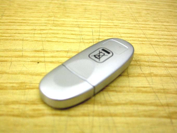
RU5AWBC1E
May 23, 2006Bluetooth V.1.2 Class 1 USB Dongle
Equipment Class
DSS - Part 15 Spread Spectrum Transmitter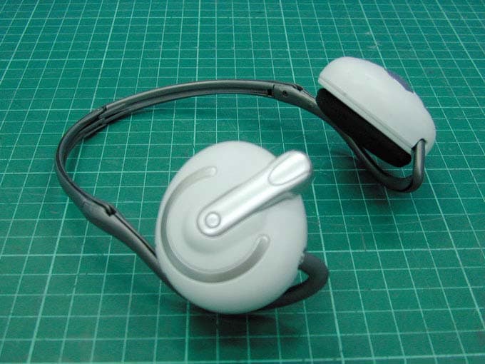
RU5AWBSH3
Apr 27, 2006BLUETOOTH EARPHONE
Equipment Class
DSS - Part 15 Spread Spectrum Transmitter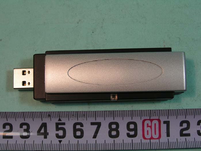
RU5AWGB3U
Mar 29, 2006802.11g WLAN+BlueTooth V1.2 Class 2 USB Dongle
Equipment Class
DTS - Digital Transmission System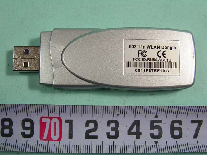
RU5AWG02U
Mar 26, 2006802.11g 54Mbps WLAN 2 USB Dongle
Equipment Class
DTS - Digital Transmission System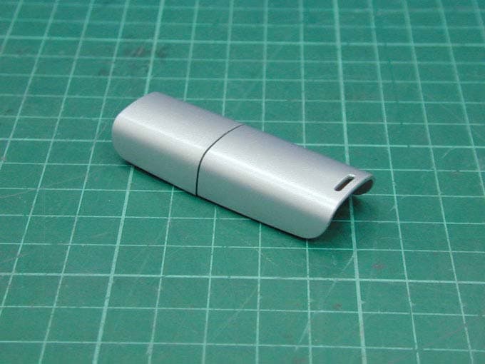
RU5AWBC2E
Dec 19, 2005Bluetooth Dongle
Equipment Class
DSS - Part 15 Spread Spectrum Transmitter