RV7-SC10504.9 GHz, 802.11 Based, Fixed Wireless Node
Trilliant Networks, Inc.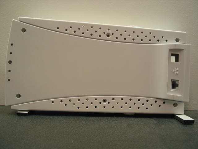
Click to zoom
Application Details
- Equipment Class
- TNB - Licensed Non-Broadcast Station Transmitter
- Date of Grant
- Jan 16, 2006
- Application Purpose
- Original Equipment
- Date of Application
- Jan 16, 2006
- Equipment Note
- 4.9 GHz, 802.11 Based, Fixed Wireless Node
- Frequency Range
- 4950.00000000 - 4980.00000000
- Company
- Trilliant Networks, Inc.
- Country
- United States
Documents & Files
Document Text
Text extracted from the exhibit documents filed with the FCC. Open a document above to read the original.
Users Manual
SKYPILOT NETWORKS CONFIDENTIAL AND PROPRIETARY Page SKYPILOT NETWORKS CONFIDENTIAL AND PROPRIETARY 1 User Guide CPE (SC1050) Version 1.1 December 8, 2005 SKYPILOT NETWORKS CONFIDENTIAL AND PROPRIETARY Page SKYPILOT NETWORKS CONFIDENTIAL AND PROPRIETARY 2 User Guide .......................................................................................................................... 1 CPE (SC1050)..................................................................................................................... 1 1 Introduction.................................................................................................................3 1.1 Outdoor CPE ....................................................................................................... 4 1.2 Indoor CPE.......................................................................................................... 5 2 Network Architecture.................................................................................................. 6 2.1 Link Establishment ............................................................................................. 6 2.2 Bandwidth Allocation ......................................................................................... 6 2.3 Networking ......................................................................................................... 7 3 Installation................................................................................................................... 8 3.1 Indoor CPE.......................................................................................................... 8 3.1.1 Mounting..................................................................................................... 8 3.1.2 Cabling ...................................................................................................... 10 3.2 Outdoor CPE ..................................................................................................... 11 3.2.1 Mounting................................................................................................... 11 3.2.2 Cabling ...................................................................................................... 12 4 Configuration ............................................................................................................ 13 4.1 SC1050 Configuration ...................................................................................... 13 4.1.1 IP Address Management ........................................................................... 13 4.1.2 Ethernet Port Control ................................................................................ 13 4.1.3 Subscriber Data Rates ............................................................................... 13 5 CLI ............................................................................................................................ 14 6 SNMP........................................................................................................................ 15 SKYPILOT NETWORKS CONFIDENTIAL AND PROPRIETARY Page SKYPILOT NETWORKS CONFIDENTIAL AND PROPRIETARY 3 1 Introduction The SkyPilot CPE (SC1050) provides a subscriber interface to a SkyPilot wireless network. The SkyPilot CPE connects either to a SkyPilot Seed (SD1050) or directly to a SkyPilot Gateway (GW1050) device. The SkyPilot CPE operates in the public safety 4.9 GHz band and comes in Indoor and Outdoor variants. The Indoor and Outdoor SkyPilot CPE differ only in the external mechanical packaging. The Indoor CPE is housed in an attractive plastic package that may be installed in a home or office environment. The Outdoor CPE utilizes a fully environmentally sealed housing that supports extended temperature range operation. The combination of the SkyPilot wireless network elements provides a high capable and flexible system. The system and CPE offer: • High Capacity and Long Range OFDM technology, a large link budget and modulation rates of 6-54Mbps, provide reliable Non-LOS operation and market leading capacity. • Meshing The system offers the flexibility of subscriber CPE (SC1050) connection directly to a SkyPilot Gateway (GW1050) or via an intermediary Seed (SD1050), resulting in vastly increased coverage when compared to typical point-to-multipoint systems. • Standards Based The SkyPilot system is based very closely on the 802.11 standard and utilizes commercial chipsets. SkyPilot has implemented significant enhancements that provide range and performance advantages. • Easy Installation The SkyPilot Indoor CPE allows for very simple, end-user install. The compact, environmentally hardened Outdoor CPE is easily installed on a rooftop or under eave. • Networking The SkyPilot system implements an intelligent, Ethernet switching network, with a 10500bT bridge interface provided by the Gateway and CPE. Subscriber rate control and traffic prioritization QoS mechanisms are supported, along with optional VLANs. In addition, there is support for configurable protocol filtering and Access Control Lists (ACL). • Security AES link encryption and complete node authentication with optional support for full MD5 certificates. • Network Management Both node types are fully manageable via SNMPv2c and a Command Line Interface (CLI). Static or DHCP IP address allocation is supported. SKYPILOT NETWORKS CONFIDENTIAL AND PROPRIETARY Page SKYPILOT NETWORKS CONFIDENTIAL AND PROPRIETARY 4 1.1 Outdoor CPE The Outdoor CPE is a fully integrated, environmentally hardened device providing the interface between a wireless SkyPilot network and the local subscriber. The subscriber connection is via a single 10/100bT Ethernet port. The CPE connects to the SkyPilot network via a single, optimized wireless link. The SkyPilot Outdoor CPE houses a single high gain panel antenna providing 30° horizontal coverage and a 9° vertical angle, along with all RF and digital circuitry. The Outdoor CPE utilizes Power over Et…
Text truncated - open the document above for the full version.
Cover Letter(s)
1 Chris Harvey From:Claire Hoque [[email protected]] Sent:Monday, January 16, 2006 5:39 PM To: Chris Harvey; Chris Harvey -TCB Cc:Chuck Cowden Subject:answer: Skypilot Network Inc., FCC ID: RV7-SC1050, Assessment NO.: AN05T5363, Notice#1 TuneUp Procedure.pdf (74 KB) Theory Of Operation.pdf (162 K... 05U3795-2B FCC PT. 90Y Report ... Hi Chris, Here are the answers. 1. Sections 5.2 & 7.4.1 of the test report and the form 731 indicate the frequency of operation as 4894-4990MHz. The remainder of the application has the frequency of operation as 4950-4980 MHz (center of low and high channels). Please correct this discrepancy. <answer>The frequency band should be 4940-4990 MHz. pls see revised report. 2. Additionally, there is a typo of the measurement frequency in the test report section 5.5. Please correct this typo. <answer>pls see revised report. 3. The MPE calculation in the test report used a value of 16dBi for the antenna gain, where the antenna specification indicates a 16.5dBi antenna gain. Although this will not show non-compliance since the recommended separation in the manual is 40cm and the calculation showed that the safe distance is 20cm (or less), please correct this discrepancy and recalculate the MPE power density. <answer>16.5dBi is correct for FCC ID: RV7-SC1050, while 16dBi is correct for RV7-GW-SD1050, and we did submit the correct antenna spec. with 16.5dBi for this application. 4. FCC 90.1215 indicates that "high power point-to-point or point-to-multipoint operation (both fixed and temporary-fixed rapid deployment) may employ transmitting antennas with directional gain up to 26 dBi without any corresponding reduction in the transmitter power or spectral density". The test report has indicated that there is no reduction of power using the 16.5dBi antenna (7.5dBi greater than 9dBi) but has not indicated that these devices will be operated only as Fixed or Temporary-Fixed Rapid Deployment use devices. The installation guide and design of these devices indicate indoor operation, describing a desk or window mount for the Indoor unit. Please explain how these devices fit into the category of Fixed devices (typically the FCC includes the term Fixed-mounted on Outdoor-permanent structures in their requirements). <answer>all of Skypilot's units are meant to be fixed and permanently mounted. The protocols establish links on a point-to-point basis and there are no differences between the operation at 5.8 GHz versus 4.9 GHz, aside from the freq change. 5. Please provide a necessary bandwidth indication and emission type in the form of an emission designator with justification (form 731 and report did not have this information). <answer>The necessary bandwidth is 18.4MHz based upon 99% BW and the emission is designor is 18M4G1D. 6. The name of the Theory of Operation exhibit contains the term tune-up, but no tune- up procedure has been provided. Please provide a tune-up procedure exhibit. Additionally, please provide the DC voltages and currents for the final amplification stages required ffor Licensed Devices per FCC 2.1033(c). <answer>pls see revised theory of operation and tune-up procedure. 2 7. The Pt. 90 report and test procedure does not define the Peak Power in terms of RMS equivalent. Please confirm that the Peak Power Output measured has been measured as a conducted emission over any interval of continuous transmission calibrated in terms of an RMS-equivalent voltage in accordance with FCC 90.1215. <answer>confirmed, pls see revised report. Thanks, Claire -----Original Message----- From: Compliance Certification Services [mailto:[email protected]] Sent: Wednesday, December 21, 2005 8:20 AM To: Michael Heckrotte Cc: Chris Harvey Subject: Skypilot Network Inc., FCC ID: RV7-SC1050, Assessment NO.: AN05T5363, Notice# 1 Michael, you are listed as the technical contact for the above referenced TCB application. The review of this application has raised several issues that need to be addressed before the review can be completed. 1. Sections 5.2 & 7.4.1 of the test report and the form 731 indicate the frequency of operation as 4894-4990MHz. The remainder of the application has the frequency of operation as 4950-4980 MHz (center of low and high channels). Please correct this discrepancy. 2. Additionally, there is a typo of the measurement frequency in the test report section 5.5. Please correct this typo. 3. The MPE calculation in the test report used a value of 16dBi for the antenna gain, where the antenna specification indicates a 16.5dBi antenna gain. Although this will not show non-compliance since the recommended separation in the manual is 40cm and the calculation showed that the safe distance is 20cm (or less), please correct this discrepancy and recalculate the MPE power density. 4. FCC 90.1215 indicates that "high power point-to-point or point-to-multipoint operation (both fixed and temporary-fixed rapid deployment) may employ transmitting antennas with directional gain up to 26 dBi without any corresponding reduction in the transmitter power or spectral density". The test report has indicated that there is no reduction of power using the 16.5dBi antenna (7.5dBi greater than 9dBi) but has not indicated that these devices will be operated only as Fixed or Temporary-Fixed Rapid Deployment use devices. The installation guide and design of these devices indicate indoor operation, describing a desk or window mount for the Indoor unit. Please explain how these devices fit into the category of Fixed devices (typically the FCC includes the term Fixed-mounted on Outdoor-permanent structures in their requirements). 5. Please provide a necessary bandwidth indication and emission type in the form of an emission designator with justification (form 731 and report did not have this information). 6. The name of the Theory of Operation exhibit contains the term tune-up, but no tune- up procedure has been provided. Please provide a tune-up procedure exhibit. Additionally, please p…
Text truncated - open the document above for the full version.
ID Label/Location Info
PROPOSED FCC ID LABEL AND LOCATION Indoor Unit SKYPILOT NETWORK INC. FCC ID: RV7-SC1050 FC ID LABEL LOCATION Outdoor Unit
Parts List/Tune Up Info
SKYPILOT NETWORKS CONFIDENTIAL AND PROPRIETARY Page 1 of 1 SKYPILOT NETWORKS CONFIDENTIAL AND PROPRIETARY SKYPILOT NETWORKS, INC 4.9 GHz Product Tune-Up Procedure SKYPILOT NETWORKS CONFIDENTIAL AND PROPRIETARY Page 2 of 2 SKYPILOT NETWORKS CONFIDENTIAL AND PROPRIETARY 1 Tune-Up Procedure The power and frequency of operation for both Gateway and CPE are set to pre-determined values via firmware control. The system operates at a pre-configured frequency selected by the operator. The firmware controls radio, attenuator and amplifier operation and limits the operator to only use those frequencies and power limits allowed by local compliance regulations. No operator action is required to establish equipment operation aside from channel selection within the allowed frequency band. SkyPilot’s link optimization algorithm utilizes packet loss criteria to then determine the best modulation type to use for the selected channel, however power levels are always fixed to the pre-determined levels during the optimization routine and subsequent unit operation.
Parts List/Tune Up Info
CPE Patch Antenna Specifications 500-00257-01 Electrical Parameter Spec Gain 16.5 dBi Beam Width Azimuth 30 deg Elevation 9 deg Mechanical Parameter Spec Dimensions 10.0” (L) x 4.5” (W) x 0.005” (T)
Test Report
FCC CFR47 PART 90 SUBPART Y CERTIFICATION TEST REPORT FOR 4.9 GHZ, 802.11 BASED, FIXED WIRELESS NODE MODEL NUMBER: SKYCONNECTOR INDOOR SC1050 AND SKYCONNECTOR OUTDOOR SC1050 FCC ID: RV7-SC1050 REPORT NUMBER: 05U3795-2 ISSUE DATE: JANUARY 3, 2006 Prepared for SKYPILOT NETWORK, INC 2055 LAURELWOOD DRIVE SANTA CLARA, CA 95054 U.S.A Prepared by COMPLIANCE ENGINEERING SERVICES, INC. d.b.a. COMPLIANCE CERTIFICATION SERVICES 561F MONTEREY ROAD, MORGAN HILL, CA 95037, USA TEL: (408) 463-0885 FAX: (408) 463-0888 REPORT NO: 05U3795-2B DATE: JANUARY 3, 2006 EUT: 4.9 GHz, 802.11 Based, Fixed Wireless Node FCC ID:RV7-SC-1050 Page 2 of 69 COMPLIANCE CERTIFICATION SERVICES DOCUMENT NO: CCSUP4031A 561F MONTEREY ROAD, MORGAN HILL, CA 95037 USA TEL: (408) 463-0885 FAX: (408) 463-0888 This report shall not be reproduced except in full, without the written approval of CCS. Revision History Rev. Issue Date Revisions Revised By A 12/6/2005 Initial Issue DG B 1/6/2006 Corrected frequency of operation, fixed typo in sec. 5.5, changed antenna gain in MPE to 16.5 dBi,, clarified power test procedure to include rms equivalent. DG REPORT NO: 05U3795-2B DATE: JANUARY 3, 2006 EUT: 4.9 GHz, 802.11 Based, Fixed Wireless Node FCC ID:RV7-SC-1050 Page 3 of 69 COMPLIANCE CERTIFICATION SERVICES DOCUMENT NO: CCSUP4031A 561F MONTEREY ROAD, MORGAN HILL, CA 95037 USA TEL: (408) 463-0885 FAX: (408) 463-0888 This report shall not be reproduced except in full, without the written approval of CCS. TABLE OF CONTENTS 1. ATTESTATION OF TEST RESULTS............................................................................................. 4 2. TEST METHODOLOGY .................................................................................................................. 5 3. FACILITIES AND ACCREDITATION .......................................................................................... 5 4. CALIBRATION AND UNCERTAINTY.......................................................................................... 5 4.1. MEASURING INSTRUMENT CALIBRATION ............................................................................. 5 4.2. MEASUREMENT UNCERTAINTY ............................................................................................... 5 5. EQUIPMENT UNDER TEST............................................................................................................6 5.1. DESCRIPTION OF EUT ..............................................................................................................6 5.2. MAXIMUM OUTPUT POWER .................................................................................................... 6 5.3. DESCRIPTION OF AVAILABLE ANTENNAS ............................................................................. 6 5.4. SOFTWARE AND FIRMWARE .................................................................................................... 6 5.5. WORST-CASE CONFIGURATION AND MODE......................................................................... 6 5.6. DESCRIPTION OF TEST SETUP ................................................................................................ 7 6. TEST AND MEASUREMENT EQUIPMENT ................................................................................ 9 7. LIMITS AND RESULTS ................................................................................................................. 10 7.1. CHANNEL TESTS FOR THE 4950 TO 4980 MHz BAND ......................................................... 10 7.1.1. EMISSION BANDWIDTH ................................................................................................ 10 7.1.2. PEAK OUTPUT POWER .................................................................................................. 14 7.1.3. MAXIMUM PERMISSIBLE EXPOSURE ........................................................................ 19 7.1.4. AVERAGE POWER........................................................................................................... 22 7.1.5. PEAK POWER SPECTRAL DENSITY ............................................................................ 23 7.2. EMISSION MASK AND CONDUCTED SPURIOUS ................................................................. 28 7.3. FREQUENCY STABILITY .......................................................................................................... 35 7.4. RADIATED EMISSIONS.............................................................................................................37 7.4.1. TRANSMITTER ABOVE 1 GHz FOR 4894 TO 4990 MHz BAND ................................ 39 7.4.2. WORST-CASE RADIATED EMISSIONS BELOW 1 GHz ............................................. 41 7.5. POWERLINE CONDUCTED EMISSIONS ................................................................................ 49 8. SETUP PHOTOS .............................................................................................................................. 56 REPORT NO: 05U3795-2B DATE: JANUARY 3, 2006 EUT: 4.9 GHz, 802.11 Based, Fixed Wireless Node FCC ID:RV7-SC-1050 Page 4 of 69 COMPLIANCE CERTIFICATION SERVICES DOCUMENT NO: CCSUP4031A 561F MONTEREY ROAD, MORGAN HILL, CA 95037 USA TEL: (408) 463-0885 FAX: (408) 463-0888 This report shall not be reproduced except in full, without the written approval of CCS. 1. ATTESTATION OF TEST RESULTS COMPANY NAME: SKYPILOT NETWORK, INC 2055 LAURELWOOD DRIVE SANTA CLARA, CA 95054 EUT DESCRIPTION: 4.9 GHz, 802.11 Based, Fixed Wireless Node MODEL: SkyConnector Indoor SC1050 and SkyConnector Outdoor SC1050 SERIAL NUMBER: F20723499 DATE TESTED: NOVEMBER 10 – NOVEMBER 12, 2005 APPLICABLE STANDARDS STANDARD TEST RESULTS FCC PART 90 SUBPART Y NO NON-COMPLIANCE NOTED Compliance Certification Services, Inc. tested the above equipment in accordance with the requirements set forth in the above standards. The test results show that the equipment tested is capable of demonstrating compliance with the requirements as documented in this report. Note: The resu…
Text truncated - open the document above for the full version.
Test Setup Photos
REPORT NO: 05U3795 DATE: DECEMBER 6, 2005 EUT: 4.9 GHz, 802.11 Based, Fixed Wireless Node FCC ID:RV7-SC-1050 Page 56 of 69 COMPLIANCE CERTIFICATION SERVICES DOCUMENT NO: CCSUP4031A 561F MONTEREY ROAD, MORGAN HILL, CA 95037 USA TEL: (408) 463-0885 FAX: (408) 463-0888 This report shall not be reproduced except in full, without the written approval of CCS. 8. SETUP PHOTOS ANTENNA PORT CONDUCTED RF MEASUREMENT SETUP ANTENNA PORT CONDUCTED PHOTO REPORT NO: 05U3795 DATE: DECEMBER 6, 2005 EUT: 4.9 GHz, 802.11 Based, Fixed Wireless Node FCC ID:RV7-SC-1050 Page 57 of 69 COMPLIANCE CERTIFICATION SERVICES DOCUMENT NO: CCSUP4031A 561F MONTEREY ROAD, MORGAN HILL, CA 95037 USA TEL: (408) 463-0885 FAX: (408) 463-0888 This report shall not be reproduced except in full, without the written approval of CCS. TEMPERATURE CHAMBER MEASUREMENT SETUP TEMPERATURE CHAMBER PHOTO REPORT NO: 05U3795 DATE: DECEMBER 6, 2005 EUT: 4.9 GHz, 802.11 Based, Fixed Wireless Node FCC ID:RV7-SC-1050 Page 58 of 69 COMPLIANCE CERTIFICATION SERVICES DOCUMENT NO: CCSUP4031A 561F MONTEREY ROAD, MORGAN HILL, CA 95037 USA TEL: (408) 463-0885 FAX: (408) 463-0888 This report shall not be reproduced except in full, without the written approval of CCS. RADIATED RF MEASUREMENT SETUP ABOVE 1GHz WITH SKYCONNECTOR INDOOR ABOVE 1GHz RADIATED FRONT PHOTO REPORT NO: 05U3795 DATE: DECEMBER 6, 2005 EUT: 4.9 GHz, 802.11 Based, Fixed Wireless Node FCC ID:RV7-SC-1050 Page 59 of 69 COMPLIANCE CERTIFICATION SERVICES DOCUMENT NO: CCSUP4031A 561F MONTEREY ROAD, MORGAN HILL, CA 95037 USA TEL: (408) 463-0885 FAX: (408) 463-0888 This report shall not be reproduced except in full, without the written approval of CCS. RADIATED BACK PHOTO REPORT NO: 05U3795 DATE: DECEMBER 6, 2005 EUT: 4.9 GHz, 802.11 Based, Fixed Wireless Node FCC ID:RV7-SC-1050 Page 60 of 69 COMPLIANCE CERTIFICATION SERVICES DOCUMENT NO: CCSUP4031A 561F MONTEREY ROAD, MORGAN HILL, CA 95037 USA TEL: (408) 463-0885 FAX: (408) 463-0888 This report shall not be reproduced except in full, without the written approval of CCS. RADIATED RF MEASUREMENT SETUP WITH SKYCONNECTOR OUTDOOR ABOVE 1GHz RADIATED FRONT PHOTO REPORT NO: 05U3795 DATE: DECEMBER 6, 2005 EUT: 4.9 GHz, 802.11 Based, Fixed Wireless Node FCC ID:RV7-SC-1050 Page 61 of 69 COMPLIANCE CERTIFICATION SERVICES DOCUMENT NO: CCSUP4031A 561F MONTEREY ROAD, MORGAN HILL, CA 95037 USA TEL: (408) 463-0885 FAX: (408) 463-0888 This report shall not be reproduced except in full, without the written approval of CCS. RADIATED BACK PHOTO REPORT NO: 05U3795 DATE: DECEMBER 6, 2005 EUT: 4.9 GHz, 802.11 Based, Fixed Wireless Node FCC ID:RV7-SC-1050 Page 62 of 69 COMPLIANCE CERTIFICATION SERVICES DOCUMENT NO: CCSUP4031A 561F MONTEREY ROAD, MORGAN HILL, CA 95037 USA TEL: (408) 463-0885 FAX: (408) 463-0888 This report shall not be reproduced except in full, without the written approval of CCS. RADIATED RF MEASUREMENT SETUP WITH SKYCONNECTOR INDOOR BELOW 1GHz RADIATED FRONT PHOTO REPORT NO: 05U3795 DATE: DECEMBER 6, 2005 EUT: 4.9 GHz, 802.11 Based, Fixed Wireless Node FCC ID:RV7-SC-1050 Page 63 of 69 COMPLIANCE CERTIFICATION SERVICES DOCUMENT NO: CCSUP4031A 561F MONTEREY ROAD, MORGAN HILL, CA 95037 USA TEL: (408) 463-0885 FAX: (408) 463-0888 This report shall not be reproduced except in full, without the written approval of CCS. RADIATED BACK PHOTO REPORT NO: 05U3795 DATE: DECEMBER 6, 2005 EUT: 4.9 GHz, 802.11 Based, Fixed Wireless Node FCC ID:RV7-SC-1050 Page 64 of 69 COMPLIANCE CERTIFICATION SERVICES DOCUMENT NO: CCSUP4031A 561F MONTEREY ROAD, MORGAN HILL, CA 95037 USA TEL: (408) 463-0885 FAX: (408) 463-0888 This report shall not be reproduced except in full, without the written approval of CCS. RADIATED RF MEASUREMENT SETUP WITH SKYCONNECTOR OUTDOOR BELOW 1GHz RADIATED FRONT PHOTO REPORT NO: 05U3795 DATE: DECEMBER 6, 2005 EUT: 4.9 GHz, 802.11 Based, Fixed Wireless Node FCC ID:RV7-SC-1050 Page 65 of 69 COMPLIANCE CERTIFICATION SERVICES DOCUMENT NO: CCSUP4031A 561F MONTEREY ROAD, MORGAN HILL, CA 95037 USA TEL: (408) 463-0885 FAX: (408) 463-0888 This report shall not be reproduced except in full, without the written approval of CCS. RADIATED BACK PHOTO REPORT NO: 05U3795 DATE: DECEMBER 6, 2005 EUT: 4.9 GHz, 802.11 Based, Fixed Wireless Node FCC ID:RV7-SC-1050 Page 66 of 69 COMPLIANCE CERTIFICATION SERVICES DOCUMENT NO: CCSUP4031A 561F MONTEREY ROAD, MORGAN HILL, CA 95037 USA TEL: (408) 463-0885 FAX: (408) 463-0888 This report shall not be reproduced except in full, without the written approval of CCS. POWERLINE CONDUCTED EMISSIONS MEASUREMENT SETUP WITH SKYCONNECTOR INDOOR LINE CONDUCTED FRONT PHOTO REPORT NO: 05U3795 DATE: DECEMBER 6, 2005 EUT: 4.9 GHz, 802.11 Based, Fixed Wireless Node FCC ID:RV7-SC-1050 Page 67 of 69 COMPLIANCE CERTIFICATION SERVICES DOCUMENT NO: CCSUP4031A 561F MONTEREY ROAD, MORGAN HILL, CA 95037 USA TEL: (408) 463-0885 FAX: (408) 463-0888 This report shall not be reproduced except in full, without the written approval of CCS. LINE CONDUCTED BACK PHOTO REPORT NO: 05U3795 DATE: DECEMBER 6, 2005 EUT: 4.9 GHz, 802.11 Based, Fixed Wireless Node FCC ID:RV7-SC-1050 Page 68 of 69 COMPLIANCE CERTIFICATION SERVICES DOCUMENT NO: CCSUP4031A 561F MONTEREY ROAD, MORGAN HILL, CA 95037 USA TEL: (408) 463-0885 FAX: (408) 463-0888 This report shall not be reproduced except in full, without the written approval of CCS. POWERLINE CONDUCTED EMISSIONS MEASUREMENT SETUP WITH SKYCONNECTOR OUTDOOR LINE CONDUCTED FRONT PHOTO REPORT NO: 05U3795 DATE: DECEMBER 6, 2005 EUT: 4.9 GHz, 802.11 Based, Fixed Wireless Node FCC ID:RV7-SC-1050 Page 69 of 69 COMPLIANCE CERTIFICATION SERVICES DOCUMENT NO: CCSUP4031A 561F MONTEREY ROAD, MORGAN HILL, CA 95037 USA TEL: (408) 463-0885 FAX: (408) 463-0888 This report shall not be reproduced except in full, without the written approval of CCS. END OF REPORT LINE CONDUCTED BACK PHOTO
Contact Information
Applicant
Daniel Tousignant(Certification & Compliance Eng.)
Test Firm
Compliance Certification Services IncSteve Cheng
Technical Specifications
| # | Rule Parts | Frequency Range | Power Output | Emission | Tolerance |
|---|---|---|---|---|---|
| 1 | 90 | 4.95 GHz - 4.98 GHz | 59.84 mW | 18M4G1D | 7.5000000000 ppm |
Other Applications from Trilliant Networks, Inc.

RV7-5G1100
Jun 07, 2012Wireless Mesh WAN Backhaul Node
Equipment Class
DTS - Digital Transmission System
RV7-CONN
May 17, 2012Wireless Mesh Wide Area Network CPE
Equipment Class
NII - Unlicensed National Information Infrastructure TX
RV7-SC6000
Jan 27, 2011Dual Radio Concurrent AP/CB
Equipment Class
NII - Unlicensed National Information Infrastructure TX
RV7-SC6010
Jul 06, 2010Dual Radio Concurrent AP/CB
Equipment Class
DTS - Digital Transmission System
RV7-SC4120
Apr 13, 2008DUAL BAND 802.11 a/b/g BASED, FIXED WIRELESS NODE
Equipment Class
DTS - Digital Transmission System