RV7-SC2110802.11 Based, Fixed Wireless Node
Trilliant Networks, Inc.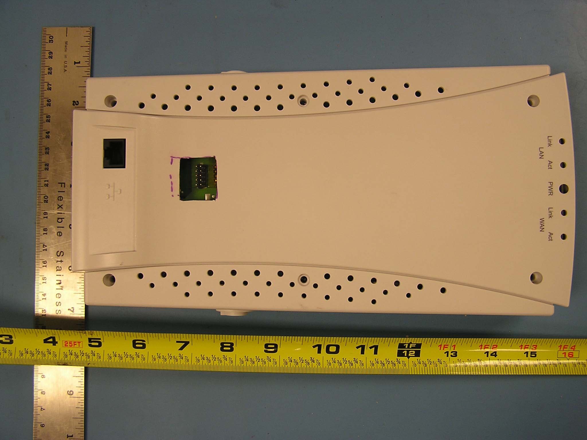
Click to zoom
Application Details
- Equipment Class
- DTS - Digital Transmission System
- Date of Grant
- Aug 23, 2006
- Application Purpose
- Original Equipment
- Date of Application
- Aug 23, 2006
- Equipment Note
- 802.11 Based, Fixed Wireless Node
- Frequency Range
- 5740.00000000 - 5835.00000000
- Company
- Trilliant Networks, Inc.
- Country
- United States
Documents & Files
Document Text
Text extracted from the exhibit documents filed with the FCC. Open a document above to read the original.
Users Manual
SkyPilot SkyConnector Outdoor and Indoor Installation and Hardware Specification Guide The SkyPilot Networkii Contents About This Guide ..........................................................................................................................5 SkyPilot Networks Solution Overview...................................................................................7 SkyGateway....................................................................................................................................................... 8 SkyExtender and SkyExtender DualBand ........................................................................................ 9 SkyConnector................................................................................................................................................... 9 The SkyConnector Outdoor Installation Kit ..................................................................... 11 What the kit provides ................................................................................................................................12 What else you need ...................................................................................................................................12 Installing a SkyConnector Outdoor..................................................................................... 15 Planning your installation.......................................................................................................................15 Cabling the SkyConnector.....................................................................................................................16 Powering on the SkyConnector .........................................................................................................18 Optimizing location ...................................................................................................................................20 Mounting the SkyConnector................................................................................................................21 Connect to a computer or LAN ..........................................................................................................23 Configuring the SkyConnector ...........................................................................................................24 Accessing the Command-Line Interface ........................................................................... 25 FCC Regulatory Information .................................................................................................. 27 FCC Radio Frequency Interference Statement..........................................................................27 FCC Radiation Exposure Limits............................................................................................................28 Specifications.............................................................................................................................. 29 About This Guide This guide explains how to install and set up a SkyPilot™ SkyConnector™ to provide wireless network access to users of a SkyPilot wireless mesh network. It assumes administrator-level knowledge of IP networks and a familiarity with configuring wireless devices. NOTE Where applicable, all information regarding physical characteristics and FCC Regulatory Information pertain to both the SkyConnector Outdoor and SkyConnector Indoor models. SkyPilot SkyConnector Installation 6 1 SkyPilot Networks Solution Overview SkyPilot Networks™ delivers a wireless, end-to-end broadband solution that seamlessly supports high-capacity, high-coverage mesh networks. Designed for managed-access networks and service providers, the SkyPilot network takes broadband wireless the “last mile” with a cost-effective, robust infrastructure solution. Based on a high-performance architecture that deploys intelligent antenna arrays, the SkyPilot network delivers a dynamic broadband solution with significant advantages for business and home users. SkyPilot wireless devices are simple to install and easily fit into any type of wireless environment—metropolitan, business, or home. The auto-discovery and rapid provisioning features of a SkyPilot wireless mesh network greatly reduce deployment and maintenance costs. Support for multiple topologies and high scalability allow attractive options for rapidly expanding a metro Wi-Fi customer base. A SkyPilot network (as illustrated in Figure 1) may include the following physical components: SkyGateway™ (required) SkyExtender™ SkyExtender™ DualBand SkyConnector™ Indoor SkyConnector™ Outdoor SkyPilot SkyConnector Installation 7 Figure 1. SkyPilot wireless mesh network SkyGateway The SkyGateway operates as a base station for a wireless mesh network. It provides an interface between wired infrastructure and a wireless network of subscribers who enjoy secure, high-speed access to the Internet or to wide area networks (WANs). A SkyPilot wireless network requires at least one SkyGateway for normal operation. If necessary, you can add additional SkyGateways to increase network capacity or provide redundancy. The SkyGateway typically resides at a location with easy access to wired infrastructure—usually a POP (point of presence) or data center. SkyPilot SkyConnector Installation 8 For optimal performance, install the SkyGateway on an elevated site such as a cell tower or the top of a tall building. SkyExtender and SkyExtender DualBand SkyExtenders and SkyExtender DualBands provide a cost-effective way to add capacity and balance network loads, by operating as “repeaters” to extend the wireless range of a SkyGateway (see Figure 1). You can add these devices to your network to expand your coverage footprint and provide redundancy through SkyPilot’s mesh networking features. (A SkyExtender can also provide subscribers with a direct connection to the wireless network via its Ethernet port.) In addition, the Sky…
Text truncated - open the document above for the full version.
Users Manual
SkyConnector Indoor Installation Guide E P C : G N I N R A W R E P O R P M I N O I T A L L A T S N I E G A M A D D L U O C R E T U P M O C R U O Y R E W O P R E T U P M O C E P C E P C : G N I N R A W R E P O R P M I N O I T A L L A T S N I E G A M A D D L U O C R E T U P M O C R U O Y R E W O P R E T U P M O C Power on 2 Plug one end of the 25-foot Ethernet cable into the RJ-45 port on the SkyConnector and the other end into the port labeled “CPE” on the power injector. Connect the AC adapter to the power injector, and plug the adapter into an AC outlet. The Power LED lights to indicate the device is powered on. RJ-45 port Ethernet cable Move the SkyConnector to different parts of the building to find the strongest SkyPilot network signal. When the SkyConnector detects a signal, the WAN Act (WAN Activity) LED starts to blink. (The faster the LED blinks, the stronger the signal.) If the WAN Act LED does not start blinking within 30 seconds, try another location. 90 seconds after a signal is located, the WAN Link LED should start blinking, slowly then more rapidly. When the WAN Link LED turn solid, you are connected to the network. PWR LANWAN LinkLinkActAct Remove the adhesive backing from the four foot pads and place them on the underside of the desk stand. Place the SkyConnector in the desk stand and insert the two knobs as shown. Tighten the knobs to secure the device. Attach stand 2 1 Attach one end of the 7-foot Ethernet cable to the port labeled “Computer” on the power injector and the other end into an Ethernet port on your personal computer or other network device, such as a router. When SkyConnector Indoor is properly connected to the computer, the LAN Link LED lights to indicate a successful connection between the devices. Connect computer 4 Your SkyPilot™ SkyConnector™ Indoor kit provides everything you need to set up your SkyConnector and connect to a provider’s wireless mesh network. Contents of the kit • SkyConnector Indoor • Desk stand and mounting knobs • Power injector • AC adapter • Mounting hardware • Two Ethernet cables (25-foot and 7-foot) About the SkyConnector Your SkyConnector is a plug-and- play device that connects you to a SkyPilot wireless network providing wireless access to the Internet. For optimal operation, you need to place the SkyConnector in a loca- tion that has a line of sight to other SkyPilot equipment. 2055 Laurelwood Road Santa Clara, CA 95054-2747 (408) 764-8000 or (866) SKYPILOT www.skypilot.com What‘s next? Review the documentation provided to you by your service provider for instructions on configuring your computer for access to the Internet as well as broadband applications and services. AC adapter power injector mounting knob computer desk stand Locate signal 3 Blinking WAN Act LED indi- cates network signal. PWR LANWAN LinkLinkActAct Solid WAN Act LED indi- cates network connection. PWR LAN WAN Link Link Act Act Solid LAN Link light indicates successful connection with computer. RJ-45 port Network information ISP help desk IP address Netmask DNS (name servers) © 2006 SkyPilot Networks, Inc. All rights reserved. SkyConnector, SkyPilot, SkyPilot Networks, the SkyPilot logo, and other designated trademarks, trade names, logos, and brands are the property of SkyPilot Networks, Inc. or their respective owners. Product specifications are subject to change without notice. This material is provided for informational purposes only; SkyPilot assumes no liability related to its use and expressly disclaims any implied warranties of merchantability or fitness for any particular purpose. FCC Regulatory Information FCC Radio Frequency Interference Statement This equipment has been tested and found to comply with the limits for a Class B digital device, pursuant to Part 15 of the FCC Rules. These limits are designed to provide reasonable protection against harmful interference in a residential installation. This equipment generates, uses and can radiate radio frequency energy and, if not installed and used in accordance with the instructions, may cause harmful interference to radio communications. However, there is no guarantee that interference will not occur in a particular installation. If this equipment does cause harmful interference to radio or television reception, which can be determined by turning the equipment off and on, the user is encouraged to try to correct the interference by one or more of the following measures: o Reorient or relocate the receiving antenna. o Increase the separation between the equipment and receiver. o Connect the equipment into an o which the receiver is connected. utlet on a circuit different from that to Consult the dealer or an experienced radio/TV technician for help. pproval of the manufacturer void the user's authority to perate the equipment. o The user of this product is cautioned that changes or modifications made to the equipment without the a o
Cover Letter(s)
1 Helen Zhao Subject: FW: answer: Skypilot Network Inc., FCC ID: RV7-SC2110, Assessment NO.: AN06T6059, (indoor) Setup Photos(revised).pdf CPE Patch Antenna Specificatio... Theory Of Operation(revised).p. User Manual(revised).pd f 06U10324-6C FCC DTS Report.In... -----Original Message----- From: Claire Hoque Sent: Thursday, August 24, 2006 11:14 AM To: Helen Zhao Subject: answer: Skypilot Network Inc., FCC ID: RV7-SC2110, Assessment NO.: AN06T6059, (indoor) Hi Helen, Pls see answer below, thanks. -----Original Message----- Sent: Wednesday, August 16, 2006 4:45 PM Subject: Skypilot Network Inc., FCC ID: RV7-SC2110, Assessment NO.: AN06T6059, Notice#1 Question #1: The user manual (page 29) indicates "Frequency band: 4.940-5.150, 5.150-5.450, 5.450-5.725, 5.725-5.850GHz." The EUT was tested in 5.725-5.850GHz band only, if the device has the capability to operate in other bands, please perform additional test; Otherwise, please update the user manual. By the way, the same page indicates "Antennas: panel 17dBi", which does not agree with Antenna spec in the filing. Please correct discrepancy. <answer>The correct band for US is 5.725-5.850GHz, and the correct antenna gain is 16.5dBi. Manual and antenna spec. are all revised. Question #2: The schematic diagram shows the EUT has an 802.11g radio, if the device has the capability to operate at 11g mode, please perform additional test, you may need to file as composite device; Otherwise, please update the document. <answer>802.11g function is disabled for this application, pls see revised theory of op. Question #3: The setup photos show power line conducted emission test was done with Outdoor unit which is under a separate filing FCC ID: RV7-SC1110. Please justify why the test data of outdoor unit can be used for this filing. Please also update the test plots to show correct test mode. <answer>report is revised. Question #4: The test was done at low: 5740MHz, middle 5785MHz, high 5835MHz, so the correct operating frequency should be 5740-5835MHz, the test report section 5.2 and form 731 list wrong frequency band, please update. <answer>report/setup photos and 731 form are all revised. 2 Best Regards, Helen Zhao The items indicated above must be submitted before processing can continue on the above referenced application. Failure to provide the requested information within 30 days of the original e-mail date may result in application dismissal and forfeiture of the filing fee. Also, please note that partial responses increase processing time and should not be submitted. Any questions about the content of this correspondence should be directed to the e-mail address listed below the name of the sender.
ID Label/Location Info
PROPOSED FCC ID LABEL AND LOCATION Skypilot Network Inc. This device complies with Part 15 of the FCC Rules. Operation is subject to the following two conditions: (1) this device may not cause harmful interference, and (2) this device must accept any interference received, including interference that may cause undesired operation. FCC ID: RV7-SC2110
Parts List/Tune Up Info
CPE Patch Antenna Specifications 500-00241-01 Electrical Parameter Spec Gain 16.5 dBi Beam Width Azimuth 30 deg Elevation 9 deg Mechanical Parameter Spec Dimensions 10.0” (L) x 4.5” (W) x 0.005” (T)
Test Report
FCC CFR47 PART 15 SUBPART C CERTIFICATION TEST REPORT FOR 802.11 BASED, FIXED WIRELESS NODE MODEL NUMBER: SkyConnector INDOOR SC2110 FCC ID: RV7-SC2110 REPORT NUMBER: 06U10324-6, REVISION C ISSUE DATE: AUGUST 18, 2006 Prepared for SKYPILOT NETWORKS INC. 2055 LAURELWOOD ROAD 2 nd FLOOR SANTA CLARA, CA 95054-2747 Prepared by COMPLIANCE CERTIFICATION SERVICES 561F MONTEREY ROAD MORGAN HILL, CA 95037, USA TEL: (408) 463-0885 FAX: (408) 463-0888 REPORT NO: 06U10324-6C DATE: AUGUST 18, 2006 EUT: 802.11 BASED, FIXED WIRELESS NODE FCC ID: RV7-SC2110 Page 2 of 54 COMPLIANCE CERTIFICATION SERVICES DOCUMENT NO: CCSUP4031A 561F MONTEREY ROAD, MORGAN HILL, CA 95037 USA TEL: (408) 463-0885 FAX: (408) 463-0888 This report shall not be reproduced except in full, without the written approval of CCS. Revision History Rev. Issue Date Revisions Revised By -- 7/28/06 Initial Issue based on CCS Report 06U10324-1 A. Ilarina B 8/15/06 Update antenna gain, add MPE section A. Ilarina C 8/18/2006 Update Setup Photos, update output power table under section 5.2 A. Ilarina REPORT NO: 06U10324-6C DATE: AUGUST 18, 2006 EUT: 802.11 BASED, FIXED WIRELESS NODE FCC ID: RV7-SC2110 Page 3 of 54 COMPLIANCE CERTIFICATION SERVICES DOCUMENT NO: CCSUP4031A 561F MONTEREY ROAD, MORGAN HILL, CA 95037 USA TEL: (408) 463-0885 FAX: (408) 463-0888 This report shall not be reproduced except in full, without the written approval of CCS. TABLE OF CONTENTS 1. ATTESTATION OF TEST RESULTS............................................................................................. 4 2. TEST METHODOLOGY .................................................................................................................. 5 3. FACILITIES AND ACCREDITATION .......................................................................................... 5 4. CALIBRATION AND UNCERTAINTY.......................................................................................... 5 4.1. MEASURING INSTRUMENT CALIBRATION ............................................................................. 5 4.2. MEASUREMENT UNCERTAINTY ............................................................................................... 5 5. EQUIPMENT UNDER TEST............................................................................................................6 5.1. DESCRIPTION OF EUT ..............................................................................................................6 5.2. MAXIMUM OUTPUT POWER .................................................................................................... 6 5.3. DESCRIPTION OF AVAILABLE ANTENNAS ............................................................................. 6 5.4. SOFTWARE AND FIRMWARE .................................................................................................... 6 5.5. WORST-CASE CONFIGURATION AND MODE......................................................................... 7 5.6. DESCRIPTION OF TEST SETUP ................................................................................................ 7 6. TEST AND MEASUREMENT EQUIPMENT ................................................................................ 9 7. LIMITS AND RESULTS ................................................................................................................. 10 7.1. CHANNEL TESTS FOR THE 5725 TO 5850 MHz BAND ......................................................... 10 7.1.1. 6 dB BANDWIDTH ........................................................................................................... 10 7.1.2. 99% BANDWIDTH............................................................................................................ 14 7.1.3. PEAK OUTPUT POWER .................................................................................................. 18 7.1.4. MAXIMUM PERMISSIBLE EXPOSURE ........................................................................ 23 7.1.5. AVERAGE POWER........................................................................................................... 26 7.1.6. PEAK POWER SPECTRAL DENSITY ............................................................................ 27 7.1.7. CONDUCTED SPURIOUS EMISSIONS.......................................................................... 31 7.2. RADIATED EMISSIONS.............................................................................................................38 7.2.1. TRANSMITTER RADIATED SPURIOUS EMISSIONS ................................................. 38 7.2.2. TRANSMITTER ABOVE 1 GHz FOR 5725 TO 5850 MHz BAND ................................ 41 7.2.3. WORST-CASE RADIATED EMISSIONS BELOW 1 GHz ............................................. 42 7.3. POWERLINE CONDUCTED EMISSIONS ................................................................................ 46 8. SETUP PHOTOS .............................................................................................................................. 50 REPORT NO: 06U10324-6C DATE: AUGUST 18, 2006 EUT: 802.11 BASED, FIXED WIRELESS NODE FCC ID: RV7-SC2110 Page 4 of 54 COMPLIANCE CERTIFICATION SERVICES DOCUMENT NO: CCSUP4031A 561F MONTEREY ROAD, MORGAN HILL, CA 95037 USA TEL: (408) 463-0885 FAX: (408) 463-0888 This report shall not be reproduced except in full, without the written approval of CCS. 1. ATTESTATION OF TEST RESULTS COMPANY NAME: SKYPILOT NETWORKS INC. 2055 LAURELWOOD ROAD 2 nd FLOOR SANTA CLARA, CA 95054-2747 EUT DESCRIPTION: 802.11BASED, FIXED WIRELESS NODE MODEL: SkyConnector Indoor SC2110 SERIAL NUMBER: None DATE TESTED: JUNE 06 - 13, 2006 APPLICABLE STANDARDS STANDARD TEST RESULTS FCC PART 15 SUBPART C NO NON-COMPLIANCE NOTED Compliance Certification Services, Inc. tested the above equipment in accordance with the requirements set forth in the above standards. The test results show that the equipment tested is capable of demonstrating compliance with the requirements as documented in this report. Note: The results documented…
Text truncated - open the document above for the full version.
Test Setup Photos
REPORT NO: 06U10324-6C DATE: AUGUST 18, 2006 EUT: 802.11 BASED, FIXED WIRELESS NODE FCC ID: RV7-SC2110 Page 50 of 54 COMPLIANCE CERTIFICATION SERVICES DOCUMENT NO: CCSUP4031A 561F MONTEREY ROAD, MORGAN HILL, CA 95037 USA TEL: (408) 463-0885 FAX: (408) 463-0888 This report shall not be reproduced except in full, without the written approval of CCS. 8. SETUP PHOTOS ANTENNA PORT CONDUCTED RF MEASUREMENT SETUP ANTENNA PORT CONDUCTED PHOTO REPORT NO: 06U10324-6C DATE: AUGUST 18, 2006 EUT: 802.11 BASED, FIXED WIRELESS NODE FCC ID: RV7-SC2110 Page 51 of 54 COMPLIANCE CERTIFICATION SERVICES DOCUMENT NO: CCSUP4031A 561F MONTEREY ROAD, MORGAN HILL, CA 95037 USA TEL: (408) 463-0885 FAX: (408) 463-0888 This report shall not be reproduced except in full, without the written approval of CCS. RADIATED RF MEASUREMENT SETUP INDOOR UNIT RADIATED FRONT PHOTO REPORT NO: 06U10324-6C DATE: AUGUST 18, 2006 EUT: 802.11 BASED, FIXED WIRELESS NODE FCC ID: RV7-SC2110 Page 52 of 54 COMPLIANCE CERTIFICATION SERVICES DOCUMENT NO: CCSUP4031A 561F MONTEREY ROAD, MORGAN HILL, CA 95037 USA TEL: (408) 463-0885 FAX: (408) 463-0888 This report shall not be reproduced except in full, without the written approval of CCS. RADIATED BACK PHOTO REPORT NO: 06U10324-6C DATE: AUGUST 18, 2006 EUT: 802.11 BASED, FIXED WIRELESS NODE FCC ID: RV7-SC2110 Page 53 of 54 COMPLIANCE CERTIFICATION SERVICES DOCUMENT NO: CCSUP4031A 561F MONTEREY ROAD, MORGAN HILL, CA 95037 USA TEL: (408) 463-0885 FAX: (408) 463-0888 This report shall not be reproduced except in full, without the written approval of CCS. POWERLINE CONDUCTED EMISSIONS MEASUREMENT SETUP LINE CONDUCTED FRONT PHOTO REPORT NO: 06U10324-6C DATE: AUGUST 18, 2006 EUT: 802.11 BASED, FIXED WIRELESS NODE FCC ID: RV7-SC2110 Page 54 of 54 COMPLIANCE CERTIFICATION SERVICES DOCUMENT NO: CCSUP4031A 561F MONTEREY ROAD, MORGAN HILL, CA 95037 USA TEL: (408) 463-0885 FAX: (408) 463-0888 This report shall not be reproduced except in full, without the written approval of CCS. END OF REPORT LINE CONDUCTED BACK PHOTO
Contact Information
Applicant
Daniel Tousignant(Certification & Compliance Eng.)
Test Firm
Compliance Certification ServicesBarbara Judge
Technical Specifications
| # | Rule Parts | Frequency Range | Power Output |
|---|---|---|---|
| 1 | 15C | 5.74 GHz - 5.83 GHz | 349.10 mW |
Other Applications from Trilliant Networks, Inc.

RV7-5G1100
Jun 07, 2012Wireless Mesh WAN Backhaul Node
Equipment Class
DTS - Digital Transmission System
RV7-CONN
May 17, 2012Wireless Mesh Wide Area Network CPE
Equipment Class
NII - Unlicensed National Information Infrastructure TX
RV7-SC6000
Jan 27, 2011Dual Radio Concurrent AP/CB
Equipment Class
NII - Unlicensed National Information Infrastructure TX
RV7-SC6010
Jul 06, 2010Dual Radio Concurrent AP/CB
Equipment Class
DTS - Digital Transmission System
RV7-SC4120
Apr 13, 2008DUAL BAND 802.11 a/b/g BASED, FIXED WIRELESS NODE
Equipment Class
DTS - Digital Transmission System