RWU-MWM01802.15.4 Transceiver
Newell Rubbermaid Inc.
Click to zoom
Application Details
- Equipment Class
- DTS - Digital Transmission System
- Date of Grant
- Feb 02, 2010
- Application Purpose
- Original Equipment
- Date of Application
- Feb 02, 2010
- Equipment Note
- 802.15.4 Transceiver
- Frequency Range
- 2405.00000000 - 2480.00000000
- Company
- Newell Rubbermaid Inc.
- Country
- United States
Documents & Files
Document Text
Text extracted from the exhibit documents filed with the FCC. Open a document above to read the original.
Users Manual
Federal Communication Commission Interference Statement This equipment has been tested and found to comply with the limits for a Class B digital device, pursuant to Part 15 of the FCC Rules. These limits are designed to provide reasonable protection against harmful interference in a residential installation. This equipment generates uses and can radiate radio frequency energy and, if not installed and used in accordance with the instructions, may cause harmful interference to radio communications. However, there is no guarantee that interference will not occur in a particular installation. If this equipment does cause harmful interference to radio or television reception, which can be determined by turning the equipment off and on, the user is encouraged to try to correct the interference by one of the following measures: - Reorient or relocate the receiving antenna. - Increase the separation between the equipment and receiver. - Connect the equipment into an outlet on a circuit different from that to which the receiver is connected. - Consult the dealer or an experienced radio/TV technician for help. This device complies with Part 15 of the FCC Rules. Operation is subject to the following two conditions: (1) This device may not cause harmful interference, and (2) this device must accept any interference received, including interference that may cause undesired operation. FCC Caution : Any changes or modifications not expressly approved by the party responsible for compliance could void the user's authority to operate this equipment. INDUSTRY CANADA STATEMENTS Operation is subject to the following two conditions: (1) this device may not cause interference, and (2) this device must accept any interference, including interference that may cause undesired operation of the device. To reduce potential radio interference to other users, the antenna type and its gain should be so chosen that the equivalent isotropically radiated power (e.i.r.p.) is not more than that permitted for successful communication. This device has been designed to operate with the antennas listed below , and having a maximum gain of 0 dB. Antennas not included in this list or having a gain greater than 0 dB are strictly prohibited for use with this device. The required antenna impedance is 50 ohms. Approved antenna: On-Board PCB trace antenna Newell Rubbermaid Inc. responsibilities to comply with FCC and Industry Canada Regulations The mimio Wireless Module has been certified for integration into products only by Newell Rubbermaid Inc. integrators under the following conditions: This module complies with FCC and Industry Canada RF radiation exposure limits set forth for general population/uncontrolled environment. To maintain compliance, this module must not be co-located or operating in conjunction with any other antenna or transmitter. As long as the above condition is met, further transmitter testing will not be required. However, the Newell Rubbermaid integrator is still responsible for testing their end- product for any additional compliance requirements required with this module installed (for example, digital device emissions, PC peripheral requirements, etc.). IMPORTANT NOTE: In the event that these conditions can not be met (for certain configurations or co-location with another transmitter), then the FCC and Industry Canada authorizations are no longer considered valid and the FCC ID and IC Certification Number can not be used on the final product. In these circumstances, the Newell Rubbermaid Inc. integrator will be responsible for re-evaluating the end product (including the transmitter) and obtaining a separate FCC and Industry Canada authorization. End Product Labeling The mimio Wireless Module is labeled with its own FCC ID and IC Certification Number. If the FCC ID and IC Certification Number are not visible when the module is installed inside another device, then the outside of the device into which the module is installed must also display a label referring to the enclosed module. In that case, the final end product must be labeled in a visible area with the following: “Contains FCC ID: RWU-MWM01” “Contains IC: 4952A-MWM01” The Newell Rubbermaid Inc. mimio Wireless Module must only use the approved antenna(s) listed above, which have been certified with this module. The Newell Rubbermaid Inc. integrator has to be aware not to provide information to the end user regarding how to install or remove this RF module or change RF related parameters in the user manual of the end product. The user manual for the end product must include the following information in a prominent location: This device complies with FCC and Industry Canada RF radiation exposure limits set forth for general population/uncontrolled environment. To maintain compliance, this device must not be co-located or operating in conjunction with any other antenna or transmitter.
Cover Letter(s)
3 Glenlake Parkway | Atlanta, GA 30328 | Phone +1 (770) 418-7000 | www.newellrubbermaid.com Wednesday, August 05, 2009 To: Federal Communications Commission 7435 Oakland Mills Road Columbia, MD 21046-1609 Bureau Veritas Consumer Product Services Littleton Distribution Center One Distribution Center Circle #1 Littleton, MA 01460, USA Re: Confidentiality Request Gentlemen: This letter is to comply with 47 CFR 0.457(d)(2) pertaining to confidential material. Newell Rubbermaid Inc. requests that the following documents regarding this submission for FCC ID RWU-MWM01 be kept confidential: 1. Schematics 2. Block Diagram 3. Circuit/Technical Description The material above contains technical data, which would customarily be guarded from competitors. Sincerely, Chad Lewis OEM Engineer, R&D mimio - A Newell Rubbermaid Company One Charles Park, 3rd Floor Cambridge, MA 02142-1254 Direct (617) 902.2097 [email protected] Wednesday, August 05, 2009
Cover Letter(s)
3 Glenlake Parkway | Atlanta, GA 30328 | Phone +1 (770) 418-7000 | www.newellrubbermaid.com Agent’s Authorization Letter Wednesday, August 05, 2009 I, the grantee contact of record at mimio – A Newell Rubbermaid Company, do hereby authorize, until further notice, Mairaj Hussain of Bureau Veritas Consumer Product Services, Littleton Distribution Center, One Distribution Center Circle #1, Littleton, MA 01460, USA, to act on our behalf in dealings before the Federal Communications Commission with respect to all matters relating to equipment authorizations under 47 CFR. This authorization includes, but is not limited to, the signing of Form 731. I certify that no party (as defined in 47 CFR 1.2002) to this application, including myself, is subject to a denial of federal benefits, that include FCC benefits, pursuant to section 5301 of the Anti-Drug Abuse Act of 1988, 21 U.S.C., 853A. Certified By: Chad Lewis OEM Engineer, R&D mimio - A Newell Rubbermaid Company One Charles Park, 3rd Floor Cambridge, MA 02142-1254 Wednesday, August 05, 2009
Cover Letter(s)
3 Glenlake Parkway | Atlanta, GA 30328 | Phone +1 (770) 418-7000 | www.newellrubbermaid.com To Whom It May Concern: This letter is Requesting Limited Single Modular Approval for the mimio Wireless Module RWU-MWM01 This module is to be installed only in Newell Rubbermaid, Inc. end-products and will not be marketed to any other party". Mimio Modular Transmitter Answers FCC ID: RWU-MWM01 Section 15.212 i. The radio elements of the modular transmitter must have their own shielding. The physical crystal and tuning capacitors may be located external to the shielded radio elements. This module does not have a shielding can on the radio elements. ii. The modular transmitter must have buffered modulation/data inputs (if such inputs are provided) to ensure that the module will comply with Part 15 requirements under conditions of excessive data rates or over-modulation. All I/O to the module are buffered from the radio. There is no direct way an input (or output) pin can modulate the radio or change its output. The only data connection to the radio module is a SPI bus. See the block diagram for more detail. iii. The modular transmitter must have its own power supply regulation. The radio transceiver has an integrated voltage regulator for all RF circuitry. iv. The modular transmitter must comply with the antenna and transmission system requirements of Sections 15.203, 15.204(b) and 15.204(c). The antenna must either be permanently attached or employ a “unique” antenna coupler (at all connections between the module and the antenna, including the cable). The “professional installation” provision of Section 15.203 is not applicable to modules but can apply to limited modular approvals under paragraph (b) of this section. The radio module utilizes an integrated PCB antenna. No provision for any other antenna connection is provided. v. The modular transmitter must be tested in a stand-alone configuration, i.e., the module must not be inside another device during testing for compliance with Part 15 requirements. Unless the transmitter module will be battery powered, it must comply with the AC line conducted requirements found in Section 15.207. AC or DC power lines and data input/output lines connected to the module must not contain ferrites, unless they will be marketed with the 3 Glenlake Parkway | Atlanta, GA 30328 | Phone +1 (770) 418-7000 | www.newellrubbermaid.com module (see Section 15.27(a)). The length of these lines shall be the length typical of actual use or, if that length is unknown, at least 10 centimeters to insure that there is no coupling between the case of the module and supporting equipment. Any accessories, peripherals, or support equipment connected to the module during testing shall be unmodified and commercially available (see Section 15.31(i)). The module may be powered by both a battery and/or an external power supply. The module will be powered with an AC/DC power supply for AC conducted measurements. The module was tested in a stand-alone configuration. vi. The modular transmitter must be equipped with either a permanently affixed label or must be capable of electronically displaying its FCC identification number. The module will have a label permanently attached, and the FCC declaration appears in the product manual. Refer to the product manual for product labeling instructions. vii. The modular transmitter must comply with any specific rules or operating requirements that ordinarily apply to a complete transmitter and the manufacturer must provide adequate instructions along with the module to explain any such requirements. A copy of these instructions must be included in the application for equipment authorization. An instruction manual is included with the application for authorization. The module meets all applicable 15.247 requirements. viii. The modular transmitter must comply with any applicable RF exposure requirements in its final configuration. This module complies with FCC RF exposure requirements for general population to be installed in portable end products. Details can be seen in the RF exposure exhibit. Sincerely, Chad Lewis OEM Engineer, R&D mimio - A Newell Rubbermaid Company One Charles Park, 3rd Floor Cambridge, MA 02142-1254 Direct (617) 902.2097 [email protected]
ID Label/Location Info
3 Glenlake Parkway | Atlanta, GA 30328 | Phone +1 (770) 418-7000 | www.newellrubbermaid.com A drawing that shows the location of the label on the mimio Wireless Module RWU- MWM01
RF Exposure Info
This module will be installed in grantee’s end products that are in portable RF exposure category. Frequency Range: 2405-2480MHz Low threshold = 60/f(GHz) mW = 60 / 2.480 = 24.19mW Conducted Output Power Measured (dBm) = 4.3dBm Antenna Gain (dBi) = 0dBi EIRP = 2.7mW Conducted Output Power (mW) = 2.7mW Since both Conducted output power and EIRP are below the low threshold, device complies with FCC’s RF radiation exposure limits for general population/uncontrolled exposure category for a portable device without SAR evaluation.
Test Report
Curtis-Straus LLC is accredited to ISO/IEC 17025 by A2LA for the specific scope of accreditation under Certificate Number 1627-01. This report may contain data which is not covered by the A2LA accreditation. Any opinions or interpretations expressed in this report are outside the scope of our A2LA accreditation as A2LA only accredits testing. ____________________________________________________________ Curtis-Straus • •• • 527 Great Road • •• • Littleton, MA • •• • TEL (978) 486-8880 • •• • FAX (978) 486-8828 page 1 of 27 Test Report Report No EJ1067 Client mimio One Charles Park, 3 rd Floor Cambridge, MA 02142-1254 Phone 617-902-2097 FRN 0010489151 Model MWM01 FCC ID IC RWU-MWM01 4592A-MWM01 Equipment Type Equipment Code Digital Transmission System DTS Results As detailed within this report Prepared by Evan Gould – Compliance Engineer Authorized by Mairaj Hussain – EMC Supervisor Issue Date 9/25/09 Conditions of Issue This Test Report is issued subject to the conditions stated in the ‘Conditions of Testing’ section on page 26 of this report. Test Report for mimio • •• • Report No. EJ1067-1 September 25, 2009 ______________________________________________________________________ ____________________________________________________________ Curtis-Straus • •• • 527 Great Road • •• • Littleton, MA • •• • TEL (978) 486-8880 • •• • FAX (978) 486-8828 page 2 of 27 Contents Summary.................................................................................................................................3 Test Methodology ....................................................................................................................3 Product Tested - Configuration Documentation .......................................................................4 Emission Bandwidth / 99% Occupied Bandwidth .....................................................................5 Peak Output Power .................................................................................................................7 Power Spectral Density .........................................................................................................10 Out-of-band Emissions ..........................................................................................................12 Restricted Band Radiated Spurious Emissions......................................................................14 Line Conducted Emissions ....................................................................................................15 Receiver Spurious Emissions ................................................................................................16 Conditions Of Testing ............................................................................................................26 Test Report for mimio • •• • Report No. EJ1067-1 September 25, 2009 ______________________________________________________________________ _____________________________________________________________ Curtis-Straus • •• • 527 Great Road • •• • Littleton, MA • •• • TEL (978) 486-8880 • •• • FAX (978) 486-8828 page 3 of 27 Summary This test report supports an application for certification (modular approval) of a transmitter operating pursuant to 47 CFR 15.247. The product is the mimio Wireless Module. It is a digitally modulated transmitter operating in the range 2405-2480MHz. Test Methodology Testing was performed according to ANSI C63.4-2003. Radiated emissions were maximized by rotating the device around its three orthogonal axes, as well as varying the test antenna’s height and polarity. Since this is a module which could be integrated into a product powered from the AC public utility lines, AC line conducted emissions were measured on the AC side of the DC supply. AC line conducted emissions was performed with a 50Ω / 50μH LISN. Test Report for mimio • •• • Report No. EJ1067-1 September 25, 2009 ______________________________________________________________________ _____________________________________________________________ Curtis-Straus • •• • 527 Great Road • •• • Littleton, MA • •• • TEL (978) 486-8880 • •• • FAX (978) 486-8828 page 4 of 27 Product Tested - Configuration Documentation EUT Configuration Work Order: J1067 Company: mimio Company Address: One Charles Park, 3rd Floor Cambridge, MA 02142-1254 Contact: Chad Lewis Person Present: Josh Schadel MNSN EUT: MWM011 EUT Description: Mimio Wireless Module EUT Max Frequency:2480MHz Support Equipment: MNSN Atmel evaluation boardSTK60020080227 EUT Ports: Port LabelPort Type No. of ports No. PopulatedCable TypeShieldedFerritesLength Max Length In/Out NEBS TypeUnpopulated Reason None Software / Operating Mode Description: Using Hyperterminal on support PC to set channel and power level. Test Report for mimio • •• • Report No. EJ1067-1 September 25, 2009 ______________________________________________________________________ _____________________________________________________________ Curtis-Straus • •• • 527 Great Road • •• • Littleton, MA • •• • TEL (978) 486-8880 • •• • FAX (978) 486-8828 page 5 of 27 Emission Bandwidth / 99% Occupied Bandwidth LIMIT “The minimum 6dB bandwidth shall be at least 500kHz.” [15.247(a)(2)] EQUIPMENT BROWN SPECTRUM ANALYZER MEASUREMENTS Channel Frequency 6dB Emission Bandwidth (MHz) (MHz) 11 2405 1.4 18 2440 1.45 26 2480 1.5 Testing performed by Evan Gould on 8/5/09. PLOTS Ch.11 – Emission Bandwidth Test Report for mimio • •• • Report No. EJ1067-1 September 25, 2009 ______________________________________________________________________ _____________________________________________________________ Curtis-Straus • •• • 527 Great Road • •• • Littleton, MA • •• • TEL (978) 486-8880 • •• • FAX (978) 486-8828 page 6 of 27 Ch.18 – Emission Bandwidth Ch.25 – Emission Bandwidth Test Report for mimio • •• • Report No. EJ1067-1 September 25, 2009 ______________________________________________________________________ ___________________________________________________________…
Text truncated - open the document above for the full version.
Contact Information
Applicant
Chad Lewis
Test Firm
BUREAU VERITAS CONSUMER PRODUCTS SERVICES, INC.Ozgur Ozturk
[email protected]978-486-8880
Technical Specifications
| # | Rule Parts | Frequency Range | Power Output |
|---|---|---|---|
| 1 | 15C | 2.40 GHz - 2.48 GHz | 2.70 mW |
Other Applications from Newell Rubbermaid Inc.
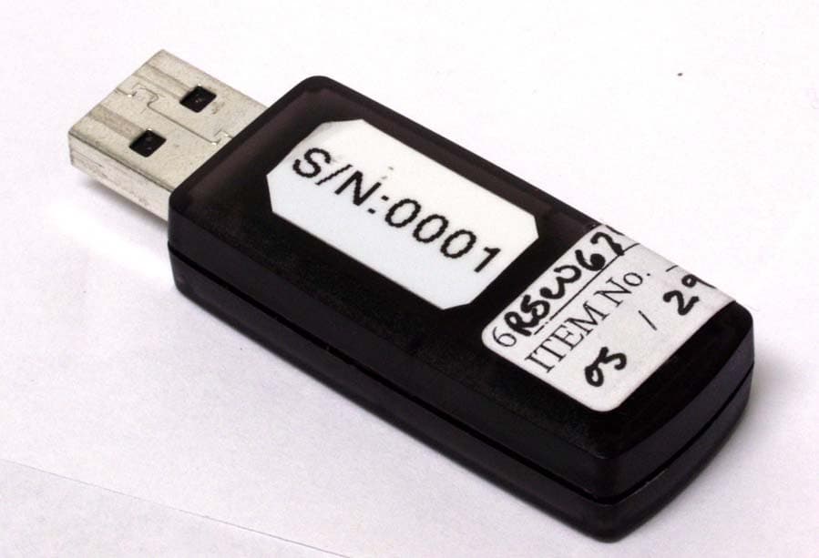
RWU-DMA0203
Oct 04, 2007USB Adapter
Equipment Class
DTS - Digital Transmission System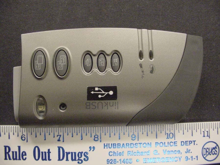
RWU-DMA0202M
Apr 06, 2004Mimio Xi Whiteboard Capture System
Equipment Class
DXX - Part 15 Low Power Communication Device Transmitter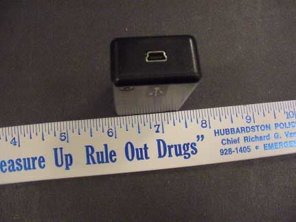
RWU-DMA0202
Apr 06, 2004Mimio Xi Whireboard Capture System
Equipment Class
DXX - Part 15 Low Power Communication Device Transmitter