RWVPANTERAMobile Phone
Sumtech Industry Development Co., Ltd.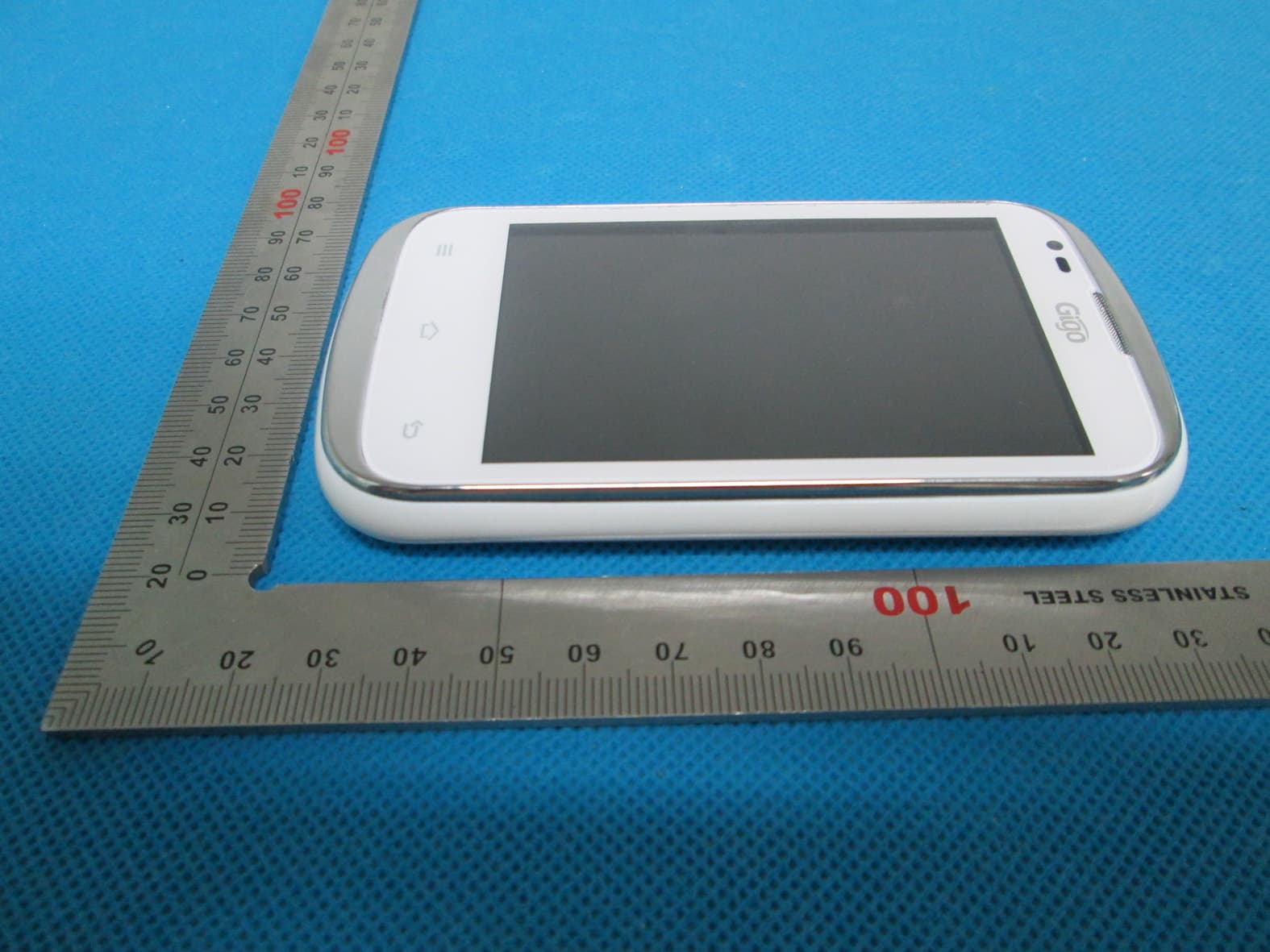
Click to zoom
Application Details
- Equipment Class
- PCE - PCS Licensed Transmitter held to ear
- Date of Grant
- Jul 17, 2013
- Application Purpose
- Original Equipment
- Date of Application
- Jul 17, 2013
- Equipment Note
- Mobile Phone
- Frequency Range
- 1850.20000000 - 1909.80000000
- Country
- China
Documents & Files
Document Text
Text extracted from the exhibit documents filed with the FCC. Open a document above to read the original.
Users Manual
GSM Mobile Phone Brand Name: GIGO,SUM, MAMBA MOBILE Model Name: PANTERA FCC ID: RWVPANTERA 2 I. Safety Precautions Before using a mobile phone, please read and observe the following rules. While driving or answering a call, please use an earphone or stop your car. Mobile phone interferes with aircraft communication, please ensure that mobile phone power off during the entire flight. All mobile phones may be disturbed, and affect their performance. Please don’t use mobile phone and turn off your phone where medical equipments exist. To ensure the best performance or avoid damage to mobile phone, please use the original accessories and batteries. At the gas station and close to the fuel and chemicals and other dangerous goods, please power off your mobile phone to avoid explosion. To avoid interference of the blasting operation, In the scene of the explosion or post "Turn off the radio" icon in the local, please power off your mobile phone. Please don't burn batteries as ordinary garbage, to avoid the risk of life and damage to the environments. Please abide by the local environmental policy, timely deal with or recycle the waste batteries. Before your mobile phone is connect with another equipment, please read carefully this manual to ensure safety. Some small articles (such as T-Flash card, etc.) should be placed out of children reach, to prevent children swallowing or other hazard. Please backup the important information or keep a written record, to prevent its loss. When sending an emergency call, please ensure your mobile phone power on and in a service area, inform your position, without permission, please don't end this call. 3 II. Before Use 1. Install and Unload SIM Card 1.1 About SIM Card Before using the phone, you must insert valid SIM (Subscriber Identity Module) card in the phone. SIM card provided by network supplier. All the information related to network connection are recorded in the chip of SIM card, also the names, telephone numbers and SMS that storing in the name card holder of SIM card. You can take out SIM card from your phone, and use it in any GSM mobile phone (new mobile phone can read SIM card automatically). In order to avoid losing or damaging the information saves in SIM card, please don’t touch the metal contact surface, and place SIM card in the place that away from electricity and magnetic force. Once SIM card is damaged, you can’t use the phone normally. Prompt: Please make sure to power off the phone before taking out SIM card. It is absolutely forbidden to insert or take out SIM card with external power supply; otherwise it may damage SIM card and the phone. 1.2 Insert and Unload SIM Card Metal contact surface of SIM card is easily scratched. You must take out SIM card carefully before the assembly. Power off the phone, remove the rear cover, battery or other external power supply. Make the end of SIM card without cutting angle inside and aim at the card slot of the phone and metal surface of SIM card face downward, then insert SIM card to the card slot of the phone, the other SIM card is also inserted in this way. When taking out SIM card, directly pull it outward and then can take out SIM card. Prompt: Without special explanation inserting two SIM cards are defaulted in the manual. If you just insert one SIM card, maybe some options of the menu will not be shown. 2. T-Flash Card Aim at the T card slot and push the T card gently, and the card will be inserted correctly. Prompt: If the memory card is failed, please check whether it is correctly placed and good contact of metal point. 3. Install and Unload Battery Take off the rear cover of the mobile. Make one end of battery with metal surface aim at the battery connector. Then gently press the battery downward using the finger, and then press the other end to install the battery. Prompt: Please operate correctly to avoid damaging the battery connector. 4. Charging 4.1 Charger Insert the charger on the charging interface at the top of the phone. After inserting the charging plug, battery strength icon stripe at the top right corner of the screen is scrolling, which means that the 4 charging is processing; when the stripe is full of the whole icon and stop scrolling, which means that the battery charging is completed; when the charging is completed, please pull out the plug. When electric quantity is not enough, warning message will be sent; and electric quantity shows empty. When electric quantity is too low, the phone will power off automatically. Please don’t make the battery in the status of not enough electric quantity for a long time; otherwise it may damage the battery quality and service life. Please don’t charge the battery for a long time. Prompt: In order to ensure normal operation of the phone, please make sure to use the designated charger. 4.2 USB disk Identification After USB disk is inserted, you can deal with data in USB disk after its light is on. Please refer to “File Manager” for the usage of USB Disk. Prompt: It is forbidden to remove USB disk when data in USB disk is being copied, transferred or deleted to prevent data damage. 4.3 Transferring Data With Computer 4.3.1 Install USB Connect mobile phone to a computer with a USB cable, drag out the notification bar. Touch “USB Connected”, choose and click “USB storage”, then on the computer, you can view data in Device and SD Card storage. So data transferring can be performed between this device and the computer. 4.3.2 Disconnect USB After data is mounted onto the computer, you can drag out the notification bar, touch to turn Off “USB Storage”, and then disconnect with USB link. Prompt: It is forbidden to disconnect USB link during transferring data, because it can lead to data loss or damage. IV. Quick User Guide The phone has not only the basic functions of mobile phone, but also support rich, practical and rapid feature functions, can be briefly introduced as follows: 1. Power On/Off In the power-off mode, long press [Power] key, it…
Text truncated - open the document above for the full version.
Cover Letter(s)
July 03, 2013 Federal Communication Commission Authorization and Evaluation Division FCC ID: RWVPANTERA Re: Confidentiality Request Pursuant to Sections 0.457 and 0.459 of the Commission’s Rules, the applicant hereby requests confidential treatment of information applied this application as outlined below: 1: Block Diagram 2: Circuit Diagram 3: Operational Description 4: Parts List 5: Tune Up Procedure The above materials contain trade secrets and proprietary information not customarily released to the public. The public disclosure of these matters might be harmful to the applicant and provide unjustified benefits to its competitors. The Applicant understands that pursuant to Rules 0.457, disclosure of this Application and all accompanying documentation will not be made before the date of the Grant for this application. Sincerely, Sumtech Industry Development Co., Ltd. Contact person: IVY QIU Title: Manager Tel: 86-755-25199083
External Photos
External Photos TOTAL VIEW OF EUT TOP VIEW OF EUT BOTTOM VIEW OF EUT FRONT VIEW OF EUT BACK VIEW OF EUT LEFT VIEW OF EUT RIGHT VIEW OF EUT
ID Label/Location Info
FCC ID Label Location GSM Mobile Phone Model: PANTERA Trade Name: GIGO FCC ID: RWVPANTERA 6810,S6810, N6810,F9 SUM, MAMBA MOBILE
ID Label/Location Info
Sumtech Industry Development Co., Ltd Room521, Sanjiu Hotel, No.1001 East Shennian Road, luohu, Shenzhen, China Date: Jul. 03, 2013 Statement We, Sumtech Industrial Development Co., Ltd states that our device, FCC ID: RWVPANTERA, has no space to put the label except the battery compartment of this device. It is visible to the users as they purchase the products and install the battery. Regards Company: Sumtech Industry Development Co., Ltd Contact Person: IVY QIU Title: Manager
Internal Photos
Internal Photos OPEN VIEW OF EUT-1 GSM Antenna WIFI Antenna OPEN VIEW OF EUT-2 OPEN VIEW OF EUT-3 INTERNAL VIEW OF EUT-1 INTERNAL VIEW OF EUT-2 BT Antenna
RF Exposure Info
Report No.: AGC00417130602FH01 Page 1 of 133 SAR Test Report Report No.: AGC00417130602FH01 FCC ID : RWVPANTERA PRODUCT DESIGNATION : GSM Mobile Phone APPLICATION PURPOSE : Original Equipment BRAND NAME : GIGO, SUM, MAMBA, MOBILE MODEL NAME : PANTERA, 6810, S6810, N6810, F9 CLIENT : Sumtech Industry Development Co., Ltd. DATE OF ISSUE : Jul.01, 2013 STANDARD(S) : FCC Oet65 Supplement C June 2001 IEEE Std. 1528-2003 47CFR § 2.1093 REPORT VERSION : V1.0 Attestation of Global Compliance(Shenzhen) Co., Ltd. CAUTION: This report shall not be reproduced except in full without the written permission of the test laboratory and shall not be quoted out of context. Report No.: AGC00417130602FH01 Page 2 of 133 Report Revise Record Report Version Revise Time Issued Date Valid Version Notes V1.0 / Jul.01, 2013 Valid Original Report Report No.: AGC00417130602FH01 Page 3 of 133 Test Report Certification Applicant Name Sumtech Industry Development Co., Ltd. Applicant Address Room521, Sanjiu Hotel, No.1001 East Shennian Road, Luohu, Shenzhen, China Manufacturer Name Sumtech Industry Development Co., Ltd. Manufacturer Address Room521, Sanjiu Hotel, No.1001 East Shennian Road, Luohu, Shenzhen, China Product Designation GSM Mobile Phone Brand Name GIGO, SUM, MAMBA, MOBILE Model Name PANTERA, 6810, S6810, N6810, F9 Different Description All the models are the same, only different in model names. The test model is PANTERA. EUT Voltage DC3.7V by battery Applicable Standard FCC Oet65 Supplement C June 2001 IEEE Std. 1528-2003 47CFR § 2.1093 Test Date Jun.28, 2013 Test Results MAX SAR MEASUREMENT(1g) Head: 0.567 W/Kg Body: 1.046 W/Kg (Maximum Scaling SAR =1.136 W/Kg) simultaneous transmission: 1.437 W/Kg Performed Location Attestation of Global Compliance(Shenzhen) Co., Ltd. 2 F, Building 2, No.1-No.4, Chaxi Sanwei Technical Industrial Park, Gushu, Xixiang Street, Bao'an District, Shenzhen, China Report Template AGCRT-US-2.5G2/SAR (2013-03-01) Documented By Vivi Zeng Jul.01, 2013 Checked By Angela Li Jul.01, 2013 Authorized By Solger Zhang Jul.01, 2013 Report No.: AGC00417130602FH01 Page 4 of 133 TABLE OF CONTENTS 1. GENERAL INFORMATION ............................................................................................................................... 5 1.1. EUT DESCRIPTION......................................................................................................................................... 5 1.2. TEST PROCEDURE ......................................................................................................................................... 7 1.3. TEST ENVIRONMENT ...................................................................................................................................... 7 2. SAR MEASUREMENT SYSTEM ........................................................................................................................ 8 2.1. COMOSAR SYSTEM DESCRIPTION ................................................................................................................ 8 2.2. COMOSAR E-FIELD PROBE ........................................................................................................................ 10 2.3. ROBOT ........................................................................................................................................................ 10 2.4. VIDEO POSITIONING SYSTEM ........................................................................................................................ 11 2.5. DEVICE HOLDER .......................................................................................................................................... 11 2.6. SAM TWIN PHANTOM ................................................................................................................................... 12 3. TISSUE SIMULATING LIQUID ....................................................................................................................... 13 3.1. THE COMPOSITION OF THE TISSUE SIMULATING LIQUID..................................................................................... 13 3.2. TISSUE CALIBRATION RESULT ....................................................................................................................... 14 3.3. TISSUE DIELECTRIC PARAMETERS FOR HEAD AND BODY PHANTOMS ............................................................... 15 4. SAR MEASUREMENT PROCEDURE ............................................................................................................ 16 4.1. SAR SYSTEM VALIDATION ............................................................................................................................ 16 4.2. SAR MEASUREMENT PROCEDURE ................................................................................................................ 18 5. SAR EXPOSURE LIMITS ............................................................................................................................... 19 6. TEST EQUIPMENT LIST ................................................................................................................................ 20 7. MEASUREMENT UNCERTAINTY .................................................................................................................. 21 8. CONDUCTED POWER MEASUREMENT ....................................................................................................... 22 9. TEST RESULTS ............................................................................................................................................. 23 9.1. SAR TEST RESULTS SUMMARY..................................................................................................................... 23 APPENDIX A. SAR SYSTEM VALIDATION DATA ............................................................................................ 31 APPENDIX B. SAR MEASUREMENT DATA ....................................................................…
Text truncated - open the document above for the full version.
RF Exposure Info
Report No.: AGC00417130602FH01 Page 95 of 133 Appendix C. TEST SETUP PHOTOGRAPHS &EUT PHOTOGRAPHS Test Setup Photographs LEFT-CHECK TOUCH LEFT-TILT 15 0 Report No.: AGC00417130602FH01 Page 96 of 133 RIGHT-CHECK TOUCH RIGHT-TILT 15 0 Report No.: AGC00417130602FH01 Page 97 of 133 Body Back 5mm Body Front 5mm 5mm Report No.: AGC00417130602FH01 Page 98 of 133 Body back with Headset Report No.: AGC00417130602FH01 Page 99 of 133 DEPTH OF THE LIQUID IN THE PHANTOM—ZOOM IN Note:The position used in the measurement were according to IEEE 1528-2003 Report No.: AGC00417130602FH01 Page 100 of 133 EUT PHOTOGRAPHS TOTAL VIEW OF EUT TOP VIEW OF EUT BOTTOM VIEW OF EUT Report No.: AGC00417130602FH01 Page 101 of 133 FRONT VIEW OF EUT Report No.: AGC00417130602FH01 Page 102 of 133 BACK VIEW OF EUT LEFT VIEW OF EUT Report No.: AGC00417130602FH01 Page 103 of 133 RIGHT VIEW OF EUT OPEN VIEW OF EUT-1 GSM Antenna WIFI Antenna Report No.: AGC00417130602FH01 Page 104 of 133 OPEN VIEW OF EUT-2 OPEN VIEW OF EUT-3 Report No.: AGC00417130602FH01 Page 105 of 133 INTERNAL VIEW OF EUT-1 INTERNAL VIEW OF EUT-2 BT Antenna
RF Exposure Info
Report No.: AGC00417130602FH01 Page 106 of 133 Appendix D. Probe Calibration Data Report No.: AGC00417130602FH01 Page 107 of 133 Report No.: AGC00417130602FH01 Page 108 of 133 Report No.: AGC00417130602FH01 Page 109 of 133 Report No.: AGC00417130602FH01 Page 110 of 133 Report No.: AGC00417130602FH01 Page 111 of 133 Report No.: AGC00417130602FH01 Page 112 of 133 Report No.: AGC00417130602FH01 Page 113 of 133 Report No.: AGC00417130602FH01 Page 114 of 133 Report No.: AGC00417130602FH01 Page 115 of 133 Report No.: AGC00417130602FH01 Page 116 of 133 Appendix E. Dipole Calibration Data Report No.: AGC00417130602FH01 Page 117 of 133 Report No.: AGC00417130602FH01 Page 118 of 133 Report No.: AGC00417130602FH01 Page 119 of 133 Report No.: AGC00417130602FH01 Page 120 of 133 Report No.: AGC00417130602FH01 Page 121 of 133 Report No.: AGC00417130602FH01 Page 122 of 133 Report No.: AGC00417130602FH01 Page 123 of 133 Report No.: AGC00417130602FH01 Page 124 of 133 Report No.: AGC00417130602FH01 Page 125 of 133 Report No.: AGC00417130602FH01 Page 126 of 133 Report No.: AGC00417130602FH01 Page 127 of 133 Report No.: AGC00417130602FH01 Page 128 of 133 Report No.: AGC00417130602FH01 Page 129 of 133 Report No.: AGC00417130602FH01 Page 130 of 133 Report No.: AGC00417130602FH01 Page 131 of 133 Report No.: AGC00417130602FH01 Page 132 of 133 Report No.: AGC00417130602FH01 Page 133 of 133
Test Report
Report No.: AGC00417130602FE02 Page 1 of 60 FCC Test Report Report No.: AGC00417130602FE02 FCC ID : RWVPANTERA APPLICATION PURPOSE : Original Equipment PRODUCT DESIGNATION : GSM Mobile Phone BRAND NAME : GIGO, SUM, MAMBA MOBILE MODEL NAME : PANTERA, 6810, S6810, N6810, F9 CLIENT : Sumtech Industry Development Co., Ltd. DATE OF ISSUE : July 02,2013 STANDARD(S) : FCC Part 22H & 24E Rules REPORT VERSION : V1.0 Attestation of Global Compliance (Shenzhen) Co., Ltd. CAUTION: This report shall not be reproduced except in full without the written permission of the test laboratory and shall not be quoted out of context. Report No.: AGC00417130602FE02 Page 2 of 60 REPORT REVISE RECORD Report Version Revise Time Issued Date Valid Version Notes V1.0 / July 02,2013 Valid Original Report Report No.: AGC00417130602FE02 Page 3 of 60 TABLE OF CONTENTS 1. GENERAL INFORMATION ..................................................................................................................... 7 1.1 PRODUCT DESCRIPTION ............................................................................................................................................ 7 1.2 RELATED SUBMITTAL(S) / GRANT (S) ...................................................................................................................... 8 1.3 TEST METHODOLOGY ................................................................................................................................................. 9 1.4 TEST FACILITY................................................................................................................................................................ 9 1.5 MEASUREMENT INSTRUMENTS ............................................................................................................................... 9 1.6 SPECIAL ACCESSORIES .............................................................................................................................................. 9 1.7 EQUIPMENT MODIFICATIONS .................................................................................................................................... 9 2. SYSTEM TEST CONFIGURATION ....................................................................................................... 10 2.1 EUT CONFIGURATION ................................................................................................................................................ 10 2.2 EUT EXERCISE ............................................................................................................................................................. 10 2.3 GENERAL TECHNICAL REQUIREMENTS ............................................................................................................. 10 2.4 CONFIGURATION OF EUT SYSTEM ........................................................................................................................ 11 3. SUMMARY OF TEST RESULTS ........................................................................................................... 12 4. DESCRIPTION OF TEST MODES ........................................................................................................ 12 5. OUTPUT POWER ................................................................................................................................. 13 5.1 CONDUCTED OUTPUT POWER ............................................................................................................................... 13 5.2 RADIATED OUTPUT POWER ..................................................................................................................................... 16 6. PEAK-TO-AVERAGE RATIO ................................................................................................................ 20 6.1 MEASUREMENT METHOD ......................................................................................................................................... 20 6.2 PROVISIONS APPLICABLE ........................................................................................................................................ 20 6.3 MEASUREMENT RESULT ........................................................................................................................................... 21 7. SPURIOUS EMISSION ......................................................................................................................... 22 7.1 CONDUCTED SPURIOUS EMISSION ...................................................................................................................... 22 7.2 RADIATED SPURIOUS EMISSION ............................................................................................................................ 24 8. MAINS CONDUCTED EMISSION ......................................................................................................... 28 Report No.: AGC00417130602FE02 Page 4 of 60 8.1 MEASUREMENT METHOD ......................................................................................................................................... 28 8.2 PROVISIONS APPLICABLE ........................................................................................................................................ 28 8.3 MEASUREMENT RESULT ........................................................................................................................................... 29 9. FREQUENCY STABILITY ..................................................................................................................... 31 9.1 MEASUREMENT METHOD ......................................................................................................................................... 31 9.2 PROVISIONS APPLICABLE ........................................................................................................................................ 31 9.3 MEASUREMENT RESULT (WORST TEST) ..............................…
Text truncated - open the document above for the full version.
Test Setup Photos
Test Setup Photos CONDUCTED EMISSION RADIATED SPURIOUS EMISSION
Contact Information
Applicant
IVY QIU(Sales Manager)
Test Firm
Attestation of Global Compliance Shenzhen Co. Ltd.Forrest Lei
Technical Specifications
| # | Rule Parts | Frequency Range | Power Output | Emission | Tolerance |
|---|---|---|---|---|---|
| 2 | 24E | 1.85 GHz - 1.91 GHz | 726.00 mW | 247KGXW | 0.02 ppm |
Other Applications from Sumtech Industry Development Co., Ltd.
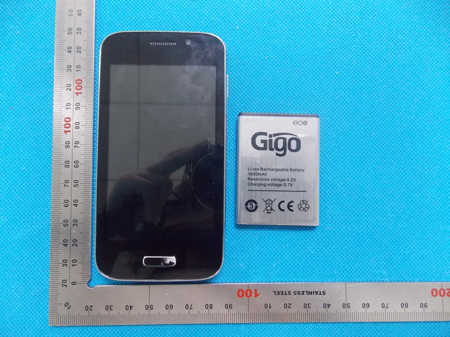
RWVCOBRA
Aug 28, 2013Mobile Phone
Equipment Class
PCE - PCS Licensed Transmitter held to ear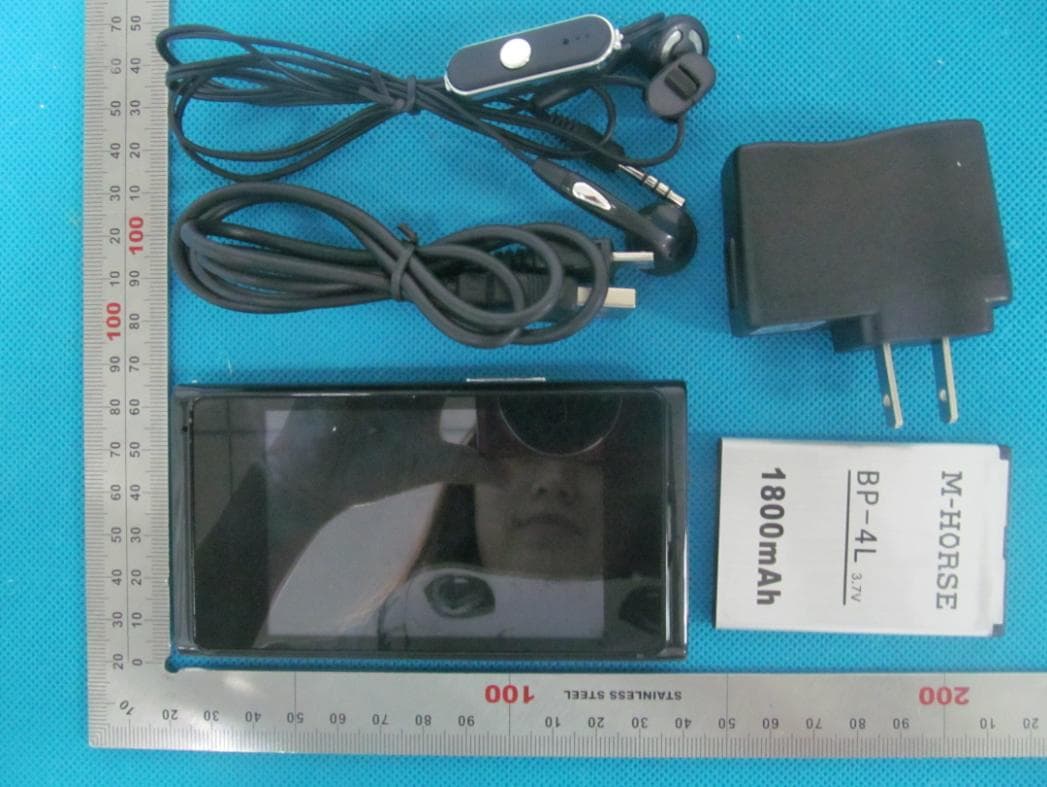
RWVNITRO
Jul 18, 2013Mobile Phone
Equipment Class
PCE - PCS Licensed Transmitter held to ear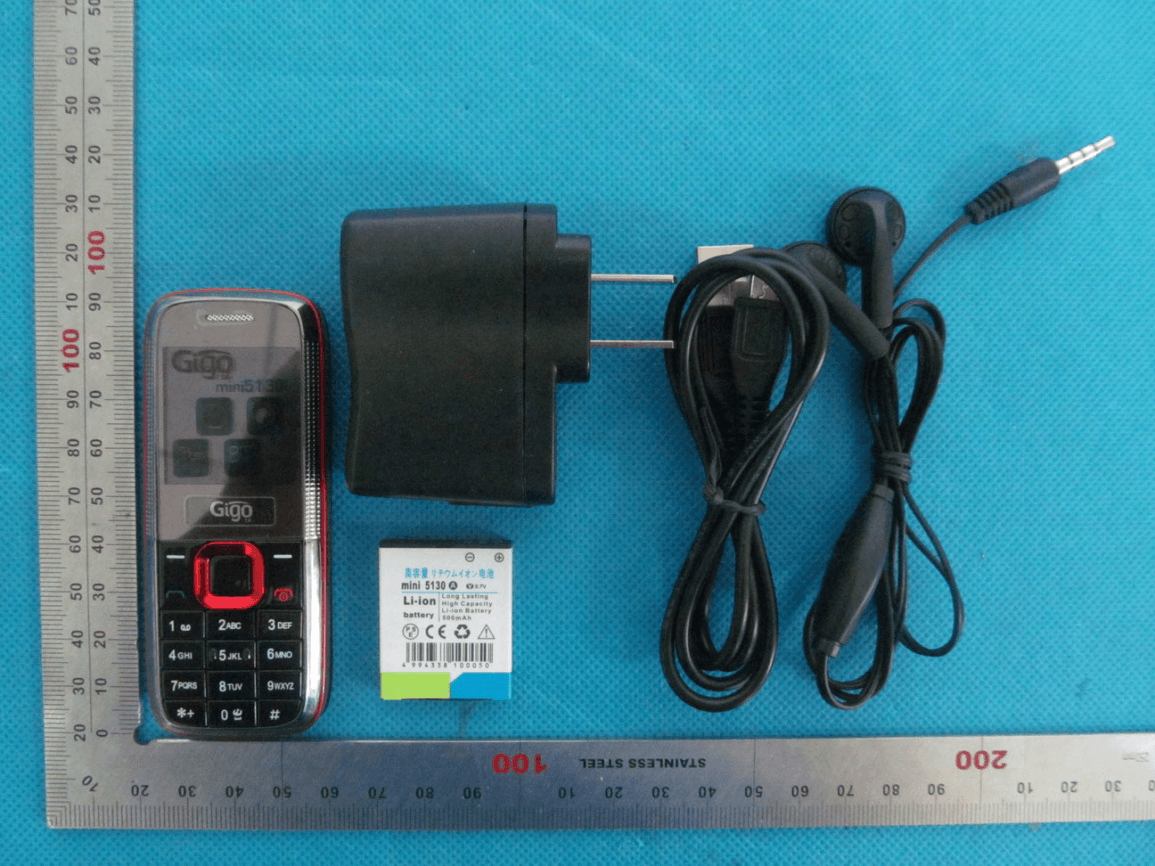
RWVMINI5130
May 13, 2013GSM Mobile Phone
Equipment Class
DSS - Part 15 Spread Spectrum Transmitter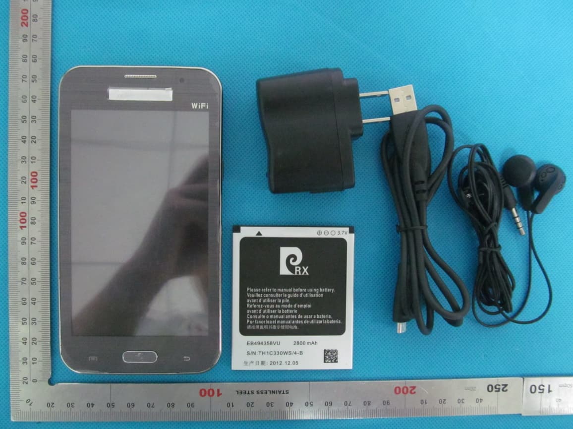
RWV7100
Mar 21, 2013GSM Mobile Phone
Equipment Class
DSS - Part 15 Spread Spectrum Transmitter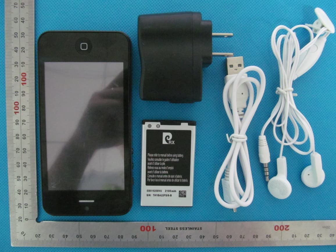
RWVI5
Mar 21, 2013Mobile Phone
Equipment Class
PCE - PCS Licensed Transmitter held to ear