RX2503-00-154Vehicle Immobilizer
Marelli Europe S.p.A.
Click to zoom
Application Details
- Equipment Class
- DCD - Part 15 Low Power Transmitter Below 1705 kHz
- Date of Grant
- Oct 07, 2007
- Application Purpose
- Original Equipment
- Date of Application
- Oct 07, 2007
- Equipment Note
- Vehicle Immobilizer
- Frequency Range
- 0.12500000 - 0.12500000
- Company
- Marelli Europe S.p.A.
- Country
- Italy
Documents & Files
Document Text
Text extracted from the exhibit documents filed with the FCC. Open a document above to read the original.
Users Manual
SITEMI ELETTRONICI 503.00.154 Page 1 of 3 Version 0 06.06.2007 Product description and Technical specification Type 503.00.154 Panel instrument with integrated immobiliser for VW group application Abstract This document summaries the technical characteristics of the device providing information of both a specific and a general nature. SITEMI ELETTRONICI 503.00.154 Page 1 of 3 Version 0 06.06.2007 1. Main Performance The Immobilizer built in the instrument panel has to read out the data code from a Transponder, located inside the key, and checks whether that key is authorized to start the engine of the vehicle. In case of an authorized key, a start-enable code is sent to the requested Engine Management System (EMS) via CAN-line. Else, the starting of the engine is disabled by sending a negative answer to the request of the EMS. 2. System Components 2.1 Transponder inside key The Transponder is composed of a receiver/transmitter coil and an electronic circuit, featuring rectifier, voltage regulator, sequencer and memory. The Transponder is power-supplied by means of the 125kHz electro-magnetic field. The Crypt-(security)-Transponder is based on a bidirectional communication (amplitude modulation and demodulation). 2.2 Transmitter/Receiver coil (Antenna) at the ignition lock The Antenna supplies the transponder with energy, sends commands and data to the Transponder and receives codes from the transponder. 2.3 Immobilizer part of the instrument panel The Immobilizer unit of the instrument panel is directly connected to the Immobilizer Antenna and stores the authorised key codes in a non-volatile memory. The instrument panel is permanently supplied with battery voltage (KL30). The Immobilizer function operates with ignition (KL15) on. 3. Normal Starting Sequence 1. Initialize the immobilizer function of the immobiliser built in the instrument panel at the key on (ignition, KL15 on) 2. The 125kHz electromagnetic field is switched on 3. The Immobilizer read out the fixcode of the Transponder 4. If the fixcode is recognized a bidirectional authentication protocol is proceeded with the engine control unit (max. 300ms) 5. The received authentication code is verified 6. If the verification procedure is passed , wait for request from engine control unit SITEMI ELETTRONICI 503.00.154 Page 1 of 3 Version 0 06.06.2007 4. Pinning of the instrument panel with immobilizer unit P13-7 coil P13-8 coil P13-12 CAN (H) P13-13 CAN (L) P13-1 Ignition key (KL15) P13-2 Battery Voltage (KL30) P13-19 GND Block diagram for the instrument panel with immobilizer unit 6. Electric specification’s Clock frequency : 32 MHz Power supply : 13,5V (vehicle battery) Foundmental immobiliser frequency : 125 kHz Antenna coil loop number : 131 Resistance : 40Ω @ 25°C 1kHz Inductance : 1,613 mH @25°C 1kHz Antenna for Immobilizer Instrument panel Key with Transponder Immo- bilizer unit To ECU
Cover Letter(s)
Corbetta 28/08/2007 Federal Communications Commission 7435 Oakland Mills Road Columbia, MD 21046 Gentlemen: This letter is to comply with Section 0.457(d)(2)(i) pertaining to confidential material. 503.00.154 would like the following documents regarding this submission for FCC ID: RX2503-00-154 to be kept confidential. 1. Schematic diagram 2. Block diagram The above material contains trade secrets or technical data, which would customarily be guarded from competitors. We do not want these documents to be accessible to the general public. Sincerely, Magneti Marelli Sistemi Elettronici S.p.A.
Cover Letter(s)
Corbetta 06/07/2007 User Manual Statement Letter Federal Communications Commission 7435 Oakland Mills Road Columbia, MD 21046 Ref.: FCC ID: RX2503.00.154 Radio equipment authorization by FCC in USA for Vehicle immobilizer 503.00.154 Dear Sirs The vehicle immobilizer will be supplied as an original equipment device to the car manufacturer. According to 47 CFR 15.19 (Labeling requirements) the car manufacturer will print the following text in the appropriate User Manuel of the car: “This device complies with part 15 of the FCC Rules. Operation is subject to the following two conditions: (1) This device may not cause harmful interference and (2) this device must accept any interference received, including interference that may cause undesired operation.” Changes or modifications to this unit not expressly approved by the party responsible for compliance could void the user’s authority to operate the equipment. Sincerely, Magneti Marelli Sistemi Elettronici S.p.A.
ID Label/Location Info
LABEL HERE
ID Label/Location Info
LABEL HERE
Operational Description
SITEMI ELETTRONICI 503.00.154 Page 1 of 3 Version 0 06.06.2007 Product description and Technical specification Type 503.00.154 Panel instrument with integrated immobiliser for VW group application Abstract This document summaries the technical characteristics of the device providing information of both a specific and a general nature. SITEMI ELETTRONICI 503.00.154 Page 1 of 3 Version 0 06.06.2007 1. Main Performance The Immobilizer built in the instrument panel has to read out the data code from a Transponder, located inside the key, and checks whether that key is authorized to start the engine of the vehicle. In case of an authorized key, a start-enable code is sent to the requested Engine Management System (EMS) via CAN-line. Else, the starting of the engine is disabled by sending a negative answer to the request of the EMS. 2. System Components 2.1 Transponder inside key The Transponder is composed of a receiver/transmitter coil and an electronic circuit, featuring rectifier, voltage regulator, sequencer and memory. The Transponder is power-supplied by means of the 125kHz electro-magnetic field. The Crypt-(security)-Transponder is based on a bidirectional communication (amplitude modulation and demodulation). 2.2 Transmitter/Receiver coil (Antenna) at the ignition lock The Antenna supplies the transponder with energy, sends commands and data to the Transponder and receives codes from the transponder. 2.3 Immobilizer part of the instrument panel The Immobilizer unit of the instrument panel is directly connected to the Immobilizer Antenna and stores the authorised key codes in a non-volatile memory. The instrument panel is permanently supplied with battery voltage (KL30). The Immobilizer function operates with ignition (KL15) on. 3. Normal Starting Sequence 1. Initialize the immobilizer function of the immobiliser built in the instrument panel at the key on (ignition, KL15 on) 2. The 125kHz electromagnetic field is switched on 3. The Immobilizer read out the fixcode of the Transponder 4. If the fixcode is recognized a bidirectional authentication protocol is proceeded with the engine control unit (max. 300ms) 5. The received authentication code is verified 6. If the verification procedure is passed , wait for request from engine control unit SITEMI ELETTRONICI 503.00.154 Page 1 of 3 Version 0 06.06.2007 4. Pinning of the instrument panel with immobilizer unit P13-7 coil P13-8 coil P13-12 CAN (H) P13-13 CAN (L) P13-1 Ignition key (KL15) P13-2 Battery Voltage (KL30) P13-19 GND Block diagram for the instrument panel with immobilizer unit 6. Electric specification’s Clock frequency : 32 MHz Power supply : 13,5V (vehicle battery) Foundmental immobiliser frequency : 125 kHz Antenna coil loop number : 131 Resistance : 40Ω @ 25°C 1kHz Inductance : 1,613 mH @25°C 1kHz Antenna for Immobilizer Instrument panel Key with Transponder Immo- bilizer unit To ECU
Test Report
Senton GmbH Aeussere Fruehlingstrasse 45 D-94315 Straubing Note: The test data of this report is related only to the individual item which has been tested. This report shall not be reproduced except in full extent without the written approval of the testing laboratory. Test Report No. 55147-070295-2 (Edition 1) Page 1 of 35 Pages Straubing, 18 April 2007 T E S T - R E P O R T No. 55147-070295-2 (Edition 1) for 503.00.154 (PQ35) Inductive TAG Reader - Vehicle Immobilizer Applicant: Magneti Marelli Sistemi Elettronici S.p.A. Test Specifications: FCC Code of Federal Regulations, CFR 47, Part 15, Sections 15.205, 15.207 and 15.209 Industry Canada Radio Standards Specifications RSS-Gen Issue 1, Section 7.2.2 and RSS-210 Issue 6, Sections 2.2, 2.6 (Category I Equipment) Senton GmbH Aeussere Fruehlingstrasse 45 D-94315 Straubing Test Report No. 55147-070295-2 (Edition 1) Page 2 of 35 Pages Table of Contents 1 Description of the Equipment Under Test (EUT) ........................................................ 3 2 Administrative Data..................................................................................................... 4 3 Identification of the Test Laboratory ........................................................................... 5 4 Summary .................................................................................................................... 6 5 Operation Mode and Configuration of EUT................................................................. 7 6 Measurement Procedures........................................................................................... 8 6.1 Bandwidth Measurements .................................................................................... 8 6.2 Radiated Emission Measurement 9 kHz to 30 MHz ............................................. 9 6.3 Radiated Emission in Fully or Semi Anechoic Room.......................................... 11 6.4 Radiated Emission at Open Field Test Site........................................................ 13 7 Photographs Taken During Testing .......................................................................... 14 8 Test Results for Transmitter ..................................................................................... 20 8.1 Occupied Bandwidth........................................................................................... 22 8.2 Designation of Emissions ................................................................................... 26 8.3 Restricted Bands of Operation ........................................................................... 27 8.4 Radiated Emission Measurement 9 kHz to 30 MHz .......................................... 28 8.5 Radiated Emission Measurement 30 MHz to 1 GHz ......................................... 29 8.6 Exposure of Humans to RF Fields...................................................................... 31 9 Referenced Regulations ........................................................................................... 33 10 Revision History ........................................................................................................ 34 11 Charts taken during testing ....................................................................................... 35 Senton GmbH Aeussere Fruehlingstrasse 45 D-94315 Straubing Test Report No. 55147-070295-2 (Edition 1) Page 3 of 35 Pages 1 Description of the Equipment Under Test (EUT) General data of EUT Type designation 1 : 503.00.154 (PQ35) Parts 2 : Serial number(s): --- Manufacturer: Magneti Marelli Sistemi Elettronici S.p.A. Type of equipment: Inductive TAG Reader - Vehicle Immobilizer Version: Series version FCC ID: Additional parts/accessories: Technical data of EUT Application frequency range: 119 kHz - 135 kHz Frequency range: 119 kHz - 135 kHz Operating frequency: 125.56 kHz Type of modulation: ASK Number of RF-channels: 1 Channel spacing: -- Designation of emissions 3 : 2K0A1D Type of antenna: Inductive loop Size/length of antenna: 0.0009 m 2 Connection of antenna: detachable not detachable Type of power supply: Battery supply Specifications for power supply: nominal voltage: 12.0 V minimum voltage: 10.8 V maximum voltage: 15.6 V nominal frequency: 0 Hz 1 Type designation of the system if EUT consists of more than one part. 2 Type designations of the parts of the system, if applicable. 3 Also known as "Class of Emission". Senton GmbH Aeussere Fruehlingstrasse 45 D-94315 Straubing Test Report No. 55147-070295-2 (Edition 1) Page 4 of 35 Pages 2 Administrative Data Application details Applicant (full address): Magneti Marelli Sistemi Elettronici S.p.A. Via.le A. Borletti, 61/63 20011 Corbetta (MI) ITALY Contract identification: Order No. 07/0069 Receipt of EUT: 11 April 2007 Date(s) of test: 13 April 2007 Note(s): Report details Report number: 55147-070295-2 Edition: 1 Issue date: 18 April 2007 Senton GmbH Aeussere Fruehlingstrasse 45 D-94315 Straubing Test Report No. 55147-070295-2 (Edition 1) Page 5 of 35 Pages 3 Identification of the Test Laboratory Details of the Test Laboratory Company name: Senton GmbH EMI/EMC Test Center Address: Aeussere Fruehlingstrasse 45 D-94315 Straubing Germany Laboratory accreditation: DAR-Registration No. DAT-P-171/94-02 FCC test site registration number 90926 Industry Canada test site registration: IC 3050 Contact person: Mr. Johann Roidt Phone: (+49) (0)9421 5522-0 Fax: (+49) (0)9421 5522-99 Senton GmbH Aeussere Fruehlingstrasse 45 D-94315 Straubing Test Report No. 55147-070295-2 (Edition 1) Page 6 of 35 Pages 4 Summary Summary of test results The tested sample complies with the requirements set forth in the Code of Federal Regulations CFR 47, Part 15, Sections 15.205 and 15.209 of the Federal Communication Commission (FCC) and the Radio Standards Specifications RSS-210 Issue 6, Sections 2.2, 2.6 (Category I Equipment) of Industry Canada (IC). Personnel involved in this report Laboratory Manager: Mr. Johann Roidt Responsible for testing: Mr.…
Text truncated - open the document above for the full version.
Contact Information
Applicant
Andrea Gozzo(Mr.)
Test Firm
TUV SUD Product Service GmbH PS-EMC-STRRainer Heller
Technical Specifications
| # | Rule Parts | Frequency Range | Power Output |
|---|---|---|---|
| 1 | 15C | 0.125 MHz - 0.125 MHz | - |
Other Applications from Marelli Europe S.p.A.
RX2HUAIDP21BY
Aug 11, 2024Infotainment Head Unit
Equipment Class
NII - Unlicensed National Information Infrastructure TXRX2HUAIDP20BY
Apr 10, 2024Infotainment Head Unit
Equipment Class
NII - Unlicensed National Information Infrastructure TX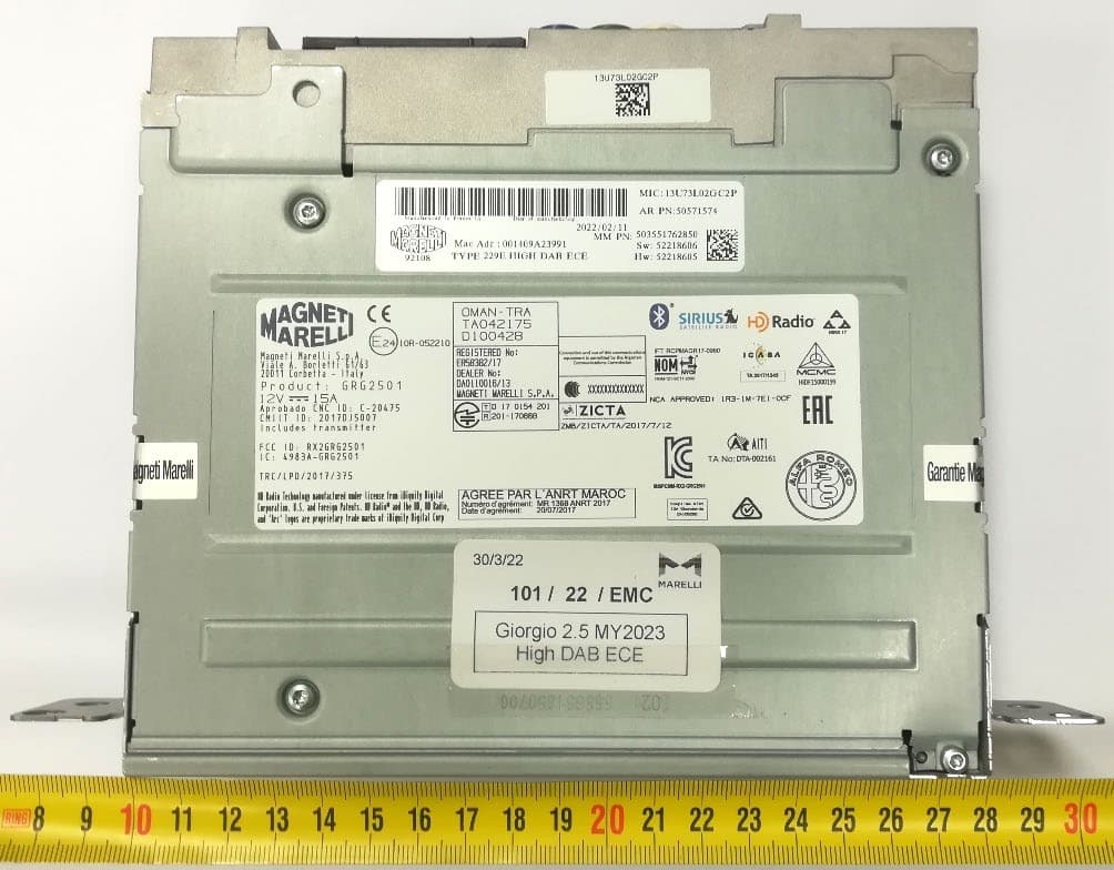
RX2GRG2501MY23
Jan 08, 2023Giorgio 2.5
Equipment Class
DSS - Part 15 Spread Spectrum Transmitter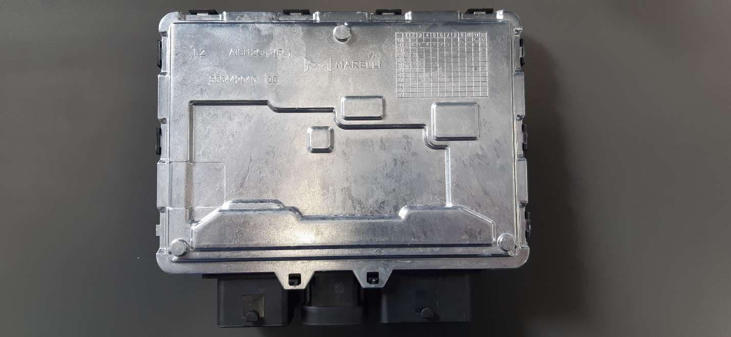
RX2BHD21
Apr 18, 2021Body Coputer Module
Equipment Class
DCD - Part 15 Low Power Transmitter Below 1705 kHz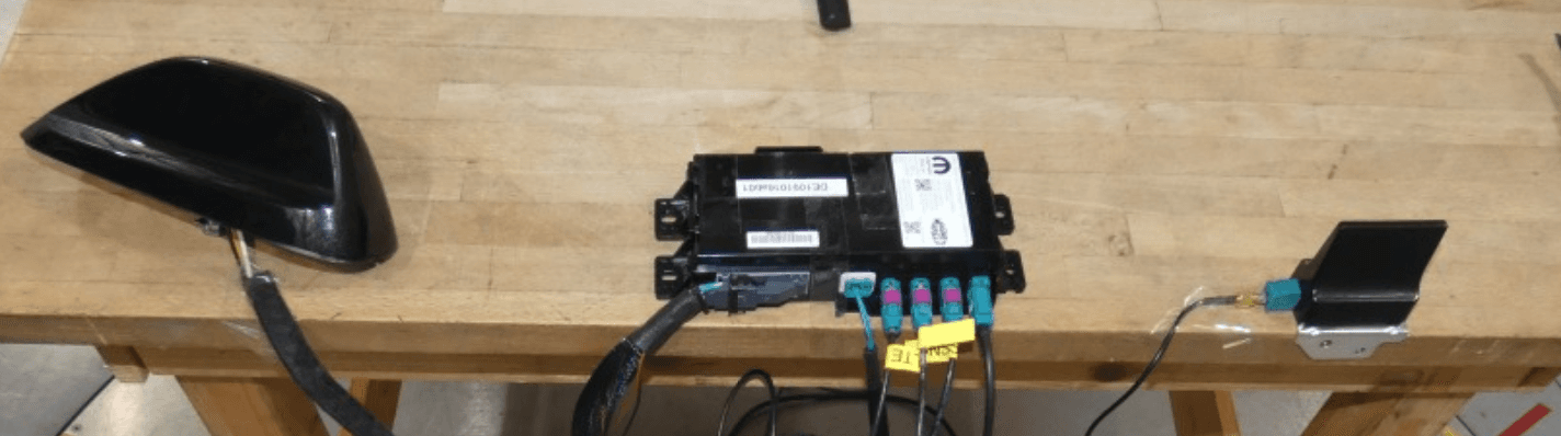
RX2TBTBMF30B0
Dec 21, 2020Telematic Control Unit
Equipment Class
DTS - Digital Transmission System