RX2EN1Bluetooth/WLAN Module
Marelli Europe S.p.A.Application Details
- Equipment Class
- DTS - Digital Transmission System
- Date of Grant
- Apr 03, 2013
- Application Purpose
- Original Equipment
- Date of Application
- Apr 02, 2013
- Equipment Note
- Bluetooth/WLAN Module
- Frequency Range
- 2412.00000000 - 2462.00000000
- Company
- Marelli Europe S.p.A.
- Country
- Italy
Documents & Files
Document Text
Text extracted from the exhibit documents filed with the FCC. Open a document above to read the original.
Users Manual
To Whom It May Concern: FCC ID: RX2EN1 IC: 4983A-EN1 The Bluetooth/WLAN Module “EN1” is for OEM installation only. When integrating the Module into the end product, the final user manual of the end product will include the following statements for FCC approval: The end product has to be labeled as follows: CONTAINS FCC ID: RX2EN1 FCC § 15.19 Labelling requirements This device complies with part 15 of the FCC Rules and Industry Canada license-exempt RSS standard(s). Operation is subject to the following two conditions: (1) This device may not cause harmful interference, and (2) this device must accept any interference received, including interference that may cause undesired operation. FCC § 15.21 Information to user Changes or modifications not expressly approved by the party responsible for compliance could void the user’s authority to operate the equipment. RF Exposure Requirements To comply with FCC RF exposure compliance requirements, the device must be installed to provide a separation distance of at least 20 cm from all persons. The Bluetooth/ WLAN Module “EN1” is for OEM installation only. When integrating the Module in the in the end product, the end product and the final user manual of the end product will include the following statements for Industry Canada approval: The end product has to be labeled as follows: CONTAINS IC: 4983A-EN1 INDUSTRY CANADA Statements Le présent appareil est conforme aux CNR d'Industrie Canada applicables aux appareils radio exempts de licence. L'exploitation est autorisée aux deux conditions suivantes : (1) l'appareil ne doit pas produire de brouillage, et (2) l'utilisateur de l'appareil doit accepter tout brouillage radioélectrique subi, même si le brouillage est susceptible d'en compromettre le fonctionnement. RF Exposure Requirements This equipment complies with Canada radiation exposure limits set forth for an uncontrolled environment. This equipment should be installed and operated with minimum distance 20cm between the radiator and your body. Déclaration d’exposition aux radiations: Cet équipement est conforme aux limites d’exposition aux rayonnements IC établies pour un environnement non contrôlé. Cet équipement doit être installé et utilisé avec un minimum de 20 cm de distance entre la source de rayonnement et votre corps. i.V. Signature Carsten Steinröder on behalf of Magneti Marelli S.p.A. 7Layers AG Viale C. Emanuele II, 150 Borsigstr.11 10078 Venaria 40880 Ratingen ITALY Germany
Users Manual
Bluetooth audio Overview ▷ Playback of music files from external devi‐ ces such as audio devices or mobile phones via Bluetooth is possible. ▷ The sound output is via the vehicle loud‐ speakers. ▷ The volume of the sound output depends on the device. If applicable, change volume set‐ tings on the device. ▷ Up to four external devices can be registered with the vehicle. Requirements ▷ Suitable device. Visit www.bmw.com/blue‐ tooth for more information. ▷ Device ready for operation. ▷ Ignition switched on. ▷ Bluetooth in the vehicle, see page 79, and device activated. ▷ Bluetooth presettings must be made on the device, for example connect without confir‐ mation or visibility, see Owner's Handbook of the device. ▷ A number with a minimum of 4 and a maxi‐ mum 16 positions is specified as the Blue‐ tooth passkey. Only required for non-recur‐ ring registration. ▷ Vehicle is at rest. Connecting Connecting the device Only connect the device when the vehicle is stationary. Otherwise, you may become dis‐ tracted and endanger the vehicle occupants and other road users.◀ 1. "Settings" 2. "Connections" 3. "Bluetooth" 4. "Add new device" The Bluetooth name of the vehicle is dis‐ played in the control display. 5. To perform other operations on the device; see the Owner's Handbook of the device: for example finding/connecting Bluetooth de‐ vice or new device. The Bluetooth name of the vehicle is shown on the display of the device. 6. Select the Bluetooth name of the vehicle on the display of the device. 7. Request using the iDrive or mobile phone to enter the same Bluetooth passkey. Enter and confirm passkey. Or Compare the control number in the vehicle display with the control number in the mo‐ bile phone display. Confirm the control num‐ ber in the mobile phone and on the vehicle. "OK" 8. Select functions for which the device is to be used, for example "Bluetooth audio". 9. "OK" If connection was successful, the device is shown as connected. White symbol: device active as audio source. If connection was unsuccessful: What to do if..., see page 62. Seite 60 EntertainmentExternal devices 60 Online Edition for Part no. 01 40 2 917 877 - II/13 Connecting a certain device An already connected device can be connected as an active audio source. Connection not possible if data is exchanged using a mobile phone equipped with Bluetooth. Requirements If necessary, activate the audio connection of the desired device from the list of connected devices. 1. "Settings" 2. "Connections" 3. "Bluetooth" 4. Call up "Options". 5. "Configure device" 6. "Audio" 7. "OK" Connecting a device 1. "Settings" 2. "Connections" 3. "Bluetooth" 4. Select the device to be connected. White symbol: device active as audio source. Playback General ▷ The following functions are dependent on the device: display of track information, fast forward/rewind, random playback. ▷ Can be operated using the device or iDrive. ▷ Playback is interrupted if data is exchanged using a mobile phone equipped with Blue‐ tooth. Starting play 1. Connecting a device. 2. "Multimedia" 3. "External devices" 4. Select the symbol. Playback is automatically started. Changing the track Not all functions may be available, depending on the device. SymbolFunction Next track Previous title Fast forward/rewind Keep button pressed. Random playback 1. "Multimedia" 2. "External devices" 3. Select the symbol. 4. Call up "Options". 5. "Random" Disconnecting audio connection 1. "Settings" 2. "Connections" 3. "Bluetooth" 4. Highlight the desired device. 5. Call up "Options". 6. "Configure device" Seite 61 External devicesEntertainment 61 Online Edition for Part no. 01 40 2 917 877 - II/13 7. "Audio" 8. "OK" Disconnecting a device 1. "Settings" 2. "Connections" 3. "Bluetooth" 4. Highlight the device to be disconnected. 5. Call up "Options". 6. "Delete device" What to do if... Visit www.bmw.com/bluetooth for more infor‐ mation on compatible devices. Device not supported by the vehicle. ▷ If applicable, perform a software update, see page 62. Device not registered or paired. ▷ Do the Bluetooth passkeys for device and vehicle match. Enter the same passkey on the device and using iDrive. ▷ Duration for passkey input longer than 30 seconds. Repeat the connection at‐ tempt. ▷ Is the mobile phone in power-save mode or is the battery low? Charge the mobile phone using the snap-in adapter or the charging cable. ▷ Is the device no longer responding. Switch the device off and on again. ▷ Repeat the connection attempt. No music can be played back. ▷ Start the program for playing back music files on the device and if necessary, select a track via the device. ▷ Switch the radio off and on again. Music files are played back, but only at low vol‐ ume. ▷ Adjust the volume controls on the device. Playback is disrupted when a button is pressed on the device or if other messages are issued via the device. ▷ Switch off keypad acknowledgement tones and other audio output at the device. Playback is interrupted by phone calls or traffic announcements and does not resume automat‐ ically. ▷ Switch the radio off and on again. Playback is not possible if the mobile phone is connected via Bluetooth Audio and via the USB interface or snap-in adapter at the same time. ▷ Disconnect one of the two pairing connec‐ tions, for example disconnect audio connec‐ tion, see page 61, and restart playback. If all the points on the list have been reviewed and the desired function cannot be run, contact Hotline or Service Centre. Seite 62 EntertainmentExternal devices 62 Online Edition for Part no. 01 40 2 917 877 - II/13 Telephone Vehicle Equipment This chapter describes all standard, national and special equipment provided in the model series. Therefore equipment not available in a vehicle is also described, for example the selected special equipment or national version. That also applies to safety-relevant functions and systems. Principle Mobiles or other external devices, for example audio player, can be connected to the v…
Text truncated - open the document above for the full version.
Cover Letter(s)
RF_160, Issue 03 Declaration of Authorization We Name: Magneti Marelli S.p.A. Address: Viale A. Borletti, 61/63 City: 20011 Corbetta Country: Italy Declare that: Name Representative of agents: Carsten Steinröder / Abdellah Ahakki / Imad Hjije Agent Company name: 7Layers AG Address: Borsigstr.11 City: 40880 Ratingen Country Germany is authorized to apply for Certification of the following product(s): Product description: Bluetooth/WLAN Module Type designation: EN1 Trademark: Magneti Marelli on our behalf. Date: 22 March 2013 City: Corbetta Name: Giuseppe Bergamaschi Function: BL Electronics Quality Director Signature: ............................... Notes: (1): Required for FCC application (2): For FCC it must be the Grantee Code “owner” or the authorized agent.
Cover Letter(s)
RF_734_00, Issue 1 Modular Approval Request FCC (per DA 00-1407) FCC ID: RX2EN1 Items to be covered Answer from applicant 1. The modular transmitter must have its own RF shielding. NO shielding available 2. The modular transmitter must have buffered modulation/data inputs (if such inputs are provided) to ensure that the module will comply with Part 15 requirements under conditions of excessive data rates or over-modulation. YES 3. The modular transmitter must have its own power supply regulation. YES 4. The modular transmitter must comply with the antenna requirements of Section 15.203 and 15.204(c). The antenna must either be permanently attached or employ a “unique” antenna coupler (at all connections between the module and the antenna, including the cable).. YES 5. The modular transmitter must be tested in a stand-alone configuration, i.e., the module must not be inside another device during testing. This is intended to demonstrate that the module is capable of complying with Part 15 emission limits regardless of the device into which it is eventually installed. NO, the testing has been performed inside a specific host (only OEM installation allowed) 6. The modular transmitter must be labeled with its own FCC ID number, and, if the FCC ID is not visible when the module is installed inside another device, then the outside of the device into which the module is installed must also display a label referring to the enclosed module. This exterior label can use wording such as the following: “Contains Transmitter Module FCC ID: XYZMODEL1” or “Contains FCC ID: XYZMODEL1.” Any similar wording that expresses the same meaning may be used. The Grantee may either provide such a label, an example of which must be included in the application for equipment authorization, or, must provide adequate instructions along with the module which explain this requirement. In the latter case, a copy of these instructions must be included in the application for equipment authorization. YES 7. The modular transmitter must comply with any specific rule or operating requirements applicable to the transmitter and the manufacturer must provide adequate instructions along with the module to explain any such requirements. A copy of these instructions must be included in the application for equipment authorization. For example, there are very strict operational and timing requirements that must be met before a transmitter is authorized for operation under Section 15.231. For instance, data transmission is prohibited, except for operation under Section 15.231(e), in which case there are separate field strength level and timing requirements. Compliance with these requirements must be assured. YES 8. The modular transmitter must comply with any applicable RF exposure requirements. For example, FCC Rules in Sections 2.1091, 2.1093 and specific Sections of Part 15, including 15.319(i), 15.407(f), 15.253(f) and 15.255(g), require that Unlicensed PCS, UNII and millimeter wave devices perform routine environmental evaluation for RF Exposure to demonstrate compliance. In addition, spread spectrum transmitters operating under Section 15.247 are required to address RF Exposure compliance in accordance with Section 15.247(b)(4). Modular transmitters approved under other Sections of Part 15, when necessary, may also need to address certain RF Exposure concerns, typically by providing specific installation and operating instructions for users, installers and other interested parties to ensure compliance. YES Note: If compliance with one or more of the numbered requirements, listed above, cannot be demonstrated, it may be possible to obtain a “Limited Modular Approval” (LMA). Name and surname of applicant (or Name and surname of applicant (or Name and surname of applicant (or Name and surname of applicant (or authorized authorizedauthorized authorized representative): representative): representative): representative): Carsten Steinröder Carsten SteinröderCarsten Steinröder Carsten Steinröder Date: Date: Date: Date: 3/13/2013 3/13/20133/13/2013 3/13/2013 Signature: __ Signature: __Signature: __ Signature: __i.V. i.V.i.V. i.V._______________________ ______________________________________________ _________________________ ____ __
Test Report
Antenna Information Antenna Type: External Cableantenna Antenna Connector: Fakra Max. Gain: -2 dBi Manufacturer: Magneti Marelli 0,05,0 10,015,020,025,030,035,0 0 10 20 30 40 50 60 70 80 90 270 280 290 300 310 320 330 340 350 2,40GHz2,44GHz2,48GHzMittelwert BMW Antennenvermessung EI-41Messobjekt:BT Kabelantenne in MALMittelwert: 20,0dBμV 100 110 120 130 140 150 160 170 180 190 200 210 220 230 240 250 260 Mittelwert
Test Report
Final Report on EN1 FCC ID: RX2EN1 MDE_MAGNET_1201_FCCa acc. Title 47 CFR chapter I part 15 subpart C Report Reference: February 15, 2013Date: Test Laboratory: 7Layers AG Borsigstr. 11 40880 Ratingen Germany Note: The following test results relate only to the devices specified in this document. This report shall not be reproduced in parts without the written approval of the test laboratory. 7Layers AG Aufsichtsratsvorsitzender h Registergerichth registered in: Borsigstrasse 11 Chairman of the Supervisory Board: Düsseldorf, HRB 44096 40880 Ratingen, Germany Ralf Mertens USt-IdNr h VAT No.: Phone: +49 (0) 2102 749 0 Vorstandh Board: DE 203159652 Fax: +49 (0) 2102 749 350 Dr. H.-J. Meckelburg TAX No. 147/5869/0385 www.7Layers.com Reference: MDE_MAGNET_1201_FCCa acc. Title 47 CFR chapter I part 15 subpart C 1Administrative Data 1.1 Project Data Abdellah AhakkiProject Responsible: 2013/02/15Date Of Test Report: 2012/12/05Date of first test: 2013/02/07Date of last test: 1.2 Applicant Data Company Name:Magneti Marelli S.p.A. Viale C. Emanuele II, 150Street: 10078 Venaria City: ItalyCountry: Contact Person:Mr. Franco Schinco EMC & Type Approvals ManagerFunction: Infotainment & TelematicsDepartment: +39-011-6879.977Phone: +39-011-6879.199Fax: [email protected]: 1.3 Test Laboratory Data The following list shows all places and laboratories involved for test result generation: 7 layers DE Company Name :7 layers AG Street :Borsigstrasse 11 City :40880 Ratingen Country :Germany Contact Person :Mr. Michael Albert Phone :+49 2102 749 201 Fax :+49 2102 749 444 E Mail :[email protected] Laboratory Details Accreditation InfoLab IDIdentificationResponsible DAkkS-Registration no. D-PL-12140-01-01Radiated EmissionsLab 1Mr. Robert Machulec Mr. Andreas Petz DAkkS-Registration no. D-PL-12140-01-01Regulatory Bluetooth RF Test Solution Lab 2Mr. Jimmy Chatheril Mr. Sören Berentzen Page 2 of 66 Reference: MDE_MAGNET_1201_FCCa acc. Title 47 CFR chapter I part 15 subpart C 2.2 Detailed Description of OUT Samples Sample : a01 OUT IdentifierEN1 Sample DescriptionSample#1 HW Status004.001.005 SW StatusTest SW Low VoltageLow Temp.6.5 V-40 °C High Temp.High Voltage16 V+65 °C Normal Temp.Nominal Voltage12 V23 °C Parameter List: ValueParameter Description Parameter for Scope FCC_v2 Antenna Gain-2 (dBi) Frequency_high2480 (MHz) Frequency_low2402 (MHz) Frequency_mid2441 (MHz) 2.3 OUT Features Features for OUT: EN1 Allowed ValuesDesignationDescriptionSupported Value(s) Features for scope: FCC_v2 BTEUT supports Bluetooth data rate of 1 Mbps with GFSK modulation in the band 2400 MHz - 2483.5 MHz DCThe OUT is powered by or connected to DC Mains Eantremovable antenna supplied and type tested with the radio equipment, designed as an indispensable part of the equipment EDR2EUT supports Bluetooth using data rate of 2 Mbps with PI/4 DQPSK modulation in the band 2400 MHz - 2483.5 MHz EDR3EUT supports Bluetooth using data rate of 3 Mbps with 8DPSK modulation in the band 2400 MHz - 2483.5 MHz PantCpermanent fixed antenna connector, which may be built-in, designed as an indispensable part of the equipment Page 4 of 66 Reference: MDE_MAGNET_1201_FCCa acc. Title 47 CFR chapter I part 15 subpart C 2.4 Setups used for Testing For each setup a relation is given to determine if and which samples and auxiliary equipment is used. The left side list all OUT samples and the right side lists all auxiliary equipment for the given setup. Sample No.Sample DescriptionAE No.AE Description Setup No. List of OUT samplesList of auxiliary equipment A01 a01Sample#1Sample: 3Results 3.1 General Available at the test laboratory. The results of the inspection are described on the following pages, where 'Conformity' or 'Passed' means that the certification criteria were verified and that the tested device is conform to the applied standard. In cases where 'Declaration' is printed, the required documents are available in the manufacturers product documentation. In cases where 'not applicable' is printed, the test case requirements are not relevant to the specific equipment implementation. Documentation of tested devices: Interpretation of the test results: 1) This test report focuses on the Bluetooth part of the device. 2) Special Software for testing: The OUT could be set into Bluetooth Test Modes by using the special test software which was installed on the OUT by applicant. The specific test modes could be set and controlled by the signalling unit "CBT" by Rohde&Schwarz over the air. 3) The laboratory environmental conditions are available and recorded in the Interlab System. Note: 3.2 List of the Applicable Body (Body for Scope: FCC_v2) DesignationDescription Subpart C - Intentional Radiators; 15.247 Operation within the bands 902-928 MHz, 2400-2483.5 MHz, and 5725-5850 MHz. FCC47CFRChIPART15c247RADIO FREQUENCY DEVICES 3.3 List of Test Specification Test Specification:FCC part 2 and 15 Version10-1-11 Edition Title:PART 2 - GENERAL RULES AND REGULATIONS PART 15 - RADIO FREQUENCY DEVICES Page 5 of 66 Reference: MDE_MAGNET_1201_FCCa acc. Title 47 CFR chapter I part 15 subpart C 3.4 Summary Test Case Identifier / Name SetupDate of TestResultTest (condition)Ref. Lab 15c.2 Spurious radiated emissions §15.247 (d), §15.35 (b), §15.209 15c.2; Frequency = 2402, Mode = BT transmit using 1 Mbps with GFSK modulation, Channel = low 2013/02/07A01Lab 1Passed 15c.2; Frequency = 2402, Mode = BT transmit using 2 Mbps with PI/4 DQPSK modulation 2013/02/07A01Lab 1Passed footnote: 3 15c.2; Frequency = 2402, Mode = BT transmit using 3 Mbps with 8DPSK modulation 2013/02/07A01Lab 1Passed footnote: 3 15c.2; Frequency = 2441, Mode = BT transmit using 1 Mbps with GFSK modulation, Channel = mid 2013/02/07A01Lab 1Passed 15c.2; Frequency = 2441, Mode = BT transmit using 2 Mbps with PI/4 DQPSK modulation 2013/02/07A01Lab 1Passed footnote: 3 15c.2; Frequency = 2441, Mode = BT transmit using 3 Mbps with 8DPSK modulation 2013/02/07A01Lab 1Passed footnote: 3 15c.2; Fr…
Text truncated - open the document above for the full version.
Test Report
Test Laboratory: Borsigstr. 11 Germany 7Layers AG 40880 Ratingen Note: The following test results relate only to the devices specified in this document. This report shall not be reproduced in parts without the written approval of the test laboratory. 7 layers AG Aufsichtsratsvorsitzender h Registergerichth registered in: Borsigstrasse 11 Chairman of the Supervisory Board: Düsseldorf, HRB 44096 40880 Ratingen, Germany Ralf Mertens USt-IdNr h VAT No.: Phone: +49 (0) 2102 749 0 Vorstandh Board: DE 203159652 Fax: +49 (0) 2102 749 350 Dr. H.-J. Meckelburg TAX No. 147/5869/0385 www.7Layers.com FCC Measurement/Technical Report on WLAN transceiver EN1 Report Reference: MDE_MAGNET_1201_FCCc Test report Reference: MDE_MAGNET_1201_FCCc Page 2 of 75 Table of Contents 0 Summary 3 0.1 Technical Report Summary 3 0.2 Measurement Summary 4 1 Administrative Data 6 1.1 Testing Laboratory 6 1.2 Project Data 6 1.3 Applicant Data 6 1.4 Manufacturer Data 6 2 Test object Data 7 2.1 General EUT Description 7 2.2 EUT Main components 8 2.3 Ancillary Equipment 8 2.4 Auxiliary Equipment 9 2.5 EUT Setups 9 2.6 Operating Modes 10 2.7 Product labelling 10 3 Test Results 11 3.1 Occupied bandwidth 11 3.2 Peak power output 14 3.3 Spurious RF conducted emissions 17 3.4 Spurious radiated emissions 21 3.5 Band edge compliance 27 3.6 Power density 31 4 Test Equipment 34 5 Photo Report 41 6 Setup Drawings 41 7 FCC and IC Correlation of measurement requirements 42 8 Annex measurement plots 43 8.1 Occupied bandwidth 43 8.2 Peak power output 49 8.3 Band edge compliance conducted and Spurious RF conducted emissions 55 8.4 Power density 70 Test report Reference: MDE_MAGNET_1201_FCCc Page 3 of 75 0 Summary 0.1 Technical Report Summary Type of Authorization Certification for an Intentional Radiator (Digital Device / Spread Spectrum). Applicable FCC Rules Prepared in accordance with the requirements of FCC Rules and Regulations as listed in 47 CFR Ch.1 Parts 2 (10-1-11 Edition) and 15 (10-1-11 Edition). The following subparts are applicable to the results in this test report. Part 2, Subpart J - Equipment Authorization Procedures, Certification Part 15, Subpart C – Intentional Radiators § 15.201 Equipment authorization requirement § 15.207 Conducted limits § 15.209 Radiated emission limits; general requirements § 15.247 Operation within the bands 902-928 MHz, 2400-2483.5 MHz and 5725-5850 MHz Note: The tests were selected and performed with reference to the FCC measurement guide line “Measurement of Digital Transmission Systems Operating under Section 15.247 October 4, 2012” Instead of applying ANSI C63.4–1992 which is referenced in the FCC Public Note, the newer ANSI C63.4–2009 is applied. Summary Test Results: The EUT complied with all performed tests as listed in chapter 0.2 Measurement Summary. Test report Reference: MDE_MAGNET_1201_FCCc Page 4 of 75 0.2 Measurement Summary FCC Part 15, Subpart C § 15.207 Conducted emissions (AC power line) The measurement was performed according to ANSI C63.4 2009 OP-Mode Setup Port Final Result op-mode 4 Setup_01 AC Port (power line) N/A FCC Part 15, Subpart C § 15.247 (a) (1) Occupied bandwidth The measurement was performed according to FCC § 15.31 10-1-11 Edition OP-Mode Setup Port Final Result op-mode 1b Setup_02 Perm.ant.connector passed op-mode 1g Setup_02 Perm.ant.connector passed op-mode 2b Setup_02 Perm.ant.connector passed op-mode 2g Setup_02 Perm.ant.connector passed op-mode 3b Setup_02 Perm.ant.connector passed op-mode 3g Setup_02 Perm.ant.connector passed FCC Part 15, Subpart C § 15.247 (b) (1) Peak power output The measurement was performed according to FCC § 15.31 10-1-11 Edition OP-Mode Setup Port Final Result op-mode 1b Setup_02 Perm.ant.connector passed op-mode 1g Setup_02 Perm.ant.connector passed op-mode 2b Setup_02 Perm.ant.connector passed op-mode 2g Setup_02 Perm.ant.connector passed op-mode 3b Setup_02 Perm.ant.connector passed op-mode 3g Setup_02 Perm.ant.connector passed FCC Part 15, Subpart C § 15.247 (d) Spurious RF conducted emissions The measurement was performed according to FCC § 15.31 10-1-11 Edition OP-Mode Setup Port Final Result op-mode 1b Setup_02 Perm.ant.connector passed op-mode 1g Setup_02 Perm.ant.connector passed op-mode 2b Setup_02 Perm.ant.connector passed op-mode 2g Setup_02 Perm.ant.connector passed op-mode 3b Setup_02 Perm.ant.connector passed op-mode 3g Setup_02 Perm.ant.connector passed Test report Reference: MDE_MAGNET_1201_FCCc Page 6 of 75 1 Administrative Data 1.1 Testing Laboratory Company Name: 7Layers AG Address Borsigstr. 11 40880 Ratingen Germany This facility has been fully described in a report submitted to the FCC and accepted under the registration number 96716 . The test facility is also accredited by the following accreditation organisation: Laboratory accreditation no.: DAkkS D-PL-12140-01-01 Responsible for Accreditation Scope: Dipl.-Ing. Bernhard Retka Dipl.-Ing. Robert Machulec Dipl.-Ing. Thomas Hoell Dipl.-Ing. Andreas Petz Report Template Version: 2012-03-14 1.2 Project Data Responsible for testing and report: Dipl.-Ing. Carsten Steinröder Date of Test(s): 2012-12-05 to 2013-01-27 Date of Report: 2013-02-21 1.3 Applicant Data Company Name: Magneti Marelli S.p.A. Address: Viale C. Emanuele II, 150 10078 Venaria (TO) Italy Contact Person: Mr. Franco Schinco 1.4 Manufacturer Data Company Name: please see applicant data Address: Contact Person: Test report Reference: MDE_MAGNET_1201_FCCc Page 7 of 75 2 Test object Data 2.1 General EUT Description Equipment under Test: WLAN transceiver (IEEE 802.11 b/g) Type Designation: EN1 Kind of Device: (optional) Car Radio Voltage Type: DC (Car Battery) Voltage Level: 12 V Tested Modulation Type: DBPSK; OFDM:BPSK; OFDM:64-QAM General product description: The WLAN (Wireless Local Area Network) Transceiver is operating in the 2.4 GHz ISM band in the range 2412.0 – 2462.0 MHz and uses the Direct Sequence Spread Spectrum (DSSS) Modulation. Specific product description for the EUT: The EUT is a car …
Text truncated - open the document above for the full version.
Test Report
7 layers AG Aufsichtsratsvorsitzenderh Registergerichth registered in: Borsigstrasse 11 Chairman of the Supervisory Board: Düsseldorf, HRB 44096 40880 Ratingen, Germany Markus Becker USt-IdNr h VAT Nr: Phone: +49 (0) 2102 749 0 Vorstandh Board: DE 203159652 Fax: +49 (0) 2102 749 350 Dr. Hans-Jürgen Meckelburg www.7Layers.com René Schildknecht Carsten Steinröder 19.03.13 Phone +49 (0) 2102 749 331 Fax +49 (0) 2102 749 350 FCC-ID : RX2EN1 Maximum Permissible Exposure calculation Dear Madams or Sirs, please find here our Maximum Permissible Exposure calculations for the Bluetooth/WLAN Module EN1. Best Regards i.V. Carsten Steinröder Telefication Edisonstr. 12a 6902 PK Zevenaar The Netherlands MDE_MAGNET_1201 - 2 - Maximum Permissible Exposure (as specified in Table 1B of 47 CFR 1.1310 – Limits for Maximum Permissible Exposure (MPE), Limits for General Population/Uncontrolled Exposure) Frequency range (MHz) Power density (mW/cm²) 300 – 1,500 f/1500 1,500 – 100,000 1.0 Calculations 2400-2483.5 MHz band Maximum peak output power at antenna input terminal for Bluetooth/WLAN module: 0.062 W Prediction distance R: 20 cm Prediction frequency: 2.4 GHz Prediction Antenna Gain G: -2.0 dBi (WiFi Antenna) MPE limit S: 1 mW/cm² Equation OET bulletin 65, page 18, edition 97-01: S = P*G / (4πR²) S = power density P = power input to the antenna G = power gain of the antenna in the direction of interest relative to an isotropic radiator R = distance to the centre of radiation of the antenna Maximum permissible power density: 0.0077 mW/cm² => Delta to MPE Limit: 0.9923 mW/cm²
Test Setup Photos
Test Laboratory: Borsigstr. 11 Germany 7Layers AG 40880 Ratingen Note: The following test results relate only to the devices specified in this document. This report shall not be reproduced in parts without the written approval of the test laboratory. 7Layers AG Aufsichtsratsvorsitzender h Registergerichth registered in: Borsigstrasse 11 Chairman of the Supervisory Board: Düsseldorf, HRB 44096 40880 Ratingen, Germany Markus Becker USt-IdNr h VAT No.: Phone: +49 (0) 2102 749 0 Vorstandh Board: DE 203159652 Fax: +49 (0) 2102 749 350 Dr. H.-J. Meckelburg TAX No. 147/5869/0385 www.7Layers.com Photo Report Bluetooth/WLAN transceiver EN1 Report Reference: MDE_MAGNET_1201_FCC_Photo Test report Reference: MDE_MAGNET_1201_FCC_Photo Page 2 of 3 1 Photo Report 1.1 Photos of test setups Photo 1: Test setup for radiated measurements (below 30 MHz) Test report Reference: MDE_MAGNET_1201_FCC_Photo Page 3 of 3 Photo 2: Test setup for radiated measurements (30 MHz to 1 GHz) Photo 3: Test setup for radiated measurements (above 1 GHz)
Contact Information
Applicant
Andrea Gozzo(Mr.)
Test Firm
7layers AGRobert Machulec
Technical Specifications
| # | Rule Parts | Frequency Range | Power Output |
|---|---|---|---|
| 2 | 15C | 2.41 GHz - 2.46 GHz | 62.00 mW |
Other Applications from Marelli Europe S.p.A.
RX2HUAIDP21BY
Aug 11, 2024Infotainment Head Unit
Equipment Class
NII - Unlicensed National Information Infrastructure TXRX2HUAIDP20BY
Apr 10, 2024Infotainment Head Unit
Equipment Class
NII - Unlicensed National Information Infrastructure TX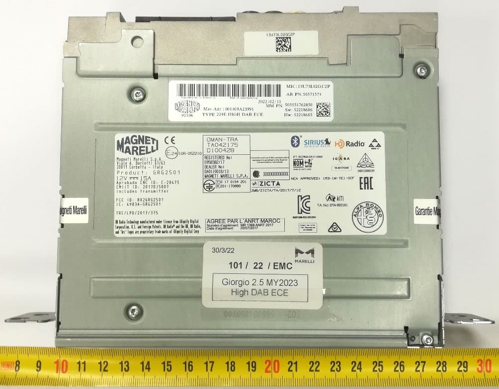
RX2GRG2501MY23
Jan 08, 2023Giorgio 2.5
Equipment Class
DSS - Part 15 Spread Spectrum Transmitter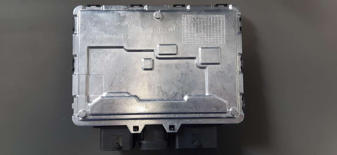
RX2BHD21
Apr 18, 2021Body Coputer Module
Equipment Class
DCD - Part 15 Low Power Transmitter Below 1705 kHz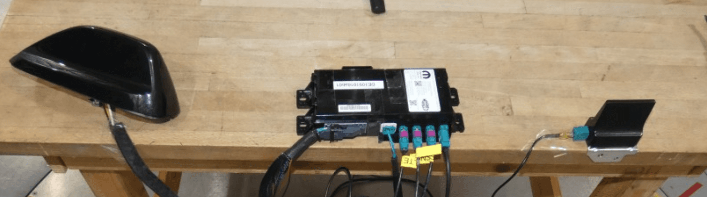
RX2TBTBMF30B0
Dec 21, 2020Telematic Control Unit
Equipment Class
DTS - Digital Transmission System