RX2NBCAI010Vehicle Immobilizer
Marelli Europe S.p.A.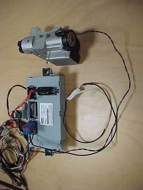
Click to zoom
Application Details
- Equipment Class
- CYY - Communications Receiver used w/Pt 15 Transmitter
- Date of Grant
- Feb 01, 2005
- Application Purpose
- Original Equipment
- Date of Application
- Feb 01, 2005
- Equipment Note
- Vehicle Immobilizer
- Frequency Range
- 433.92000000 - 433.92000000
- Company
- Marelli Europe S.p.A.
- Country
- Italy
Documents & Files
Document Text
Text extracted from the exhibit documents filed with the FCC. Open a document above to read the original.
Block Diagram
433. 9 2 M H z S A W Filt e r Re ce iv e r U 3741 B X3 6.76 43 75 M H z T r ansc e i v er PC F799 1 X1 4.00 M H z IN_ R XUHF POLL _U P Imm o b iliz e r Co il 125 kH z SER _IM M O _D A T A S E R _ I MMO _ C MD SER _IM M O _C LK Eng i ne co n t ro l un it CA N b u s M i cr opr ocessor Inpu t Outp ut Bu ffer s Latch es Ser i al Co mm a n d & Inter f ace Dri v e r Re la y s X2 4.00 M H z
Cover Letter(s)
Federal Communications Commission 7435 Oakland Mills Road Columbia, MD 21046 Gentlemen: This letter is to comply with Section 0.457(d)(2)(i) pertaining to confidential material. Magneti Marelli Sistemi Elettronici S.p.A. would like the following documents regarding this submission for FCC ID: RX2NBCAI010 to be kept confidential. 1. Pages 1 to 15 of document 541861211101 – Schematic Diagram The above material contains trade secrets or technical data, which would customarily be guarded from competitors. We do not want these documents to be accessible to the general public. Sincerely, Magneti Marelli Sistemi Elettronici S.p.A.
ID Label/Location Info
LABEL HERE
Operational Description
Sistemi Elettronici Viale Aldo BORLETTI 61/63 I-20011CORBETTA - MI Tel +39-02.9722.1 Document No.: 09/2004 Page 1/3 Version 01 Date: 04-09-20 Product description and Technical specification Type BCAI010 Immobiliser for FIAT AUTO 137/139 Abstract This document summaries the technical characteristics of the device providing information of both a specific and a general nature. Sistemi Elettronici Viale Aldo BORLETTI 61/63 I-20011CORBETTA - MI Tel +39-02.9722.1 Document No.: 09/2004 Page 2/3 Version 01 Date: 04-09-20 Technical Description 1. Main Performance The Immobilizer has to read out the data code from a Transponder, located inside the key, and checks whether that key is authorized to start the engine of the vehicle. In case of an authorized key, a start-enable code is sent to the requested Engine Management System (EMS) via CAN-line. Else, the starting of the engine is disabled by sending a negative answer to the request of the EMS. 2. System Components 2.1 Transponder inside key The Transponder is composed of a receiver/transmitter coil and an electronic circuit, featuring rectifier,voltage regulator, sequencer and memory. The Transponder is power-supplied by means of the 125kHz electro- magnetic field. The Crypt-(security)-Transponder is based on a bidirectional communication (amplitude modulation and demodulation). 2.2 Transmitter/Receiver coil (Antenna) at the ignition lock The Antenna supplies the transponder with energy, sends commands and data to the Transponder and receives codes from the transponder. 2.3 Immobilizer Unit of the Bodycomputer The Immobilizer unit of the Bodycomputer is directly connected to the Immobilizer Antenna and stores the authorised key codes in a nonvolatile memory. The Bodycomputer is permanently supplied with battery voltage (KL30). The Immobilizer function operates with ignition (KL15) on. 3. Normal Starting Sequence 1. Initialize the immobolizer function of the Bodycomputer with key on (ignition, KL15 on) 2. The 125kHz electromagnetic field is switched on 3. The Immobilizer read out the fixcode of the Transponder 4. If the fixcode is recognized a bidirectional authentication protocol is proceeded (max. 300ms) 5. The received authentication code is verified (the received codes are verified) 6. If the verification procedure is passed , wait for request from EMS Sistemi Elettronici Viale Aldo BORLETTI 61/63 I-20011CORBETTA - MI Tel +39-02.9722.1 Document No.: 09/2004 Page 3/3 Version 01 Date: 04-09-20 4. Pinning of the Bodycomputer immobilizer unit AV-4 signal from coil AV-5 reference coil KK-4, KK-5 GND KK-6 CAN (H) KK-14 CAN (L) CY-9 switched power supply (KL15) CY-17, CY-18 battery voltage Block diagram for the Bodycomputer with immobilizer unit Antenna for Immobilizer Immo- bilizer unit Key with Transponder Bodycomputer To EMS
Test Report
EMV-Pr ̧fzentrum EMI/EMC-Testcenter Page 1 of 18 Pages Straubing, June 2, 2004 T E S T - R E P O R T No. 55145-40285 for RRF 010 Applicant: T‹V Pfalz Palatina S.u.r.l. Test Specifications: FCC Code of Federal Regulations, CFR 47, Part 15, Section 15.109 Note: The test data of this report relate only to the individual item which has been tested. This report shall not be reproduced except in full extent without the written approval of the testing laboratory. EMV-Pr ̧fzentrum EMI/EMC-Testcenter Report Form for Testing to FCC Part 15 Test Report No. 55145-40285 Page 2 of 18 Pages Table of Contents 1. Administrative Data.....................................................................................3 2. Identification of Test Laboratory .................................................................4 3. Summary ....................................................................................................5 4. Operation Mode and Configuration of EUT ................................................6 5. Measuring Methods ....................................................................................7 5.1. Radiated spurious emissions in fully-anechoic room............................7 5.2. Radiated spurious emissions at Open Area Test Site ..........................9 6. Photographs Taken During Testing ..........................................................10 7. List of Measurements ...............................................................................13 8. Referenced Regulations ...........................................................................15 EMV-Pr ̧fzentrum EMI/EMC-Testcenter Report Form for Testing to FCC Part 15 Test Report No. 55145-40285 Page 3 of 18 Pages 1. Administrative Data Test item (EUT) Type designation RRF 010 Version of EUT: as received Serial number(s): 190830 Type of equipment: remote control receiver Parts/accessories: --- FCC-ID: --- Technical data Frequency range: N/A Operational frequencies: 433.92 MHz Type of modulation: ASK Pulse frequency: --- Pulse width: --- Class of emission: 19K6A1D Antenna: external Power supply: 12 V DC Applicant: (full address) T‹V Pfalz Palatina S.u.r.l. Via Gavardina, 7 I-25010 Ponte S. Marco (BS) Contract identification: --- Contact person: N. Scartapacchio Manufacturer: T‹V Pfalz Palatina S.u.r.l. Application details Receipt of EUT: 20 April 2004 Date of test: April - May 2004 Note: --- EMV-Pr ̧fzentrum EMI/EMC-Testcenter Report Form for Testing to FCC Part 15 Test Report No. 55145-40285 Page 4 of 18 Pages 2. Identification of Test Laboratory Details of the Test Laboratory Company name: Senton GmbH EMI/EMC Test Center Address: Aeussere Fruehlingstrasse 45 D-94315 Straubing Germany Laboratory Accreditation: DAR-Registration No. TTI-P-G 062/94-01 FCC Test Site registration number 90926 Industry Canada Test site registration: IC 3050 Name for contact purposes: Mr. Johann Roidt Phone: (+49) (0)9421 5522-0 Fax: (+49) (0)9421 5522-99 EMV-Pr ̧fzentrum EMI/EMC-Testcenter Report Form for Testing to FCC Part 15 Test Report No. 55145-40285 Page 5 of 18 Pages 3. Summary Summary of test results The tested sample complies with the requirements set forth in the Code of Regulations CFR 47, Part 15, Section 15.109 of the Federal Communication Commission (FCC). Personnel involved in this report Laboratory Manager: Mr. Johann Roidt Responsible for testing: Mr. Johann Roidt Responsible for test report: Mr. Johann Roidt EMV-Pr ̧fzentrum EMI/EMC-Testcenter Report Form for Testing to FCC Part 15 Test Report No. 55145-40285 Page 6 of 18 Pages 4. Operation Mode and Configuration of EUT Operation Mode normal operation mode Configuration of EUT full setup supplied by applicant List of ports and cables Port Description Classification 1 Cable type Cable length full setup supplied by applicant List of devices connected to EUT Item Description Type Designation Serial no. or ID Manufacturer full setup supplied by applicant 1 Ports shall be classified as ac power, dc power or signal/control port EMV-Pr ̧fzentrum EMI/EMC-Testcenter Report Form for Testing to FCC Part 15 Test Report No. 55145-40285 Page 7 of 18 Pages 5. Measuring Methods 5.1. Radiated spurious emissions in fully-anechoic room Rules and Specifications: CFR 47 Part 15 section 15.109 Guide: ANSI C63.4 Measurement Procedure: Radiated emissions are measured over the frequency range from 30 MHz to the maximum frequency as specified in section 15.33. Measurements are made in both the horizontal and vertical planes of polarization in a fully anechoic room using a spectrum analyzer with the detector function set to peak and resolution as well as video bandwidth set to 100 kHz (below 1 GHz) or 1 MHz (above 1 GHz). All tests are performed at a test-distance of 3 meters. Hand-held or body-worn devices are rotated through three orthogonal axes to determine which attitude and configuration produces the highest emission relative to the limit and therefore shall be used for final testing. For final testing below 1 GHz an open-area test-site is used and the plots recorded in the fully-anechoic room are indicated as prescans. During the tests the EUT is rotated all around to find the maximum levels of emissions. The cables and equipment are placed and moved within the range of position likely to find their maximum emissions. If required preamplifiers are used for the whole frequency range. Special care is taken to avoid overload (using appropriate attenuators and filters if necessary). EUT Fully anechoic room 3 m test distance Spectrum analyzer Preamplifier (if applicable) EMV-Pr ̧fzentrum EMI/EMC-Testcenter Report Form for Testing to FCC Part 15 Test Report No. 55145-40285 Page 8 of 18 Pages Test instruments used: No. Type Model Serial Number Manufacturer 01 Spectrum Analyzer FSP 30 100063 Rohde & Schwarz 02 Preamplifier CPA9231A 3393 Schaffner 03 Biconical antenna HK 116 829708/006 Rohde & Schwarz 04 Log. periodic antenna 3147 9112-1054 EMCO 05 Horn antenna 3115 9508-4553 EMCO 06 Horn …
Text truncated - open the document above for the full version.
Test Setup Photos
EMV-Pr ̧fzentrum EMI/EMC-Testcenter Report Form for Testing to FCC Part 15 Test Report No. 55145-40285 Page 11 of 18 Pages Test setup for radiated spurious emissions test (fully anechoic room) EMV-Pr ̧fzentrum EMI/EMC-Testcenter Report Form for Testing to FCC Part 15 Test Report No. 55145-40285 Page 12 of 18 Pages Test setup for radiated spurious emissions test (open area test site)
Contact Information
Applicant
Andrea Gozzo(Mr.)
Test Firm
TUV SUD Product Service GmbH PS-EMC-STRRainer Heller
Technical Specifications
| # | Rule Parts | Frequency Range | Power Output |
|---|---|---|---|
| 1 | 15B | 433.92 MHz - 433.92 MHz | - |
Other Applications from Marelli Europe S.p.A.
RX2HUAIDP21BY
Aug 11, 2024Infotainment Head Unit
Equipment Class
NII - Unlicensed National Information Infrastructure TXRX2HUAIDP20BY
Apr 10, 2024Infotainment Head Unit
Equipment Class
NII - Unlicensed National Information Infrastructure TX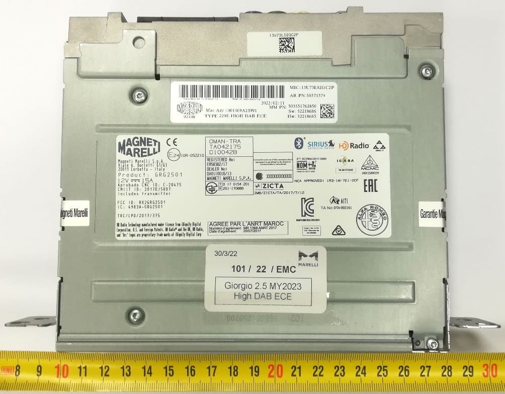
RX2GRG2501MY23
Jan 08, 2023Giorgio 2.5
Equipment Class
DSS - Part 15 Spread Spectrum Transmitter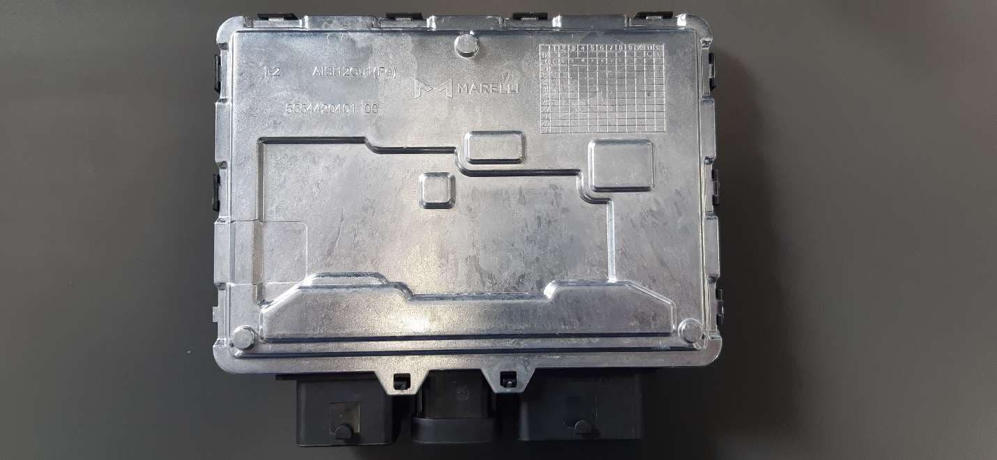
RX2BHD21
Apr 18, 2021Body Coputer Module
Equipment Class
DCD - Part 15 Low Power Transmitter Below 1705 kHz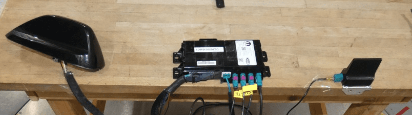
RX2TBTBMF30B0
Dec 21, 2020Telematic Control Unit
Equipment Class
DTS - Digital Transmission System