RX2NBCAI012Vehicle immobilizer
Marelli Europe S.p.A.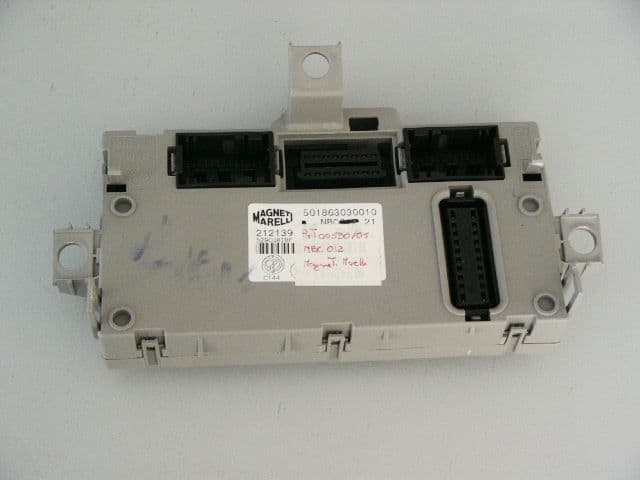
Click to zoom
Application Details
- Equipment Class
- DCD - Part 15 Low Power Transmitter Below 1705 kHz
- Date of Grant
- Oct 17, 2006
- Application Purpose
- Original Equipment
- Date of Application
- Oct 17, 2006
- Equipment Note
- Vehicle immobilizer
- Frequency Range
- 0.12500000 - 0.12500000
- Company
- Marelli Europe S.p.A.
- Country
- Italy
Documents & Files
Document Text
Text extracted from the exhibit documents filed with the FCC. Open a document above to read the original.
Users Manual
User Manual Statement Letter Federal Communications Commission 7435 Oakland Mills Road Columbia, MD 21046 Ref.: FCC ID: RX2NBCAI012 Radio equipment authorization by FCC in USA for Vehicle immobilizer NBCAI012 Dear Sirs The vehicle immobilizer will be supplied as an original equipment device to the car manufacturer. According to 47 CFR 15.19 (Labeling requirements) the car manufacturer will print the following text in the appropriate User Manuel of the car: This device complies with part 15 of the FCC Rules. Operation is subject to the following two conditions: (1) This device may not cause harmful interference and (2) this device must accept any interference received, including interference that may cause undesired operation. Changes or modifications to this unit not expressly approved by the party responsible for compliance could void the user’s authority to operate the equipment. Sincerely, ............................ Giuseppe Bergamaschi Director of Quality Department
Block Diagram
433.92 MHz SAW Filter Receiver U3741B X3 6.764375 MHz Transceiver PCF7991 X1 4.00 MHz Immobilizer Coil 125 kHz IN_RXUHF POLL_UP SER_IMMO_DATA SER_IMMO_CMD SER_IMMO_CLK Input Buffers Serial Interface Output Latches Command & Driver Relays Microprocessor X2 4.00 MHz
Cover Letter(s)
Federal Communications Commission 7435 Oakland Mills Road Columbia, MD 21046 Gentlemen: This letter is to comply with Section 0.457(d)(2)(i) pertaining to confidential material. Magneti Marelli Sistemi Elettronici S.p.A. would like the following documents regarding this submission for FCC ID: RX2NBCAI012 to be kept confidential. 1. Pages 1 to 14 of document 541863101011 – Schematic Diagram The above material contains trade secrets or technical data, which would customarily be guarded from competitors. We do not want these documents to be accessible to the general public. Sincerely, ............................ Giuseppe Bergamaschi Director of Quality Department
External Photos
External photo no. 1 External photo no. 2
ID Label/Location Info
LABEL HERE
Internal Photos
Internal photo no. 1 Internal photo no. 2
Operational Description
Magneti Marelli Sistemi Elettronici S.p.A. Direzione e Stabilimento: Centro Ricerca e Sviluppo Sede Legale: Viale Aldo Borletti, 61/63 Viale Carlo Emanuele II, 118 Viale Aldo Borletti, 61/63- 20011 Corbetta (Milano) 20011 Corbetta (Milano) 10078 Venaria Reale (Torino) Cap. Soc. Euro 74.897.548 Tel. 02 972 27 111 Tel. 011 68 79 111 Reg. Imp. Milano n. 08122270013 Fax 02 972 27 862 Fax 011 68 79 126 Rep. Econ. Amm. Milano n 1657775 Cod. Fisc. e Part. IVA 08122270013 Document N°: 01/2006 Product description and Technical specification Type NBC AI 012 Alarm system with immobilizer for FERRARI as NBC AI 012.21 MASERATI as NBC AI 013.21 Abstract This document summaries the technical characteristics of device providing information of both a specific and general nature. Ref. Doc. MMSE_TCF NBC AI 012_2006/06 sheet no. 2 of 16 Issue on date 2006-06-15 TABLE OF CONTENTS GENERAL DESCRIPTION 1.1 BLOCK DIAGRAM PIN DESCRIPTION GENERALTY BRIEF DESCRIPTION ALARM FUNCTION 2.1 DEACTIVATED 2.2 SLEEP 2.2.1 Volumetric Exclusion 2.2.2 Anti-Lifting Exclusion 2.3 INSERTION 2.3.1 Auto-Insertion 2.3.2 Reinsertion 2.4 SURVEILLANCE 2.4.1 Control of +15 signal 2.4.2 Exclusion of the External Modules far Vehicle Battery Low Tension 2.4.3 Perimetral Surveillance 2.4.4 Boot's Unlocking by the remote 2.5. ALARM 2.6. DISCONNECTION 2.7. GENERAL SPECIFICATIONS Ref. Doc. MMSE_TCF NBC AI 012_2006/06 sheet no. 3 of 16 Issue on date 2006-06-15 1.1 BLOCK DIAGRAMM LN1 LN11 LN16 LN26 LN36 AV24 M I C R O P R O C E S S O R POWER SUPPLY SIRENA SERIAL DRIVED LED DRIVER CAN PLAFON LED Input stato porta ant sx Input stato porta ant dx Input stato porta post sx Input stato porta post dx Input stato switch baule Input stato switch cofano PD14 AV25 AV 8 AV27 1 GENERAL DESCRIPTION IMMOBILIZER AV 7 AV26 Ref. Doc. MMSE_TCF NBC AI 012_2006/06 sheet no. 4 of 16 Issue on date 2006-06-15 1.2 PIN DESCRIPTION Pin Idendification Pin name Function AV 25 LN 7 Ser_siren Serial line to central unit siren LN 1 In_pa-mig Left front door input LN 11 In_pa-mip Right front door input LN 16 In_pa-psx Left rear door input LN 26 In_pa-pdx Right rear door input LN 36 In_baule Boot switch-state input AV 24 In_cofano Bonnet switch-state input PD 14 Led Output alarm led AV 26 AV 27 CAN A CAN B Line CAN slow speed AV 7 AV 8 Antenna Immobilizer Immobilizer antenna signal Hi/Low Ref. Doc. MMSE_TCF NBC AI 012_2006/06 sheet no. 5 of 16 Issue on date 2006-06-15 1.3 GENERALITY The aim of the device is to prevent intrusions and thefts to the vehicle. To do this, the device monitor and drive the following signals: DIRECT INPUT: negative signal from the switch front door driving side opened (NA) negative signal from the front door passenger side opened (NA) negative signal from the switch rear left door opened (NA) negative signal from the switch rear right door opened (NA) negative signal from the switch, boot opened (NA) negative signal from the switch bonnet opened (N C) state of the +15 signal serial line with external US and anti-lifting . DIRECT OUTPUT: Serial line with external siren Serial line with external US and anti-lifting module command of direction indicator right front command of direction indicator left front command of direction indicator right rear command of direction indicator left rear command of direction indicator right side command of direction indicator left side command of the internal curtsey light command of the LED (deterrence light) A-bus serial line command of central door locking The main componets of the device are: NBC AI 012 (Body computer) (variant of the project based on NBC 194.2X wiring diagrams) Stand-alone siren Ultrasonic sensors Anti-lifting sensor Radio control: Ferrari by customer project and Maserati by MMSE code TRF 841 Transponder of vehicles : Key SOKYMAT 942020 Immobiliser : MMSE project IMM 100.01 Ref. Doc. MMSE_TCF NBC AI 012_2006/06 sheet no. 6 of 16 Issue on date 2006-06-15 BRIEF DESCRIPTION The alarm system is able to monitor the perimetric inputs, volumetric and inclination sensors, wires disconnection and the state of the ignition key. If the alarm system detects an intrusion's attempt, it emits an optical alarm (blinking with direction indicators) and an acoustic alarm (with siren). The activation of the alarm system is indicated by the direction indicators ("on" far about 2,5s). The system commands to lock the doors and the boot compartment. During the insertion procedure it is possible to exclude the volumetric and the anti-lifting protection far the following surveillance. It is automatically re-activated during the next activation of the alarm system. Surveillance state is indicated by the LED in the passenger compartment. The LED indicates al so possible intrusions occurred during the surveillance, indicating the sensor which has detected the intrusion. Furthermore it indicates the transmitters battery state. The disconnection of the alarm system is indicated by a double flash of direction indicators. The system commands to unlock of the doors and boot compartment. In emergency cases the alarm system can be deactivated by inserting the key recognised by the immobilizer. ALARM FUNCTION The alarm systems can work in the following states deactivated state sleep state insertion state surveillance state alarm state disconnection state Please find enclosed a description for each state. DEACTIVATED The deactivated state is the state of the NBC in case of recognition of a qualified key by the immobiliser. This operation realise the disconnection of the alarm. During the deactivated state the alarm system doesn't recognise receiver commands You can pass from the deactivated state to the sleep state turning the ignition-key in KEY-OFF. SLEEP The sleep state is the basic state of the alarm system. You can pass from this state to the following ones: Surveillance: Deactivated Ref. Doc. MMSE_TCF NBC AI 012_2006/06 sheet no. 7 of 16 Issue on date 2006-06-15 when, by an insertion order (passing trough the insertion state), you …
Text truncated - open the document above for the full version.
Test Report
Senton GmbH Aeussere Fruehlingstrasse 45 D-94315 Straubing Note: The test data of this report is related only to the individual item which has been tested. This report shall not be reproduced except in full extent without the written approval of the testing laboratory. Test Report No. 55145-060179-2 (Edition 1) Page 1 of 33 Pages Straubing, 27 March 2006 T E S T - R E P O R T No. 55145-060179-2 (Edition 1) for NBC012 Transmitter for Immobilizer Applicant: T‹V PFALZ PALATINA S.u.r.l. Test Specifications: FCC Code of Federal Regulations, CFR 47, Part 15, Sections 15.205, 15.207 and 15.209 Senton GmbH Aeussere Fruehlingstrasse 45 D-94315 Straubing Test Report No. 55145-060179-2 (Edition 1) Page 2 of 33 Pages Table of Contents 1 Description of the Equipment Under Test (EUT) ........................................................ 3 2 Administrative Data..................................................................................................... 4 3 Identification of the Test Laboratory ........................................................................... 5 4 Summary .................................................................................................................... 6 5 Operation Mode and Configuration of EUT................................................................. 7 6 Measurement Procedures........................................................................................... 8 6.1 Bandwidth Measurements .................................................................................... 8 6.2 Pulse Train Measurement .................................................................................... 9 6.3 Radiated Emission Measurement 9 kHz to 30 MHz ........................................... 10 6.4 Radiated Emission in Fully or Semi Anechoic Room.......................................... 12 6.5 Radiated Emission at Open Field Test Site........................................................ 14 7 Photographs Taken During Testing .......................................................................... 15 8 Test Results .............................................................................................................. 20 8.1 Occupied Bandwidth........................................................................................... 21 8.2 Bandwidth of the Emission ................................................................................. 24 8.3 Designation of Emissions ................................................................................... 26 8.4 Pulse Train Measurement .................................................................................. 27 8.5 Restricted Bands of Operation ........................................................................... 29 8.6 Radiated Emission Measurement 9 kHz to 30 MHz .......................................... 30 8.7 Radiated Emission Measurement 30 MHz to 1 GHz ......................................... 31 9 Referenced Regulations ........................................................................................... 32 10 Charts taken during testing ....................................................................................... 34 Senton GmbH Aeussere Fruehlingstrasse 45 D-94315 Straubing Test Report No. 55145-060179-2 (Edition 1) Page 3 of 33 Pages 1 Description of the Equipment Under Test (EUT) General data of EUT Type designation 1 : NBC012 Parts 2 : 2 Serial number(s): --- Manufacturer: T‹V PFALZ PALATINA S.u.r.l. Type of equipment: Transmitter for Immobilizer Version: As received FCC ID: Additional parts/accessories: Technical data of EUT Application frequency range: 119 - 135 kHz Frequency range: 119 - 135 kHz Operating frequency: 125 kHz Type of modulation: ASK Pulse train: 1 s Pulse width: --- Number of RF-channels: 1 Channel spacing: N/A Designation of emissions 3 : 10K0A1D Type of antenna: Loop coil Size/length of antenna: 45 mm Connection of antenna: detachable not detachable Type of power supply: Battery supply Specifications for power supply: nominal voltage: 12 V 1 Type designation of the system if EUT consists of more than one part. 2 Type designations of the parts of the system, if applicable. 3 Also known as "Class of Emission". Senton GmbH Aeussere Fruehlingstrasse 45 D-94315 Straubing Test Report No. 55145-060179-2 (Edition 1) Page 4 of 33 Pages 2 Administrative Data Application details Applicant (full address): T‹V PFALZ PALATINA S.u.r.l. Via Gavardina, 7 I-25010 Ponte S. Marco (BS) Contact person: Mr. Scartapacchio Nicola Contract identification: Receipt of EUT: 3 March 2006 Date(s) of test: March 2006 Note(s): --- Report details Report number: 55145-060179-2 Edition: 1 Issue date: 27 March 2006 Senton GmbH Aeussere Fruehlingstrasse 45 D-94315 Straubing Test Report No. 55145-060179-2 (Edition 1) Page 5 of 33 Pages 3 Identification of the Test Laboratory Details of the Test Laboratory Company name: Senton GmbH EMI/EMC Test Center Address: Aeussere Fruehlingstrasse 45 D-94315 Straubing Germany Laboratory accreditation: DAR-Registration No. DAT-P-171/94-02 FCC test site registration number 90926 Industry Canada test site registration: IC 3050 Contact person: Mr. Johann Roidt Phone: (+49) (0)9421 5522-0 Fax: (+49) (0)9421 5522-99 Senton GmbH Aeussere Fruehlingstrasse 45 D-94315 Straubing Test Report No. 55145-060179-2 (Edition 1) Page 6 of 33 Pages 4 Summary Summary of test results The tested sample complies with the requirements set forth in the Code of Federal Regulations CFR 47, Part 15, Sections 15.205 and 15.209 of the Federal Communication Commission (FCC). Personnel involved in this report Laboratory Manager: Mr. Johann Roidt Responsible for testing: Mr. Martin Steindl Responsible for test report: Mr. Martin Steindl Senton GmbH Aeussere Fruehlingstrasse 45 D-94315 Straubing Test Report No. 55145-060179-2 (Edition 1) Page 7 of 33 Pages 5 Operation Mode and Configuration of EUT Operation Mode All radiated emissions were measured with unm…
Text truncated - open the document above for the full version.
Test Setup Photos
Test Setup photo no. 1 Test Setup photo no. 2 Test Setup photo no. 3 Test Setup photo no. 4 Test Setup photo no. 5 Test Setup photo no. 6 Test Setup photo no. 7 Test Setup photo no. 8 Test Setup photo no. 9
Contact Information
Applicant
Andrea Gozzo(Mr.)
Test Firm
TUV SUD Product Service GmbH PS-EMC-STRRainer Heller
Technical Specifications
| # | Rule Parts | Frequency Range | Power Output |
|---|---|---|---|
| 1 | 15C | 0.125 MHz - 0.125 MHz | - |
Other Applications from Marelli Europe S.p.A.
RX2HUAIDP21BY
Aug 11, 2024Infotainment Head Unit
Equipment Class
NII - Unlicensed National Information Infrastructure TXRX2HUAIDP20BY
Apr 10, 2024Infotainment Head Unit
Equipment Class
NII - Unlicensed National Information Infrastructure TX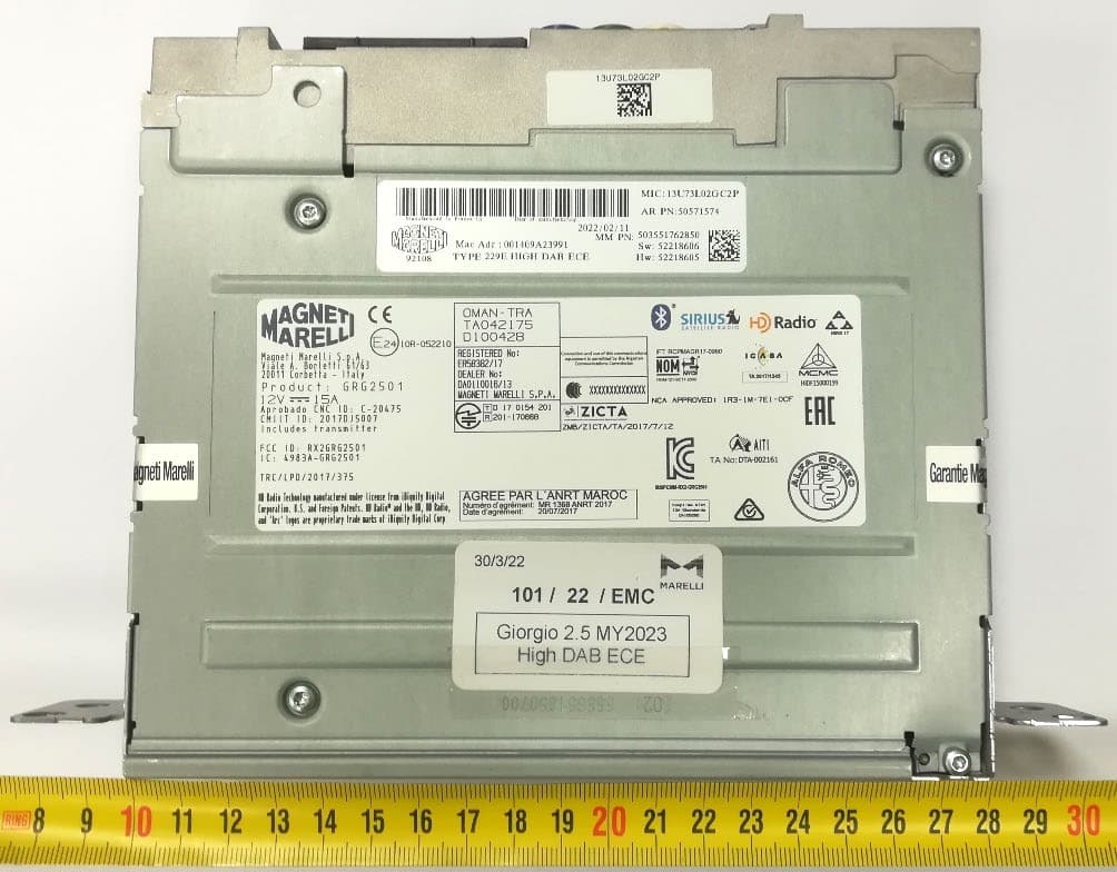
RX2GRG2501MY23
Jan 08, 2023Giorgio 2.5
Equipment Class
DSS - Part 15 Spread Spectrum Transmitter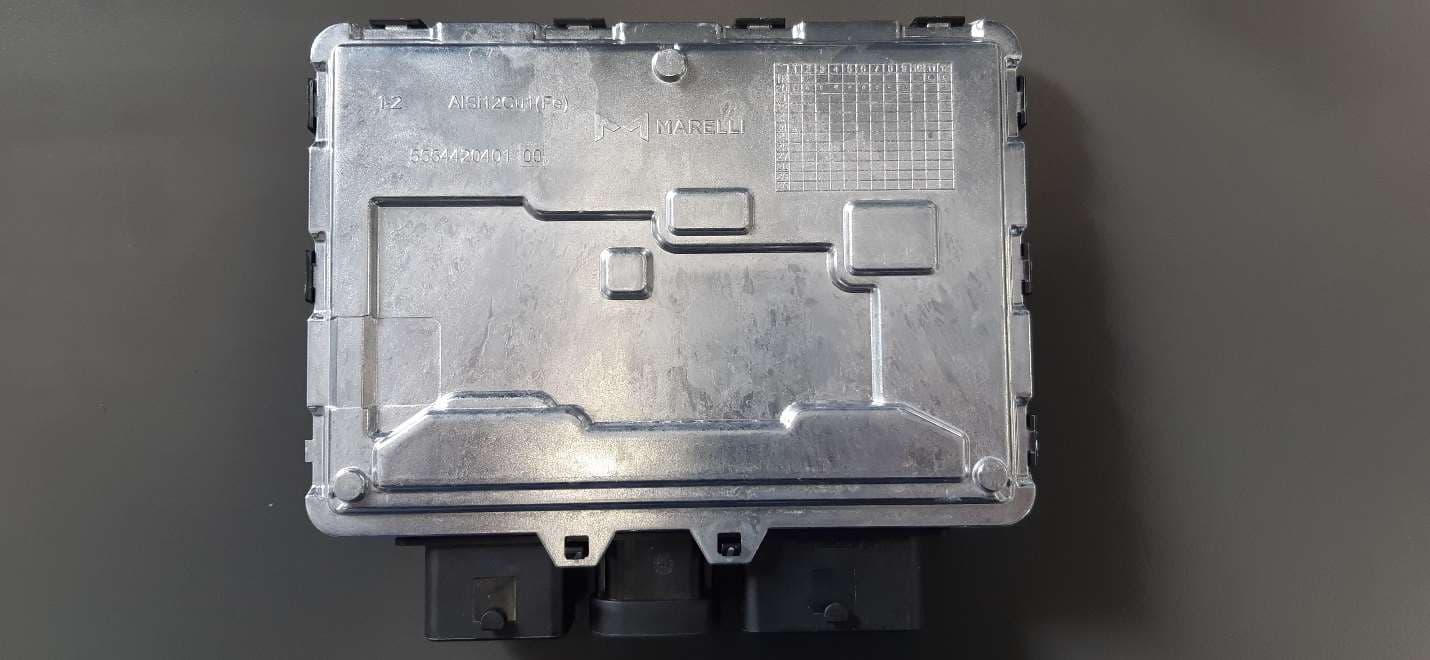
RX2BHD21
Apr 18, 2021Body Coputer Module
Equipment Class
DCD - Part 15 Low Power Transmitter Below 1705 kHz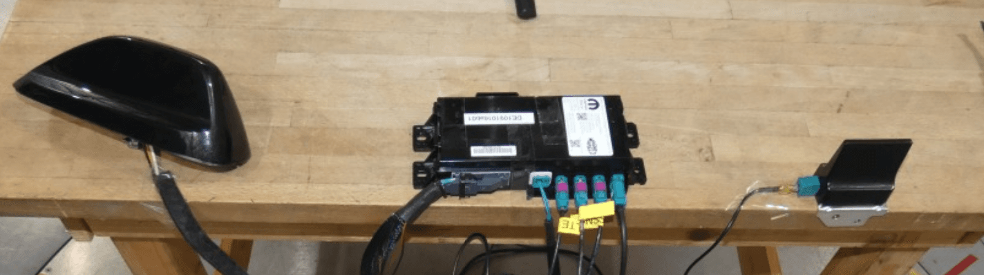
RX2TBTBMF30B0
Dec 21, 2020Telematic Control Unit
Equipment Class
DTS - Digital Transmission System