RX2TRF937Remote Control Key Transmitter
Marelli Europe S.p.A.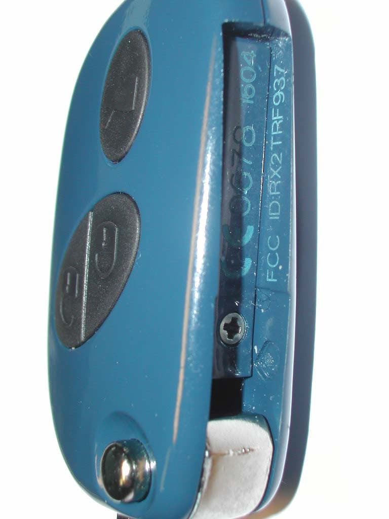
Click to zoom
Application Details
- Equipment Class
- DSC - Part 15 Security/Remote Control Transmitter
- Date of Grant
- Feb 01, 2005
- Application Purpose
- Original Equipment
- Date of Application
- Feb 01, 2005
- Equipment Note
- Remote Control Key Transmitter
- Frequency Range
- 433.92000000 - 433.92000000
- Company
- Marelli Europe S.p.A.
- Country
- Italy
Documents & Files
Document Text
Text extracted from the exhibit documents filed with the FCC. Open a document above to read the original.
Users Manual
User Manual Statement Letter Federal Communications Commission 7435 Oakland Mills Road Columbia, MD 21046 Ref.: FCC ID: RX2TRF937 Radio equipment authorization by FCC in USA for Remote control key transmitter TRF937 Dear Sirs The remote control key transmitter will be supplied as an original equipment device to the car manufacturer. According to 47 CFR 15.19 (Labelling requirements) the car manufacturer will print the following text in the appropriate User Manuel of the car: This device complies with part 15 of the FCC Rules. Operation is subject to the following two conditions: (1) This device may not cause harmful interference and (2) this device must accept any interference received, including interference that may cause undesired operation. Changes or modifications to this unit not expressly approved by the party responsible for compliance could void the user’s authority to operate the equipment. Sincerely, Magneti Marelli Sistemi Elettronici S.p.A.
Block Diagram
Sistemi Elettronici Viale Aldo BORLETTI 61/63 I-20011CORBETTA - MI Tel +39-02.9722.1 Block Diagram
Operational Description
Sistemi Elettronici Viale Aldo BORLETTI 61/63 I-20011CORBETTA - MI Tel +39-02.9722.1 Document No.: 09/2004 Page 1/6 Version 01 Date: 04-09-20 Product description and Technical specification Type TRF 937/010 Radio control Abstract This document summaries the technical characteristics of the RF RADIO CONTROL device providing information of both a specific and a general nature. Sistemi Elettronici Viale Aldo BORLETTI 61/63 I-20011CORBETTA - MI Tel +39-02.9722.1 Document No.: 09/2004 Page 2/6 Version 01 Date: 04-09-20 INTRODUCTION Aim Provide a description of the product RADIO CONTROL TRF 937/010 for use with FIAT AUTO 139 along with technical information and instructions for a correct use of the product. Glossary Indicate: - RX receiver placed inside the NBC board (radiofrequency 433.92 MHz) - F 0 working frequency (433.92 MHz) - V B battery voltage - T AMB room temperature Sistemi Elettronici Viale Aldo BORLETTI 61/63 I-20011CORBETTA - MI Tel +39-02.9722.1 Document No.: 09/2004 Page 3/6 Version 01 Date: 04-09-20 GENERAL DESCRIPTION Generality The component RADIO CONTROL TRF 937/010 in “key head” consists of the following parts: N°1 base plate N°2 plastic semi-shell (key body) N°1 lithium battery CR 2032 (3V 180 mAh) The information provided in this document relates to the RADIO CONTROL RF. For the remaining subjects (Overhead receiver RF) refer to the specific product description. The purpose of the device is to carry out the functions of TRANSMISSION of the encrypted variable code to the RF receiver placed in the NBC 139 and the SIGNALLING of the level of the batteries that supply it. The transmission of the code allows (using the dedicated switches) insertion and disconnection of the alarm system, locking and unlocking of central door locking and opening of boot compartment. Sistemi Elettronici Viale Aldo BORLETTI 61/63 I-20011CORBETTA - MI Tel +39-02.9722.1 Document No.: 09/2004 Page 4/6 Version 01 Date: 04-09-20 Block diagram List of functions The purpose of the device is to carry out the following functions: Transmission of a variable code to the receiver RRF 010 This is carried out through a transistor oscillator stabilised with a SAW Resonator (f 0 =433.92 MHz), the antenna’s type is of a “spiral” screen, printed directly onto the circuit; the “encrypted” variable code is sent, modulating in amplitude the carrier generated by the oscillator (ASK-digital amplitude modulator-) through a dedicated integrated circuit. Sistemi Elettronici Viale Aldo BORLETTI 61/63 I-20011CORBETTA - MI Tel +39-02.9722.1 Document No.: 09/2004 Page 5/6 Version 01 Date: 04-09-20 Signalling of the level of the lithium battery A gauge with fixed threshold has been placed inside the dedicated integrated circuit and it enables us to distinguish OK batteries from wasted ones, through two different means of led piloting. By pressing the button it generates: - OK batteries => flashing led for the entire duration of the pressure on the key - Wasted battery => just 1 flash of the led on pressing the key After a hundred transmissions with low level battery supply voltage, the system cuts off the function of the remote control. It restarts itself only if a new full charge battery replaces the wasted one, otherwise the remote control doesn’t restart itself (saved in EEPROM). The logic stage exists of: - dedicated, integrated circuit - three normally opened pushbutton - led The function of this H/W stage is the generation of the variable code (by modulating the oscillator). Keys’ functions The remote control has three keys respectively called BLOCK, UNBLOCKING and BOOT. The keys operate the following functions: BLOCK Pressing the BLOCK keys the doors will lock and insert the eventual alarm system. Pressing more then 4 seconds the windows and the sliding roof will close automatically (SUPERLOCKING). The movement will interrupt itself if the key’s pressure stop. New pressure for 4 seconds will start the function again. UNBLOCKING Pressure of the unlocking key will unlock the doors, switch the inside lights and disconnect the eventual alarm system (SUPERUNLOCKING). Pressing the key for more then 4 seconds the windows and the sliding-roof will open automatically. BOOT Pressing the key will unlock the boot/rear door, visible from the slight lifting of this one. It will partially disconnect also the eventual alarm system. Sistemi Elettronici Viale Aldo BORLETTI 61/63 I-20011CORBETTA - MI Tel +39-02.9722.1 Document No.: 09/2004 Page 6/6 Version 01 Date: 04-09-20 Electronic specifications Clock frequency : 13,56 MHz Power supply : 3 volts (battery) Absorption (RUN mode) : <1.5 mA (B) max 100 μA (Standby mode) max 100 nA Logic levels for inputs “0” max : 0,45V “1” min : 1,65V Logic levels for outputs “1” min : 2,4V “0” max : 0,24V Threshold for the signalling of flat batteries : 2.0V<V B <2.4V Note: (B) @V B = 3V; T AMB = 25°C Power supply This is made up of 1 lithium battery (Li/MnO 2 button cell), 3V nominal voltage. Nominal voltage : 3V Standard capacity : 180 mAh (A) Discharge current (continuative) : 3 mA (impulsive) : 10 mA Temperature range : -20°C÷+65°C Note: (A) from 3V to 2V; 15 kΩ load; T AMB = 25°C
Test Report
EMV-Pr ̧fzentrum EMI/EMC-Testcenter FCC-ID: Test Report No.: 55145-40286 Page 1 of 20 Pages Straubing, 02 June 2004 T E S T - R E P O R T No. 55145-40286 for TRF 010 Remote Control Transmitter Applicant: T‹V Pfalz Palatina S.u.r.l. Test Specification: FCC Code of Federal Regulations, Part 15 Subpart C, Section 15.231 Note: The test data of this report relate only to the individual item which has been tested. This report shall not be reproduced except in full extent without the written approval of the testing laboratory. EMV-Pr ̧fzentrum EMI/EMC-Testcenter FCC-ID: Test Report No.: 55145-40286 Page 2 of 20 Pages Table of Contents 1. Administrative Data.....................................................................................3 2. Identification of Test Laboratory .................................................................4 3. Operation Mode of EUT..............................................................................5 4. Configuration ..............................................................................................6 5. Measuring Methods ....................................................................................7 5.1. Field Strength of Emissions, Prescans in a fully-anechoic room (30 MHz ñ 1 GHz) .......................................................................8 5.2. Fieldstrength of Emissions, Measurement at Open Area Test Site (30 MHz ñ 1 GHz) .................................................................9 5.3. Fieldstrength of Emissions above 1 GHz ...........................................10 6. Photographs Taken During Testing ..........................................................11 7. List of Measurements ...............................................................................14 8. Referenced Regulations ...........................................................................19 Charts taken during testing ...............................................................................20 EMV-Pr ̧fzentrum EMI/EMC-Testcenter FCC-ID: Test Report No.: 55145-40286 Page 3 of 20 Pages 1. Administrative Data Test item (EUT) Type designation TRF 010 Serial number(s): 001 Type of equipment: Remote Control Transmitter Parts/accessories: FCC-ID: Technical data Frequency range N/A Operational frequency 433.92 MHz Type of modulation 19K6A1D Pulse frequency N/A Pulse width N/A Antenna Integrated Power supply 3 V lithium battery Applicant: (full address) T‹V Pfalz Palatina S.u.r.l. Via Gavardina, 7 I-25010 Ponte S. Marco (BS) Contract identification: --- Contact person: N. Scartapacchio Manufacturer: T‹V Pfalz Palatina S.u.r.l. Application details Receipt of EUT: 20 April 2004 Date of test: April - May 2004 Note: Responsible for testing: Martin Steindl Responsible for test report: Martin Steindl EMV-Pr ̧fzentrum EMI/EMC-Testcenter FCC-ID: Test Report No.: 55145-40286 Page 4 of 20 Pages 2. Identification of Test Laboratory DETAILS OF THE TEST LABORATORY COMPANY NAME: Senton GmbH EMI/EMC Test Center ADDRESS: Aeussere Fruehlingsstrasse 45 D-94315 Straubing Germany LABORATORY ACCREDITATION: DAR-Registration No. TTI-P-G 062/94-01 FCC TEST SITE LISTING 90926 INDUSTRY CANADA TEST SITE REGISTRATION IC 3050 NAME FOR CONTACT PURPOSES: Mr. Johann Roidt TELEPHONE: (+49) (0)9421 5522-0 FAX: (+49) (0)9421 5522-99 PERSONNEL INVOLVED IN THIS TEST REPORT LABORATORY MANAGER: Mr. Johann Roidt RESPONSIBLE FOR TESTING: Mr. Martin Steindl RESPONSIBLE FOR TEST REPORT: Mr. Martin Steindl SUMMARY OF TEST RESULTS The tested sample complies with the requirements set forth in the FCC Code of Federal Regulations Part 15, Subpart C, Section 15.231 EMV-Pr ̧fzentrum EMI/EMC-Testcenter FCC-ID: Test Report No.: 55145-40286 Page 5 of 20 Pages 3. Operation Mode of EUT While one button is pressed, the transmitter continuously sends the corresponding datagram. When the button is released, the transmitter stops working instantly. EMV-Pr ̧fzentrum EMI/EMC-Testcenter FCC-ID: Test Report No.: 55145-40286 Page 6 of 20 Pages 4. Configuration Configuration of the EUT Not applicable Cables connected to the EUT Not applicable Peripheral devices connected to the EUT Not applicable EMV-Pr ̧fzentrum EMI/EMC-Testcenter FCC-ID: Test Report No.: 55145-40286 Page 7 of 20 Pages 5. Measuring Methods EMV-Pr ̧fzentrum EMI/EMC-Testcenter FCC-ID: Test Report No.: 55145-40286 Page 8 of 20 Pages 5.1. Field Strength of Emissions, Prescans in a fully-anechoic room (30 MHz ñ 1 GHz) Rules and Specifications: Sections 15.109 & 15.231 Guide: ANSI C63.4 1997 Measurement Procedure: Radiated emissions are measured over the frequency range from 30 MHz to 1 GHz. Measurements were made in both the horizontal and vertical planes of polarization in a fully anechoic room using a spectrum analyzer with the detector function set to peak and resolution bandwidth set to 100 kHz. All tests were performed at a test-distance of 3 meters. Hand-held or body-worn devices are rotated through three orthogonal axes to determine which attitude and configuration produces the highest emission relative to the limit and therefore shall be used for final testing. EUT Fully anechoic chamber 3 m test distance Spectrum Analyzer Test instruments used: No. Type Model Serial Number Manufacturer 01 Spectrum Analyzer FSP 30 100063 Rohde & Schwarz 113 Preamplifier CPA9231A 3393 Schaffner 141 Biconical antenna HK 116 829708/006 Rohde & Schwarz 143 Log. periodic antenna 3147 9112-1054 EMCO 003 Fully anechoic room No. 2 1452 Albatross Projects EMV-Pr ̧fzentrum EMI/EMC-Testcenter FCC-ID: Test Report No.: 55145-40286 Page 9 of 20 Pages 5.2. Fieldstrength of Emissions, Measurement at Open Area Test Site (30 MHz ñ 1 GHz) Rules and Specifications: Sections 15.109 & 15.231 Guide: ANSI C63.4 1997 Measurement Procedure: Measurement Procedure: For final testing an open-area test-side was used. Radiated emissions are measured over the frequency range from 30 MHz to 1 GHz. Measurements were made in both the horizontal and vertical planes of polarisatio…
Text truncated - open the document above for the full version.
Test Setup Photos
EMV-Pr ̧fzentrum EMI/EMC-Testcenter FCC-ID: Test Report No.: 55145-40286 Page 12 of 20 Pages Test setup for radiated emission measurement (fully anechoic room) EMV-Pr ̧fzentrum EMI/EMC-Testcenter FCC-ID: Test Report No.: 55145-40286 Page 13 of 20 Pages Test setup for radiated emission measurement (open-area test-side)
Contact Information
Applicant
Andrea Gozzo(Mr.)
Test Firm
TUV SUD Product Service GmbH PS-EMC-STRRainer Heller
Technical Specifications
| # | Rule Parts | Frequency Range | Power Output |
|---|---|---|---|
| 1 | 15.231 | 433.92 MHz - 433.92 MHz | - |
Other Applications from Marelli Europe S.p.A.
RX2HUAIDP21BY
Aug 11, 2024Infotainment Head Unit
Equipment Class
NII - Unlicensed National Information Infrastructure TXRX2HUAIDP20BY
Apr 10, 2024Infotainment Head Unit
Equipment Class
NII - Unlicensed National Information Infrastructure TX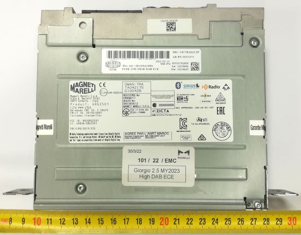
RX2GRG2501MY23
Jan 08, 2023Giorgio 2.5
Equipment Class
DSS - Part 15 Spread Spectrum Transmitter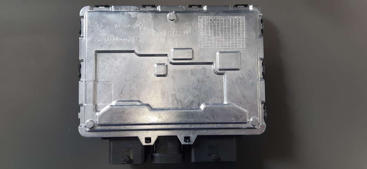
RX2BHD21
Apr 18, 2021Body Coputer Module
Equipment Class
DCD - Part 15 Low Power Transmitter Below 1705 kHz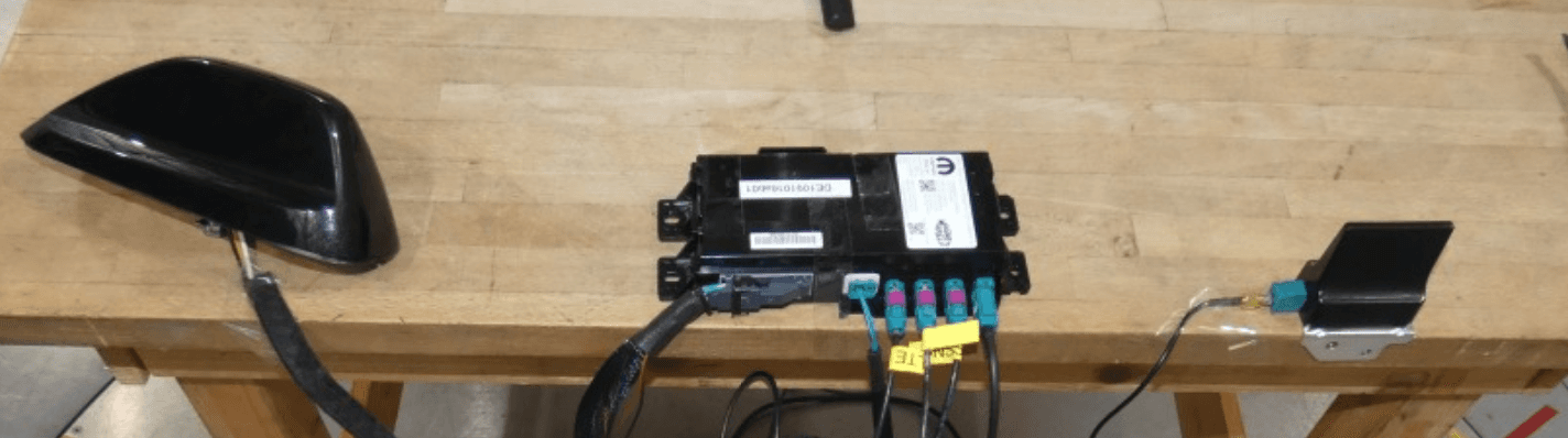
RX2TBTBMF30B0
Dec 21, 2020Telematic Control Unit
Equipment Class
DTS - Digital Transmission System