RXB-TIRUWireless Data Monitor
Tempris GmbH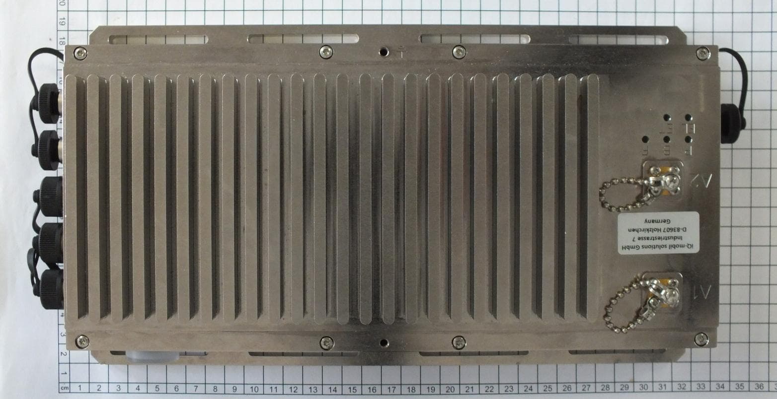
Click to zoom
Application Details
- Equipment Class
- DTS - Digital Transmission System
- Date of Grant
- Mar 04, 2013
- Application Purpose
- Original Equipment
- Date of Application
- Mar 04, 2013
- Equipment Note
- Wireless Data Monitor
- Frequency Range
- 2441.00000000 - 2441.00000000
- Company
- Tempris GmbH
- Country
- Germany
Documents & Files
Document Text
Text extracted from the exhibit documents filed with the FCC. Open a document above to read the original.
Users Manual
TEMPRIS User Manual TEMPRIS LAB and TEMPRIS PRO Temperature Measurement Systems TEMPRIS DataServer Version 7.0 User Guide TEMPRIS User Manual Publication Notes Page 3 of 80 TEMPRIS User Manual TEMPRIS LAB and TEMPRIS PRO Temperature Measurement Systems TEMPRIS DataServer Version 7.0 User Guide Document Version: 7.0.009 Last printing: October 2012 Published by: iQ-mobil solutions GmbH, Holzkirchen, Germany The information contained in this documentation as well as the products and/or programs described therein are subject to change without notice and should not be construed as a commitment by iQ-mobil solutions GmbH. Although iQ-mobil have gone to great effort to verify the integrity of the information provided with the TEMPRIS documentation, this documentation could contain technical inaccuracies or typographical errors. iQ-mobil shall not be liable for errors contained therein or for incidental consequential damages in connection with the furnishing, performance or use of this material. iQ-mobil appreciate readers' and/or users' comments in order to improve this documentation and/or the products described therein. Changes are periodically made to the information therein. These changes will be incorporated in new editions of the TEMPRIS documentation. All rights reserved. No part of the TEMPRIS documentation may be reproduced, stored in a retrieval system, translated, transcribed or transmitted, in any form or by any means manual, electric, electronic, electromagnetic, mechanical, chemical, optical or otherwise without prior express written permission from iQ-mobil solutions GmbH. TEMPRIS® is a registered trademark of iQ-mobil solutions GmbH. TEMPRIS DataServer™ is a trademark of iQ-mobil solutions GmbH. All other products or services mentioned in this publication are identified by the trademarks or service marks of their respective companies or organizations. Copyright © 2009-2012 iQ-mobil solutions GmbH. All Rights Reserved. TEMPRIS User Manual Contents Page 4 of 80 Contents 1 Important Information ................................................................................. 7 1.1 Using this Documentation ..................................................................................... 7 Compilation and Publication Notice ......................................................................... 7 Organization of this Documentation ........................................................................ 7 Illustrations ......................................................................................................... 8 Copyright ............................................................................................................ 8 Trademarks ......................................................................................................... 8 1.2 Symbols and Conventions ..................................................................................... 9 Terms and Notations ............................................................................................ 9 Acronyms ............................................................................................................ 9 Symbolic Conventions.......................................................................................... 10 Safety Symbols ................................................................................................... 11 1.3 Intended Use ...................................................................................................... 12 1.4 Operators and Users ............................................................................................ 12 1.5 Operator Obligations ........................................................................................... 12 1.6 User Obligations ................................................................................................. 12 1.7 Safety Instructions .............................................................................................. 13 1.7.1 Important Safety Instructions .................................................................... 13 1.7.2 CE Compliance ......................................................................................... 15 1.7.3 United States FCC Compliance ................................................................... 16 1.7.4 Industry Canada (IC) Compliance .............................................................. 17 1.8 Related Documentation ........................................................................................ 18 1.9 Addresses .......................................................................................................... 18 2 Introduction ............................................................................................... 19 2.1 TEMPRIS - Wireless Temperature Monitoring without Batteries ................................. 19 2.2 TEMPRIS Operational Principle .............................................................................. 20 2.3 TEMPRIS Applications .......................................................................................... 21 3 TEMPRIS System Setup .............................................................................. 23 3.1 TEMPRIS System Components .............................................................................. 23 3.2 Required Cable Connections ................................................................................. 25 3.2.1 TEMPRIS PRO Connections and Interfaces ................................................... 25 3.2.2 TEMPRIS LAB Connections and Interfaces ................................................... 28 3.3 TEMPRIS DataServer Installation .......................................................................... 31 3.3.1 TEMPRIS DataServer System Requirements ................................................ 31 3.3.2 New Installation ....................................................................................... 32 3.3.3 Upd…
Text truncated - open the document above for the full version.
External Photos
mikes-testingpartners gmbh File No. T35617-00-xxHS, page 3 of 5 Ohmstrasse 2-4 94342 STRASSKIRCHEN GERMANY Tel.: +49(0)9424-94810 Fax: +49(0)9424-9481240 Rev. No. 1.1; 9.9.2010 1 P h o t o d o c u m e n t a t i o n o f t h e E U T 1.1 External view: mikes-testingpartners gmbh File No. T35617-00-xxHS, page 4 of 5 Ohmstrasse 2-4 94342 STRASSKIRCHEN GERMANY Tel.: +49(0)9424-94810 Fax: +49(0)9424-9481240 Rev. No. 1.1; 9.9.2010 mikes-testingpartners gmbh File No. T35617-00-xxHS, page 5 of 5 Ohmstrasse 2-4 94342 STRASSKIRCHEN GERMANY Tel.: +49(0)9424-94810 Fax: +49(0)9424-9481240 Rev. No. 1.1; 9.9.2010
ID Label/Location Info
TEMPRIS LAB DC-IN U0 AUX USB DVI ETH Label 1 P. Fischer A. Bauer Label 2: Nameplate TIRU Label 4: Nameplate TLAB Label 3: Compliance E 00 Label 1: TIRU Serial number, MAC address, IP addre ss Label 6: TLAB Serial number, Order number Label 6 01 Ratings Label 4 PF 2012-01-04 12-05-25 2012-11-13 02 S/N L-Cxxx-Pyyww MAC xx-xx-xx-xx-xx-xx IP 1 : 10.10.0.100 IP 2 : 192.168.1.100 03 No: 101.210 Var.x Rev.Xxx S/N xxxx_yyyyWww 63,5 29,6 40 1 63,5 63,5 29,6 29,6 2,6 10 115 110 70 30 70 38 19 38 81 Label 2 Label 3 Label 4 Label 5 63,5 29,6 63,5 29,6 38 19 63,5 29,6 19 38 GB Copyright © 2009-2012 iQ-mobil solutions GmbH Name 7 Checked 3 Document status: Blatt/Page TLAB1101-006-00B02 Werkstoff / Material: Nam. 3 9 Aenderung/Change 6 Drawn C Weitergabe sowie Vervielfältigung dieses Dokuments, Verwertung und Mitteilung seines Inhalts sind verboten, soweit nicht ausdrücklich gestattet. Zuwiderhandlungen verpflichten zu Schadenersatz. Alle Rechte für den Fall der Patent-, Gebrauchsmuster- oder Geschmacksmustereintragung vorbehalten. 1 Titel / Title 5 1101-006-00B02&MTB90 E E 7 Oberfläche / Surface: GF 1 2 Origin: Date F 1 D The reproduction, distribution and utilization of this document as well as the communication of its contents to others without express authorization is prohibited. Offenders will be held liable for the payment of damages. All rights reserved in the event of the grant of a patent, utility model or design. 2 5 1 Maßstab / Scale Date A SHT 8 Approved File No.: Zeichnungsnummer / DWG No. 8 TLAB / TIRU Label assembly D iQ-mobil solutions GmbH C Dimension drawing 6 Dokumentenart / Document type: REV. 4 B 4 9 Gewicht /Weight Released AGB Copyright © 2009-2012 iQ-mobil solutions GmbH Name 7 Checked 3 Document status: Blatt/Page TLAB1101-006-00B02 Werkstoff / Material: Nam. 3 9 Aenderung/Change 6 Drawn C Weitergabe sowie Vervielfältigung dieses Dokuments, Verwertung und Mitteilung seines Inhalts sind verboten, soweit nicht ausdrücklich gestattet. Zuwiderhandlungen verpflichten zu Schadenersatz. Alle Rechte für den Fall der Patent-, Gebrauchsmuster- oder Geschmacksmustereintragung vorbehalten. 1 Titel / Title 5 1101-006-00B02&MTB90 E E 7 Oberfläche / Surface: GF 1 2 Origin: Date F 1 D The reproduction, distribution and utilization of this document as well as the communication of its contents to others without express authorization is prohibited. Offenders will be held liable for the payment of damages. All rights reserved in the event of the grant of a patent, utility model or design. 2 5 1 Maßstab / Scale Date A SHT 8 Approved File No.: Zeichnungsnummer / DWG No. 8 TLAB / TIRU Label assembly D iQ-mobil solutions GmbH C Dimension drawing 6 Dokumentenart / Document type: REV. 4 B 4 9 Gewicht /Weight Released A P. Fischer INIT PF U1 This device complies with Part 15 of the FCC Rules Operation is subject to the following two conditions:(1)this device may not cause harmful interference a nd (2)this device must accept any interference, includ ing interference that may cause undesired operation Label 1: Serial number TIRU, MAC address TIRU, IP a ddress TIRU Label 2: Nameplate TIRULabel 3: CompianceLabel 4: Nameplate TLABLabel 5: Microsoft Product Key Label 6: Serial number TLAB, Order number TLAB 2012-01-04 12-04-04 PF Label w. FCC-No 12-11-13 PF Label w. o. FCC-No 12-11-29
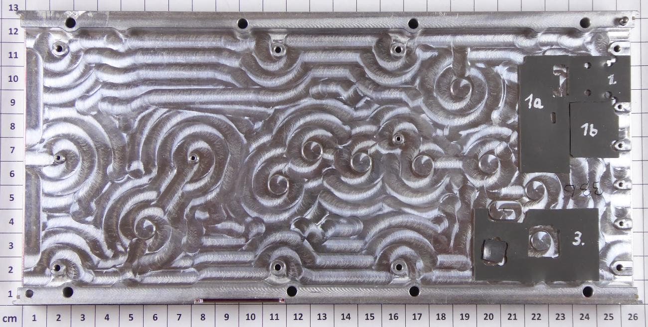
Internal Photos
mikes-testingpartners gmbh File No. T35617-00-xxHS, page 5 of 9 Ohmstrasse 2-4 94342 STRASSKIRCHEN GERMANY Tel.: +49(0)9424-94810 Fax: +49(0)9424-9481240 Rev. No. 1.1; 9.9.2010 1.2 Internal view: mikes-testingpartners gmbh File No. T35617-00-xxHS, page 6 of 9 Ohmstrasse 2-4 94342 STRASSKIRCHEN GERMANY Tel.: +49(0)9424-94810 Fax: +49(0)9424-9481240 Rev. No. 1.1; 9.9.2010 mikes-testingpartners gmbh File No. T35617-00-xxHS, page 7 of 9 Ohmstrasse 2-4 94342 STRASSKIRCHEN GERMANY Tel.: +49(0)9424-94810 Fax: +49(0)9424-9481240 Rev. No. 1.1; 9.9.2010 mikes-testingpartners gmbh File No. T35617-00-xxHS, page 8 of 9 Ohmstrasse 2-4 94342 STRASSKIRCHEN GERMANY Tel.: +49(0)9424-94810 Fax: +49(0)9424-9481240 Rev. No. 1.1; 9.9.2010 mikes-testingpartners gmbh File No. T35617-00-xxHS, page 9 of 9 Ohmstrasse 2-4 94342 STRASSKIRCHEN GERMANY Tel.: +49(0)9424-94810 Fax: +49(0)9424-9481240 Rev. No. 1.1; 9.9.2010
Test Report
FCC ID: RXB-TIRU mikes-testingpartners gmbh File No. T35617-03-00HS, page 1 of 44 Ohmstrasse 2-4 94342 STRASSKIRCHEN GERMANY Tel.:+49(0)9424-94810 Fax: ++49(0)9424-9481240 Rev. No. 1.2, 24.8.2011 EMI − T E S T R E P O R T - FCC Part 15.247 and RSS 210 - Test Report No. : T35617-03-00HS 05 March 2013 ______________________________________________________________________________________________ Date of issue Type / Model Name : TIRU Product Description : Wireless data monitor Applicant : iQ-mobil solutions GmbH Address : Industriestr. 7 83607 HOLZKIRCHEN, GERMANY Manufacturer : iQ-mobil solutions GmbH Address : Industriestr. 7 83607 HOLZKIRCHEN, GERMANY Licence holder : iQ-mobil solutions GmbH Address : Industriestr. 7 83607 HOLZKIRCHEN, GERMANY Test Result according to the standards listed in clause 1 test standards: POSITIVE The test report merely corresponds to the test sample. It is not permitted to copy extracts of these test results without the written permission of the test laboratory. FCC ID: RXB-TIRU mikes-testingpartners gmbh File No. T35617-03-00HS, page 2 of 44 Ohmstrasse 2-4 94342 STRASSKIRCHEN GERMANY Tel.:+49(0)9424-94810 Fax: ++49(0)9424-9481240 Rev. No. 1.2, 24.8.2011 Contents 1 T E S T S T A N D A R D S 3 2 S U M M A R Y 4 2.1 Test result summary 4 2.2 GENERAL REMARKS: 5 2.3 FINAL ASSESSMENT: 6 3 E Q U I P M E N T U N D E R T E S T 7 3.1 Photo documentation of the EUT – Please see attachment A 7 3.1 Power supply system utilised 7 3.2 Short description of the equipment under test (EUT) 7 4 T E S T E N V I R O N M E N T 8 4.1 Address of the test laboratory 8 4.2 Environmental conditions 8 4.3 Statement of the measurement uncertainty 8 4.4 Measurement protocol for FCC and IC 9 4.5 Determination of worst case measurement conditions 9 5 T E S T C O N D I T I O N S A N D R E S U L T S 10 5.1 Conducted emissions 10 5.2 Emission bandwidth and occupied bandwidth 14 5.3 Maximum peak conducted output power 17 5.4 Spurious emissions conducted, in non-restricted bands 19 5.5 Spurious emissions conducted, in restricted bands 28 5.1 Spurious emissions radiated, cabinet radiation 34 5.2 Power spectral density 39 5.3 Maximum permissible exposure (MPE) 41 5.4 Co-location and co-transmission 42 5.5 Antenna application 43 6 U S E D T E S T E Q U I P M E N T A N D A C C E S S O R I E S 44 Attachment A, T35617-00-xxHS FCC ID: RXB-TIRU mikes-testingpartners gmbh File No. T35617-03-00HS, page 3 of 44 Ohmstrasse 2-4 94342 STRASSKIRCHEN GERMANY Tel.:+49(0)9424-94810 Fax: ++49(0)9424-9481240 Rev. No. 1.2, 24.8.2011 1 T E S T S T A N D A R D S The tests were performed according to following standards: FCC Rules and Regulations Part 15, Subpart A - General (September, 2012) Part 15, Subpart A, Section 15.31 Measurement standards Part 15, Subpart A, Section 15.33 Frequency range of radiated measurements Part 15, Subpart A, Section 15.35 Measurement detector functions and bandwidths FCC Rules and Regulations Part 15, Subpart C - Intentional Radiators (September, 2012) Part 15, Subpart C, Section 15.203 Antenna requirement Part 15, Subpart C, Section 15.204 External radio frequency power amplifiers and antenna modifications Part 15, Subpart C, Section 15.205 Restricted bands of operation Part 15, Subpart C, Section 15.207 Conducted limits Part 15, Subpart C, Section 15.209 Radiated emission limits, general requirements Part 15, Subpart C, Section 15.247 Operation within the bands 902 - 928 MHz, 2400 - 2483.5 MHz and 5725 - 5850 MHz FCC Rules and Regulations Part 1, Subpart I - Procedures Implementing the National Environmental Policy Act of 1969 Part 1, Subpart I, Section 1.1310 Radiofrequency radiation exposure limits Part 1, Subpart 2, Section 2.1093 Radiofrequency radiation exposure evaluation: portable device OET Bulletin 65, 65A, 65B, 65C Edition 97-01, August 1997 – Evaluating Compliance with FCC Guidelines for Human Exposure to Radio Frequency Electromagnetic Fields. ANSI C63.4: 2009 Methods of Measurement of Radio-Noise Emissions from Low- Voltage Electrical and Electronic Equipment in the Range of 9 kHz to 40 GHz ANSI C63.10: 2009 Testing Unlicensed Wireless Devices ANSI C95.1: 2005 IEEE Standard for Safety Levels with respect to Human Exposure to Radio Frequency Electromagnetic Fields, 3 kHz to 300 GHz CISPR 16-4-2: 2003 Uncertainty in EMC measurement CISPR 22: 2005 Information technology equipment EN 55022: 2006 KDB 558074 D01 v02 Guidance for performing compliance measurements on DTS operating under Section 15.247, 2012-10-4. FCC ID: RXB-TIRU mikes-testingpartners gmbh File No. T35617-03-00HS, page 4 of 44 Ohmstrasse 2-4 94342 STRASSKIRCHEN GERMANY Tel.:+49(0)9424-94810 Fax: ++49(0)9424-9481240 Rev. No. 1.2, 24.8.2011 2 S U M M A R Y 2.1 Test result summary DTS device using digital modulation and operating in the frequency range 2400 MHz – 2483.5 MHz: FCC Rule Part RSS Rule Part Description Result 15.207(a) RSS Gen, 7.2.4. AC power line conducted emissions passed 15.247(a)(2) RSS210, A8.2(a) -6 dB EBW passed 15.247(b)(3) RSS-210, A8.4(4) Maximum peak power passed 15.247(d) RSS-210, A8.5 Out-of-band emission, radiated passed 15.247(d) RSS-Gen, 7.2.2 Emissions in restricted bands passed 15.247(e) RSS-210, A8.2(b) PSD passed 15.35(c) RSS-Gen, 4.5 Pulsed operation not applicable 15.247(i) RSS 102, 2.5.2 MPE passed 15.247(b)(4) RSS-Gen, 7.1.2 Defacto EIRP limit passed 15.203 RSS-Gen, 7.1.2 Antenna requirement not applicable RSS-Gen, 7.2.6 Transmitter frequency stability not applicable RSS-Gen, 4.6.1 OBW 99% passed OET Bulletin 65 RSS102, 3.2 Co-location, Co-transmission passed The mentioned RSS Rule Parts in the above table are related to: RSS Gen, Issue 3, December 2010 RSS 210, Issue 8, December 2010 RSS 102, Issue 4, March 2010 FCC ID: RXB-TIRU mikes-testingpartners gmbh File No. T35617-03-00HS, page 5 of 44 Ohmstrasse 2-4 94342 STRASSKIRCHEN GERMANY Tel.:+49(0)9424-94810 Fax: ++49(0)9424-9481240 Rev. No. 1.2, 24.8.2011 2.2 GENERAL REMARKS: The EUT is considered to be …
Text truncated - open the document above for the full version.
Test Setup Photos
FCC ID: RXB-TIRU mikes-testingpartners gmbh File No. T35617-03-00HS, page 10 of 44 Ohmstrasse 2-4 94342 STRASSKIRCHEN GERMANY Tel.:+49(0)9424-94810 Fax: ++49(0)9424-9481240 Rev. No. 1.2, 24.8.2011 5 T E S T C O N D I T I O N S A N D R E S U L T S 5.1 Conducted emissions For test instruments and accessories used see section 6 Part A 4. 5.1.1 Description of the test location Test location: Shielded Room S2 5.1.2 Photo documentation of the test set-up 5.1.3 Applicable standard According to FCC Part 15, Section 15.207(a): Except as shown in paragraphs (b) and (c) of this Section, for an intentional radiator that is designed to be connected to the public utility (AC) power line, the radio frequency voltage that is conducted back onto the AC power line on any frequency or frequencies within the band 150 kHz to 30 MHz shall not exceed the given limits. 5.1.4 Description of Measurement The measurements are performed following the procedures set out in ANSI C63.4 described under item 4.4.3. If the minimum limit margin appears to be less than 20 dB with a peak mode measurement, the emissions are remeasured using a tuned receiver with quasi-peak and average detection and recorded on the data sheets. FCC ID: RXB-TIRU mikes-testingpartners gmbh File No. T35617-03-00HS, page 14 of 44 Ohmstrasse 2-4 94342 STRASSKIRCHEN GERMANY Tel.:+49(0)9424-94810 Fax: ++49(0)9424-9481240 Rev. No. 1.2, 24.8.2011 5.2 Emission bandwidth and occupied bandwidth For test instruments and accessories used see section 6 Part MB. 5.2.1 Description of the test location Test location: AREA4 5.2.2 Photo documentation of the test set-up 5.2.3 Applicable standard According to FCC Part 15, Section 15.247(a)(2): Systems using digital modulation techniques may operate in the 902 - 928 MHz, 2400 – 2483.5 MHz and 5725 – 5850 MHz bands. The minimum 6 dB bandwidth shall be at least 500 kHz. 5.2.4 Description of Measurement The bandwidth was measured at an amplitude level reduced from the reference level of a modulated channel by a ratio of -6 dB. The reference level is the level of the highest signal amplitude observed at the transmitter at either the fundamental frequency or the first order modulation products in all typical modes of operation, including the unmodulated carrier, even if atypical. An alternative is to use the bandwidth measurement of the analyser. Spectrum analyser settings: EBW: RBW: 100 kHz VBW: 300 kHz, Detector: Peak; OBW: RBW: 1 MHz VBW: 3 MHz, Detector: Peak; FCC ID: RXB-TIRU mikes-testingpartners gmbh File No. T35617-03-00HS, page 17 of 44 Ohmstrasse 2-4 94342 STRASSKIRCHEN GERMANY Tel.:+49(0)9424-94810 Fax: ++49(0)9424-9481240 Rev. No. 1.2, 24.8.2011 5.3 Maximum peak conducted output power For test instruments and accessories used see section 6 Part CPC 3. 5.3.1 Description of the test location Test location: AREA4 5.3.2 Photo documentation of the test set-up 5.3.3 Applicable standard According to FCC Part 15, Section 15.247(b)(3): For systems using digital modulation in the 2400-2483.5 MHz and 5725 – 5850 MHz bands, the maximum peak output power of the transmitter shall not exceed 1 Watt. The limit is based on transmitting antennas of directional gain that do not exceed 6 dBi. 5.3.4 Description of Measurement The output power is measured using a spectrum analyser according KDB558074 D01, procedure 8.2.1 Option 1. The EUT is set while measuring in TX continuous mode to max output power without MUX. Due to the duty cycle is lower 98% the alternative 1 is used to calculate to a duty cycle correction factor. Calculation of the duty cycle correction factor: On time / (ontime + off time) *100 % = 32.76 ms / 49,9 ms *100 % = 66.66 %; Correction factor: DC = 10*log (1 + 0.3333) = 1.3 dB; Spectrum analyser settings: RBW: 1 MHz, VBW: 10 MHz, Detector: RMS, Trace mode: average 100 traces, Span: 1.5 times OBW = 15 MHz, Bins = 501 (2 * 15 MHz / 1 MHz = 30); FCC ID: RXB-TIRU mikes-testingpartners gmbh File No. T35617-03-00HS, page 19 of 44 Ohmstrasse 2-4 94342 STRASSKIRCHEN GERMANY Tel.:+49(0)9424-94810 Fax: ++49(0)9424-9481240 Rev. No. 1.2, 24.8.2011 5.4 Spurious emissions conducted, in non-restricted bands For test instruments and accessories used see section 6 Part SEC 2 and SEC 3. 5.4.1 Description of the test location Test location: AREA4 5.4.2 Photo documentation of the test set-up Without MUX: With MUX: FCC ID: RXB-TIRU mikes-testingpartners gmbh File No. T35617-03-00HS, page 28 of 44 Ohmstrasse 2-4 94342 STRASSKIRCHEN GERMANY Tel.:+49(0)9424-94810 Fax: ++49(0)9424-9481240 Rev. No. 1.2, 24.8.2011 5.5 Spurious emissions conducted, in restricted bands For test instruments and accessories used see section 6 Part SEC 1, SEC 2 and SEC 3. 5.5.1 Description of the test location Test location: AREA4 5.5.2 Photo documentation of the test set-up 5.5.3 Applicable standard According to FCC Part 15, Section 15.247(d): In addition, radiated emissions which fall in the restricted bands, as defined in Section 15.205(a), must also comply with the radiated emission limit specified in Section 15.209(a) (see Section 15.205(c)). 5.5.4 Description of measurement The spurious emissions falling in the restricted bands are measured conducted using a spectrum analyser in a test setup following the procedures set out in KDB 558074 D01 for DTS. The frequency spectrum outside from the operating frequency range (2400 - 2483.5 MHz) is scanned for emissions that exceed the limit. The conducted limit in EIRP is calculated according KDB 558074 D01, Item 10.2.2.1 from the absolute radiated limit. The measurement is performed at normal test conditions in modulated TX mode. The observed spurious emissions falling into restricted bands are measured again to show the compliance to Section 15.209(a). The MUX is not connected to the TIRU. An antenna cable, 0.2 m is used to connect to the spectrum analyser. Spectrum analyser setting: 9 kHz < f < 150 kHz: RBW: 300 Hz, VBW: 1 kHz, Detector: Max peak, Trace Mode: Max hold 150 kHz < f < 30 …
Text truncated - open the document above for the full version.
Contact Information
Applicant
Anton Mangold(Managing Director)
Technical Contact
Test Firm
CSA Group Bayern GmbHThomas Weise
Technical Specifications
| # | Rule Parts | Frequency Range | Power Output |
|---|---|---|---|
| 1 | 15C | 2.44 GHz - 2.44 GHz | 10.00 µW |
Other Applications from Tempris GmbH
RXBTIRU3
Aug 24, 2021Interrogation unit - a measuring device for wireless and battery-free temperature sensors
Equipment Class
DTS - Digital Transmission System
RXB-RDKS
May 24, 2004Tire Pressure Monitoring System
Equipment Class
DSS - Part 15 Spread Spectrum Transmitter