RY9SK8900SkySite Voice Repeater
Space Data Corporation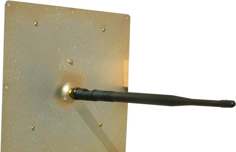
Click to zoom
Application Details
- Equipment Class
- AMP - Amplifier
- Date of Grant
- May 20, 2012
- Application Purpose
- Original Equipment
- Date of Application
- May 20, 2012
- Equipment Note
- SkySite Voice Repeater
- Frequency Range
- 940.00000000 - 941.00000000
- Company
- Space Data Corporation
- Country
- United States
Documents & Files
Document Text
Text extracted from the exhibit documents filed with the FCC. Open a document above to read the original.
Users Manual
- 1 - Space Data Corporation Confidential and proprietary information ________________________________________________________________________ Space Data Corporation SkySite System Operators Instructions Model SK8-900 SkySite Model GST-900 Ground Station Space Data Corporation 2535 W. Fairview St. Suite 101 Chandler, Arizona 85224 February 2012 - 2 - Space Data Corporation Confidential and proprietary information 1.0 Introduction. The Space Data Corporation SkySite network is designed to provide wireless paging service to remote areas that are not practically serviced by traditional terrestrial communication towers. This paging coverage is accomplished by mounting the functional equivalent of a communications tower on a high altitude weather balloon thereby overcoming service limitations. The SkySite Network consists of 5 subsystems listed below. 1. SkySite Platform 2. Launch Facilities 3. Ground Station 4. Network Control Center. 5. SkySite Control Center Wi r el es s Da t a Carriers Wi r el es s Voice Carriers Netw ork Control Center - Carrier Gateway s - Capacity Forecasting - Dev ice Location - Net work Management - ReFLEX - Mobitex - DataTac - GSM - CDMA - IDEN - TDMA Sky Sit e™ Control Center - Sky Sit e™ Locat ion and St at us - Sky Sit e™ Ant enna Tracking - Sky Sit e™ Cov erage Forecast ing - Sky Sit e™ Manual Commanding - Met eorological Dat a Processing WAN t o Ground St at ions Ground Stations - Transmit t er - Receiv er - Antenna - Ant enna Cont roller Sky Sit e™ Platforms - Sky Site™ DSP - Sky Site™ RF Circuitry - Sky Sit e™ Cont rol Processor - GPS Receiv er - Sky Sit e™ Vent - Sky Site™ Ballast - Sky Sit e™ Ant enna Launch Facilities - Sky Sit e™ Plat f orms - Supply of Lif t ing Gas - Weat her Balloons Figure 1.1: The SkySite Network This document is a summary of the procedures used to deploy and operate the SkySite network. All equipment shown is manufactured, operated and serviced by Space Data Corporation and is therefore meant for internal use only. 2.0 Pre-Launch Control Center operations are managed through the use of several Space Data Corp. proprietary software applications. These client applications run from EPS (Engineering Programming Software) server: GST (Ground Station) . The GST maintains the communication link from the ground to the SkySite. The GST also monitors and controls ground station functions such as - 3 - Space Data Corporation Confidential and proprietary information antenna auto-tracking, Receive signal strength, TX and RX power levels and frequency correction. SkySite client . Monitors SkySite performance such as TX and RX power levels, GPS position, battery current and voltage, and AH consumed. Vent ballast controls and accumulated values release command. Mapping client . This application utilizes the GPS coordinates sent from the SkySite and superimposes it on mapping software. Terrain and population density are easily determined from this screen and is used to plan recovery of the payload. The mapping client also has predictive capability. Using wind speed and direction information obtained on ascent, the software can predict where a SkySite will land if release at that moment from the balloon and descends using its parachute. 2.1 Pre-flight client preparation Start all GST (Ground Station Transceiver) and SKS (SkySite) clients. Both software applications should connect to the EPS (Engineering Programming Software) server. During operation each client should appear as shown in figures 2.1 and 2.2 below. Figure 2.1 – GST Client Screen - 4 - Space Data Corporation Confidential and proprietary information Figure 2.2 – SKS Client Screen Determine the type of antenna used by the Ground station in operation. There are only two types of antennas used: 1. Omi-directional antenna (Max. Gain of 3dBi) 2. Yagi antenna (Max. Gain of 10dBi) Caution: In order to comply with FCC Part 24 and RF (Radio Frequency) exposure limits of this product the maximum GST ERP (Effective Radiated Power) must not exceed 7 Watts (38.45dBm). Transmit power levels are shown in the bottom left corner of the GST client in the “TX GLP HPA STATUS” box. This value does not include the directional gain of the antenna. Therefore the maximum permissible power levels into the antenna as are as follows: 1. Using the Omni-directional antenna the maximum power is 35dBm. 2. Using the high gain Yagi antenna the maximum power is 28dBm. - 5 - Space Data Corporation Confidential and proprietary information • Start all GST and SKS clients. Ensure that GST clients connect to EPS server. On GST Client open the GLP RSSI and GPS screens • On the SKS Client open the following screens: GPS. GLP RSSI. Altitude vs. heading graphs. Altitude vs. Horizontal speed. Vertical speed graph. • Check Antenna Control: Disable tracking Ensure client is in “remote tracking” mode. For each GST client slew antenna in azimuth and elevation. Point antenna toward launch site at 0 degrees elevation. • Start GPS client on mapping PC and ensure it connects to EPS server. The GPS client started must correspond to the GST that will be used to control the payload. Figure 2.3 – Mapping Client Screen - 6 - Space Data Corporation Confidential and proprietary information • Start predictor software on mapping PC • Start Delorme payload and predictor programs on mapping PC. • Start Delorme payload and predictor programs on mapping PC. The mapping client should look like figure 2.3 as shown above. 3.0 Balloon Fill Steps 3.1 Initial Preparation • Arrive 1 hours before scheduled launch • Obtain pre-flight checklist • Turn on handheld radio for communication with local airport traffic (if applicable) • Verify channel and that comms are operating Figure 3.1 – Ground Wire clip 3.2 Area Preparation • Remove any obstacles from launch area • Place launch table in middle of area • Remove protective cover from launch table • Use brush to sweep off any debris from table • Attach ground wire from wall (Figure 2.1) to ground lug on table wrapp…
Text truncated - open the document above for the full version.
Cover Letter(s)
10 February 2012 Federal Communications Commission Authorization & Evaluation Division 7345 Oakland Mills Road Columbia, Maryland 21046 Re: Agent Authorization To Whom It May Concern: This letter will authorize Compliance Testing LLC to act as our Agent in all FCC matters. This appointment is effective until otherwise notified by us. This is to advise that we are in full compliance with the Anti-Drug Abuse Act. The Applicant is not subject to a denial of federal benefits pursuant to Section 5301 of the Anti-Drug Abuse Act of 1988, 21 USC 862, and no party to the application is subject to a denial of federal benefits pursuant to that section. Space Data Corporation Jerry Quenneville Vice President, Business Development
Cover Letter(s)
February 12, 2012 Federal Communications Commission EQUIPMENT APPROVAL SERVICES P.O. Box 358315 Pittsburgh, PA 15251-5313 ATTN: Authorization & Evaluation Division PER: 47 CFR 0.457 and 0.459 RE: RY9SK8900 Pursuant to Sections 0.457(d)(1)(ii) and 0.459 of the Commission’s Rules, the Applicant hereby requests confidential treatment of some of the information accompanying this Application as listed below. Specifically: Schematics Block diagrams Theory of Operation Parts lists Tune-up information These materials contain trade secrets and proprietary information not customarily released to the public and the public disclosure of these matters might be harmful to the Applicant and provide unjustified benefits to its competitors. The Applicant understands that pursuant to Rule 0.457(d)(1)(ii) disclosure of this Application and all accompanying documentation will not be made before the date of the Grant for this Application. Sincerely, Space Data Corporation Jerry Quenneville Vice President, Business Development
Cover Letter(s)
February 15, 2012 Federal Communications Commission Authorization and Evaluation Division 7435 Oakland Mills Road Columbia, MD 21046 ATTN: OET Department FCC ID: RY9SK8900 To Whom It May Concern: Space Data Corporation is submitting an Original Application for its Model: SK8-900 under FCC ID: RY9SK8900. There are/were no hardware or electrical modifications made to the Transmitter portion of this device, Model: SKS-900, that was originally certified on the commission date of April 15, 2004, FCC ID: RY9SKS900. Therefore the original Test Reports are being submitted as part of the new certification. Please contact me if you have any questions or need further information regarding this application. Sincerely, Jerry Quenneville Vice President, Business Development
Cover Letter(s)
Page 1 of 2 FCC ID: RY9SK8900 CT Project: TCB-p1220002 From: Chris Harvey Date: March 2, 2012 1. The manual specifies the Omni antenna and the High Gain Yagi antenna. There are photos of Antenna 2 and Antenna 4, but no cross reference to the names. The RF report MFA p0430001 indicated Radiated measurements with Whip and Hemispherical antennas. Are there only 2 possible antennas? Customer Response - We have apparently created some confusion between antennas used on the SkySite high altitude platform versus what’s used on the ground-based control station. There are three antennas that are used on the SkySite platform: the two depicted in the referenced photos and a third high gain antenna. High gain is a relative term in that the third antenna, a 5-element vertically oriented collinear array, provides about 6 dBd gain and slightly down-tilted pattern with gain primarily to the horizon. 2. The Operations Manual indicates operation in a ‘recovery frequency’ but does not provide any details of what this means. Please provide more information on the recovery frequency operations. Customer Response - Space Data owns licenses for several nationwide 900 MHz channels. A ‘recovery frequency’ is one that is used primarily at mission termination so as not to interfere with other channels set aside as operational frequencies. Operational frequencies are the ones programmed into user devices for communication through a SkySite platform. Recovery frequencies, which are not programmed into user devices, are used to track a SkySite platform to the ground once its high altitude mission is complete. 3. The recovery process indicates setting power to 33dBm, but this seems like it would be non-compliant is using the high gain 10dBi Yagi antenna. Customer Response - This refers to setting a SkySite transmit frequency, which is in the 930-931 MHz or 940-941 MHz range. The 33 dBm power level would be set on the SkySite high altitude platform, which is the base station or “tower” (albeit a very tall tower) in our system. While we cannot transmit the full 3,500-watt maximum allowed for towers in NPCS, there is a waiver in place that allows us to transmit up to 190 watts. The Yagi is only used with our ground station which operates in the 901-902 MHz portion of NPCS. We abide by the 7-watt ERP limit by limiting our transmit power to 28 dBm when using the Yagi, as specified on page 4 of the SkySite System Operators Instructions. 4. How does the user determine which antenna type is configured with a particular setup? Customer Response - Our standard SkySite antenna is the half-wave vertical dipole (“rubber duck”) depicted as Antenna 4 in the supplied photos. Antenna 2 is rarely if ever used, having been replaced by the 5-element collinear array. Attached is a photo (“Antenna 3”) of the collinear array suspended below a SkySite platform. A small quantity of collinear array antennas are available to launch teams if directed to change the antenna for a particular flight, but nearly all flights use Antenna 4. 5. Please note that the RF Test report P1220002 indicated 971.3% humidity. Please correct. CT - The typographical error – The FCC Part 24 Test Report has been revised. The Rev 2.0 has been uploaded for your review. Page 2 of 2 6. The conducted RF power in the 901-902 MHz band is 7Watts (38.45dBm) (from the Form 731), and the Yagi antenna has 10dBi gain. It seems possible that the device could be setup to operate outside of compliance. Please note that ERP is theoretically Conducted Power (dBm) + Antenna Gain (dBi) – 2.15dB. CT – Operation in the frequency band of 901-902 MHz is for the ground station only which is handled under a separate FCC ID from 2004. The 731 Form has been edited to remove this information. The revised 731 Form has been uploaded for your review. The 901-902 is a receive only band for this EUT. 7. The MPE exhibit was for original FCC ID and used only 3dBi antenna, and had 100cm separation, but amended pages has 25cm separation, but still 3dBi antenna. What about the 10dBi Yagi? What about the 7W operation at 901-902MHz? CT - Operation in the frequency band of 901-902 MHz is for the ground station only which is handled under a separate FCC ID from 2004. The 731 Form has been edited to remove this information. The revised 731 Form has been uploaded for your review. The 901-902 is a receive only band for this EUT. 8. There are 3 RF reports: MFA p0430001, d0440002 dated April 5, 2004, PCB Operations for 940.3675MHz and 930.010 MHz MFA p0430001, d0440002 dated April 13, 2004, 4 amended pages p1220002, dated February 8, 2012, AMP operations 930.5 & 940.5MHz, likely repeater operation There does not seem to be any test report submitted for the operations at 901-902MHz 7Watts AMP as shown on the Form 731. These are the parameters for the Accessory System Control Transmitter FCC ID: RY9GST900. Is this just a coincidence? CT - Operation in the frequency band of 901-902 MHz is for the ground station only which is handled under a separate FCC ID from 2004. The 731 Form has been edited to remove this information. The revised 731 Form has been uploaded for your review. The 901-902 is a receive only band for this EUT. 9. From the test reports and previous approvals it appears that the 901-902 MHz operates as AMP and 930-931 MHz and 940-941MHz operates as PCB. CT – The device operated under two equipment classifications in the 930-931 / 940-941 bands. PCB and AMP The 901-902 is a receive only band for this EUT. 10. The Block Diagram only shows the SKS-900 operations for 930-940 MHz. This block is also included in the Operational Description. If this device also operates in the 901-902MHz band, please update this to include all the operations of the SK8-900. CT – The only bands of operation are 930-931 / 940-941. The 901-902 is a receive only band for this EUT. Response by: Customer and John Erhard Submitted by: Karen Springer Date: April 18, 2012
External Photos
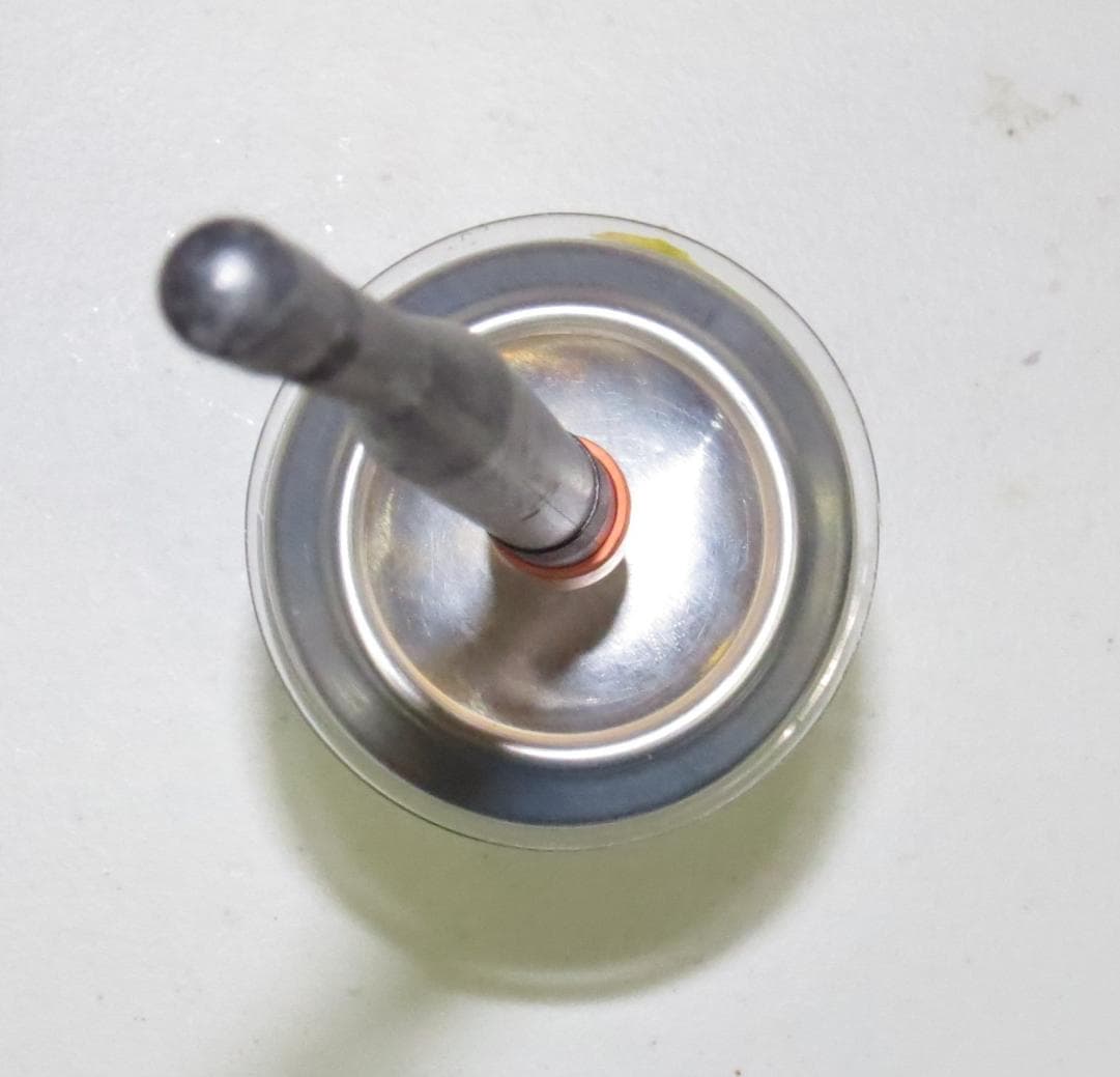
SkySite Photographs SkySite – Front view SkySite – Left Side View SkySite – Rear View SkySite – Right Side View SkySite – Top View SkySite – Bottom View
ID Label/Location Info
Space Data Corporation – Confidential and Proprietary Information Space Data Corporation’s grantee code “RY9” is displayed with the SkySite model number as FCC ID “RY9SK8900” as shown in the figure below: FCC ID: RY9SK8900 Model: SK8-900 This device complies with Part 15 of the FCC Rules. Operation is subject to the following two conditions: 1.) This device may not cause harmful interference, and 2.) This device must accept any interference that may be received, including interference that may cause undesired operation Made in U.S.A. FCC ID and Compliance Statement label FCC Label placement on SkySite product Space Data Corporation ®
Internal Photos
SkySite Printed Circuit Photographs GPS Antenna Printed Circuit – top GPS Antenna Printed Circuit -bottom Battery Printed Circuit Board – top Battery Printed Circuit Board – bottom Flight computer – top Flight computer - bottom Auxiliary board top Auxiliary board – bottom Payload Electronics – open view Transceiver top view Bottom view Baseband Processor board – top view Baseband Processor – bottom view
Test Report
p1220002_FCC Part 24_Rev 2.0 Page 1 of 25 Test Report Prepared for: Space Data Corporation Model: SK8-900 Description: SkySite Voice Repeater (LMR Repeater/Extender) To FCC Rule Part 24D Date of Issue: February 8, 2012 On the behalf of the applicant: Space Data Corporation 2535 W. Fairview St. Suite 101 Chandler, AZ 85224 Attention of: Jerry Knoblach, Chairman/CEO Ph: (480)722-2100 Fax: (480) 403-0021 E-Mail: [email protected] Prepared by Compliance Testing, LLC 3356 N San Marcos Pl, Suite 107 Chandler, AZ 85225-7176 (866) 311-3268 phone / (480) 926-3598 fax www.compliancetesting.com Project No: p1220002 John Erhard Project Test Engineer This report may not be reproduced, except in full, without written permission from Compliance Testing All results contained herein relate only to the sample tested p1220002_FCC Part 24_Rev 2.0 Page 2 of 25 Test Report Revision History Revision Date Revised By Reason for Revision 1.0 February 8, 2012 John Erhard Original Document 2.0 March 5, 2012 John Erhard Correct typographical error in environmental conditions during testing. p1220002_FCC Part 24_Rev 2.0 Page 3 of 25 Table of Contents Description Page Standard Test Conditions and Engineering Practices 7 Radiated Spurious Emissions 9 Conducted Spurious Emissions 12 Intermodulation 14 Occupied Bandwidth 16 Output Power 18 Out of Band Rejection 20 Frequency Stability 23 Test Equipment Utilized 25 p1220002_FCC Part 24_Rev 2.0 Page 4 of 25 ILAC / A2LA Compliance Testing, LLC, has been accredited in accordance with the recognized International Standard ISO/IEC 17025:2005. This accreditation demonstrates technical competence for a defined scope and the operation of a laboratory quality management system (refer joint ISO-ILAC-IAF Communiqué dated January 2009) The tests results contained within this test report all fall within our scope of accreditation, unless noted below. Please refer to http://www.compliancetesting.com/labscope.html for current scope of accreditation. Testing Certificate Number: 2152.01 FCC OATS Reg, #933597 IC Reg. #2044A-1 Non-accredited tests contained in this report: N/A p1220002_FCC Part 24_Rev 2.0 Page 5 of 25 The Applicant has been cautioned as to the following 15.21: Information to the User The user’s manual or instruction manual for an intentional radiator shall caution the user that changes or modifications not expressly approved by the party responsible for compliance could void the user’s authority to operate the equipment. 15.27(a): Special Accessories Equipment marketed to a consumer must be capable of complying with the necessary regulations in the configuration in which the equipment is marketed. Where special accessories, such as shielded cables and/or special connectors are required to enable an unintentional or intentional radiator to comply with the emission limits in this part, the equipment must be marketed with, i.e. shipped and sold with, those special accessories. However, in lieu of shipping or packaging the special accessories with the unintentional or intentional radiator, the responsible party may employ other methods of ensuring that the special accessories are provided to the consumer, without an additional charge. Information detailing any alternative method used to supply the special accessories for a grant of equipment authorization or retained in the verification records, as appropriate. The party responsible for the equipment, as detailed in § 2.909 of this chapter, shall ensure that these special accessories are provided with the equipment. The instruction manual for such devices shall include appropriate instructions on the first page of text concerned with the installation of the device that these special accessories must be used with the device. It is the responsibility of the user to use the needed special accessories supplied with the equipment. p1220002_FCC Part 24_Rev 2.0 Page 6 of 25 Sub-part 2.1033(c)(14): Test and Measurement Data All tests and measurement data shown were performed in accordance with FCC Rules and Regulations, Volume II, Part 2, Sub-part J, Sections 2.947, 2.1033(c), and the FCC AMPLIFIER, BOOSTER, AND REPEATER - BASIC ITEMS Measurement Guide p1220002_FCC Part 24_Rev 2.0 Page 7 of 25 Standard Test Conditions and Engineering Practices Except as noted herein, the following conditions and procedures were observed during the testing. In accordance with ANSI/C63.4-2009, and unless otherwise indicated in the specific measurement results, the ambient temperature of the actual EUT was maintained within the range of 10° to 40°C (50° to 104°F) unless the particular equipment requirements specify testing over a different temperature range. Also, unless otherwise indicated, the humidity levels were in the range of 10% to 90% relative humidity. Environmental Conditions Temperature (deg C) Humidity (%) Pressure (mbar) 25.00 27.90 971.300 Accessories: Qty Desc Mfg Model S/N 1 Active GPS Antenna System N/A N/A N/A 1 Laptop with System Control Software N/A N/A N/A 1 System Control Transmitter Space Data FCC ID: RY9GST900 N/A Cables: Standard RF cables as necessary Measurement results, unless otherwise noted, are worst-case measurements. p1220002_FCC Part 24_Rev 2.0 Page 8 of 25 Test Result Summary Test Name Pass, Fail, N/A Comments Radiated Spurious Emissions Pass Conducted Spurious Emissions Pass Intermodulation Pass Occupied Bandwidth Pass Output power Pass Out of Band Rejection Pass Frequency Stability Pass p1220002_FCC Part 24_Rev 2.0 Page 9 of 25 Radiated Spurious Emissions Name of Test: Radiated Spurious Emissions Engineer: John Erhard Test Equipment Utilized: i00103, i00331, i00348, i00091 Test Date: 2/6/2012 Test Procedure A) Connect the equipment as illustrated B) Adjust the spectrum analyzer for the following settings: 1) Resolution Bandwidth 100 kHz (< 1 GHZ), 1 MHZ (> 1GHz) unless otherwise specified. 2) Video Bandwidth ≥ 3 times Resolution Bandwidth 3) Sweep Speed ≤2000 Hz/second 4) Detector Mode = Average C) Place the transm…
Text truncated - open the document above for the full version.
Test Report
FCC ID: RY9SKS900 Transmitter Certification of FCC ID: RY9SKS900 Model: SKS-900 to Federal Communications Commission Rule Part(s) 24D, Confidentiality Date of report: April 5, 2004 On the Behalf of the Applicant: Space Data Corporation At the Request of: P.O. 20611 Space Data Corporation 460 S. Benson Lane, Suite 11-12 Chandler, AZ 85224 Attention of: Gerard J. Quenneville, Vice President Engineering (480) 722-2100; FAX: (480) 403-0021 [email protected] Bill McCullough Supervised by: Morton Flom, P. Eng. MFA p0430001, d0440002 FCC ID: RY9SKS900 List of Exhibits (FCC Certification (Transmitters) - Revised 9/28/98) Applicant: Space Data Corporation FCC ID: RY9SKS900 By Applicant: 1. Letter of Authorization x 2. Confidentiality Request: 0.457 And 0.459 x 3. Identification Drawings, 2.1033(c)(11) x Label x Location of Label x Compliance Statement x Location of Compliance Statement 4. Photographs, 2.1033(c)(12) x 5. Documentation: 2.1033(c) (3) User Manual x (9) Tune Up Info x (10) Schematic Diagram x (10) Circuit Description x Block Diagram x Active Devices x 6. MPE Report x By M.F.A. Inc.: A. Testimonial & Statement of Certification MFA p0430001, d0440002 FCC ID: RY9SKS900 The Applicant has been cautioned as to the following: 15.21 Information to the User. The users manual or instruction manual for an intentional radiator shall caution the user that changes or modifications not expressly approved by the party responsible for compliance could void the user's authority to operate the equipment. 15.27(a) Special Accessories. Equipment marketed to a consumer must be capable of complying with the necessary regulations in the configuration in which the equipment is marketed. Where special accessories, such as shielded cables and/or special connectors are required to enable an unintentional or intentional radiator to comply with the emission limits in this part, the equipment must be marketed with, i.e. shipped and sold with, those special accessories. However, in lieu of shipping or packaging the special accessories with the unintentional or intentional radiator, the responsible party may employ other methods of ensuring that the special accessories are provided to the consumer, without additional charge. Information detailing any alternative method used to supply the special accessories for a grant of equipment authorization or retained in the verification records, as appropriate. The party responsible for the equipment, as detailed in § 2.909 of this chapter, shall ensure that these special accessories are provided with the equipment. The instruction manual for such devices shall include appropriate instructions on the first page of text concerned with the installation of the device that these special accessories must be used with the device. It is the responsibility of the user to use the needed special accessories supplied with the equipment. MFA p0430001, d0440002 FCC ID: RY9SKS900 Table of Contents Rule Description Page . Test Report 1 2.1033(c) General Information Required 2 2.1033(c)(14) Rule Summary 5 . Standard Test Conditions and Engineering Practices 6 2.1046(a) Carrier Output Power (Conducted) 7 2.1046(a) ERP Carrier Power (Radiated) 9 2.1053(a) Field Strength of Spurious Radiation 11 2.1049(c)(1) Emission Masks (Occupied Bandwidth) 15 2.1055(a)(1) Frequency Stability (Temperature Variation) 24 2.1055(b)(1) Frequency Stability (Voltage Variation) 27 2.202(g) Necessary Bandwidth and Emission Bandwidth 28 MFA p0430001, d0440002 FCC ID: RY9SKS900 Page Number 1 of 28. Required information per ISO/IEC Guide 25-1990, paragraph 13.2: a) Test Report b) Laboratory: (FCC: 31040/SIT) (Canada: IC 2044) M. Flom Associates, Inc. 3356 N. San Marcos Place, Suite 107 Chandler, AZ 85225 c) Report Number: d0440002 d) Client: Space Data Corporation 460 S. Benson Lane, Suite 11-12 Chandler, AZ 85224 e) Identification: SKS-900 FCC ID: RY9SKS900 EUT Description: Narrow Band PCS f) EUT Condition: Not required unless specified in individual tests. g) Report Date: April 5, 2004 EUT Received: March 1, 2004 h, j, k): As indicated in individual tests. i) Sampling method: No sampling procedure used. l) Uncertainty: In accordance with MFA internal quality manual. m) Supervised by: Morton Flom, P. Eng. n) Results: The results presented in this report relate only to the item tested. o) Reproduction: This report must not be reproduced, except in full, without written permission from this laboratory. MFA p0430001, d0440002 FCC ID: RY9SKS900 Page Number 2 of 28. List of General Information Required for Certification In Accordance with FCC Rules and Regulations, Volume II, Part 2 and to 24D, Confidentiality Sub-part 2.1033 (c)(1): Name and Address of Applicant: Space Data Corporation 460 S. Benson Lane, Suite 11-12 Chandler, AZ 85224 Manufacturer: Applicant (c)(2): FCC ID: RY9SKS900 Model Number: SKS-900 (c)(3): Instruction Manual(s): Please see attached exhibits (c)(4): Type of Emission: 10K0F1D (c)(5): Frequency Range, MHz: 901 to 941 (c)(6): Power Rating, Watts: 2.0 Switchable Variable x N/A FCC Grant Note: BE - The output power is continuously variable from the value listed in this entry to 15%- 20% of the value listed. (c)(7): Maximum Power Rating, Watts: 190 W (per FCC MOO DA01-2132 dtd September 12, 2001) DUT Results: Passes x Fails MFA p0430001, d0440002 FCC ID: RY9SKS900 Page Number 3 of 28. NIST MFA p0430001, d0440002 FCC ID: RY9SKS900 Page Number 4 of 28. Subpart 2.1033 (continued) (c)(8): Voltages & currents in all elements in final RF stage, including final transistor or solid-state device: Collector Current, A = per manual Collector Voltage, Vdc = per manual Supply Voltage, Vdc = 24 vdc (c)(9): Tune-Up Procedure: Please see attached exhibits (c)(10): Circuit Diagram/Circuit Description: Including description of circuitry & devices provided for determining and stabilizing frequency, for suppression of spurious radiation, for limiting modulation and limiting power. Please see attached exhibits (c)(11): La…
Text truncated - open the document above for the full version.
Test Report
FCC ID: RY9SKS900 Page Number 2 of 28. AMENDED April 13, 2004 List of General Information Required for Certification In Accordance with FCC Rules and Regulations, Volume II, Part 2 and to 24D, Confidentiality Sub-part 2.1033 (c)(1): Name and Address of Applicant: Space Data Corporation 460 S. Benson Lane, Suite 11-12 Chandler, AZ 85224 Manufacturer: Applicant (c)(2): FCC ID: RY9SKS900 Model Number: SKS-900 (c)(3): Instruction Manual(s): Please see attached exhibits (c)(4): Type of Emission: 10K0F1D (c)(5): Frequency Range, MHz: 930 to 941 (c)(6): Power Rating, Watts: 2.0 Switchable x Variable N/A (c)(7): Maximum Power Rating, Watts: 190 W (Defined as Base Station per FCC MOO DA01-2132 dtd September 12, 2001) DUT Results: Passes x Fails MFA p0430001, d0440002 FCC ID: RY9SKS900 Page Number 16 of 28. AMENDED April 13, 2004 Name of Test: Emission Masks (Occupied Bandwidth) g0430050: 2004-Mar-22 Mon 10:24:00 State: 2:High Power Ambient Temperature: 23°C ± 3°C RES BW 30 kHzVBW 100 kHzSWP 20.0 msec ATTEN 10 dBREF -7.0 dBm 10 dB/ CENTER 941.00 MHz SPAN 2.00 MHz Power: HIGH Modulation: 6400 4FSK GAUSS WIDE BAND NOISE Rule Part 24.133 applies Performed by: David E. Lee, Lab Manager MFA p0430001, d0440002 FCC ID: RY9SKS900 Page Number 17 of 28. AMENDED April 13, 2004 Name of Test: Emission Masks (Occupied Bandwidth) g0430047: 2004-Mar-22 Mon 10:11:00 State: 2:High Power Ambient Temperature: 23°C ± 3°C f o -25.0kHz f o -30.7kHz 63dBc (20W) 24.9dBc f o f o -25.0kHz f o -30.7kHz 63dBc (20W) 24.9dBc f o 4 x 12.5kHz Channels 4 x 12.5kHz Channels Power: HIGH Modulation: 6400 4FSK GAUSSIAN FILTER Proposed channel plan uses one of 4 carriers for each 50kHz channel allocation. Sky Sites in different locations may use channels in the same 50kHz allocation without interference to other Part 24D users or each other. BOTH CHANNELS OF A CHANNEL ALLOCATION (Example of Mask for 50kHz Channels with 2W + 10dBi antenna gain) Rule Part 24.133(a) applies Performed by: David E. Lee, Lab Manager MFA p0430001, d0440002 FCC ID: RY9SKS900 MFA p0430001, d0440002 Page Number 28 of 28. AMENDED April 13, 2004 Name of Test: Necessary Bandwidth and Emission Bandwidth Specification: 47 CFR 2.202(g) Modulation = 10K0F1D Necessary Bandwidth Calculation: Maximum Modulation (M), kHz 2.5 Maximum Deviation (D), kHz = 2.5 Constant Factor (K) = 1 Necessary Ban…
Text truncated - open the document above for the full version.
Contact Information
Applicant
Gerard J. Quenneville(Vice President, Business Development)
Technical Specifications
| # | Rule Parts | Frequency Range | Power Output | Emission | Tolerance |
|---|---|---|---|---|---|
| 2 | 24D | 940 MHz - 941 MHz | 2 W | 11K5F1D | 1 ppm |
Other Applications from Space Data Corporation
RY9SKS900MK2
May 27, 2013Narrowband PCS, Multi-Protocol SkySite
Equipment Class
PCB - PCS Licensed Transmitter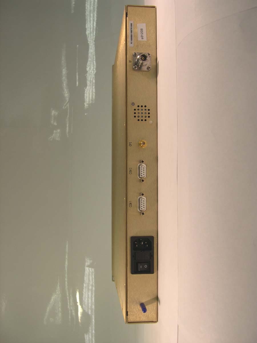
RY9GST900
Apr 19, 2004Narrow Band PCS
Equipment Class
PCB - PCS Licensed Transmitter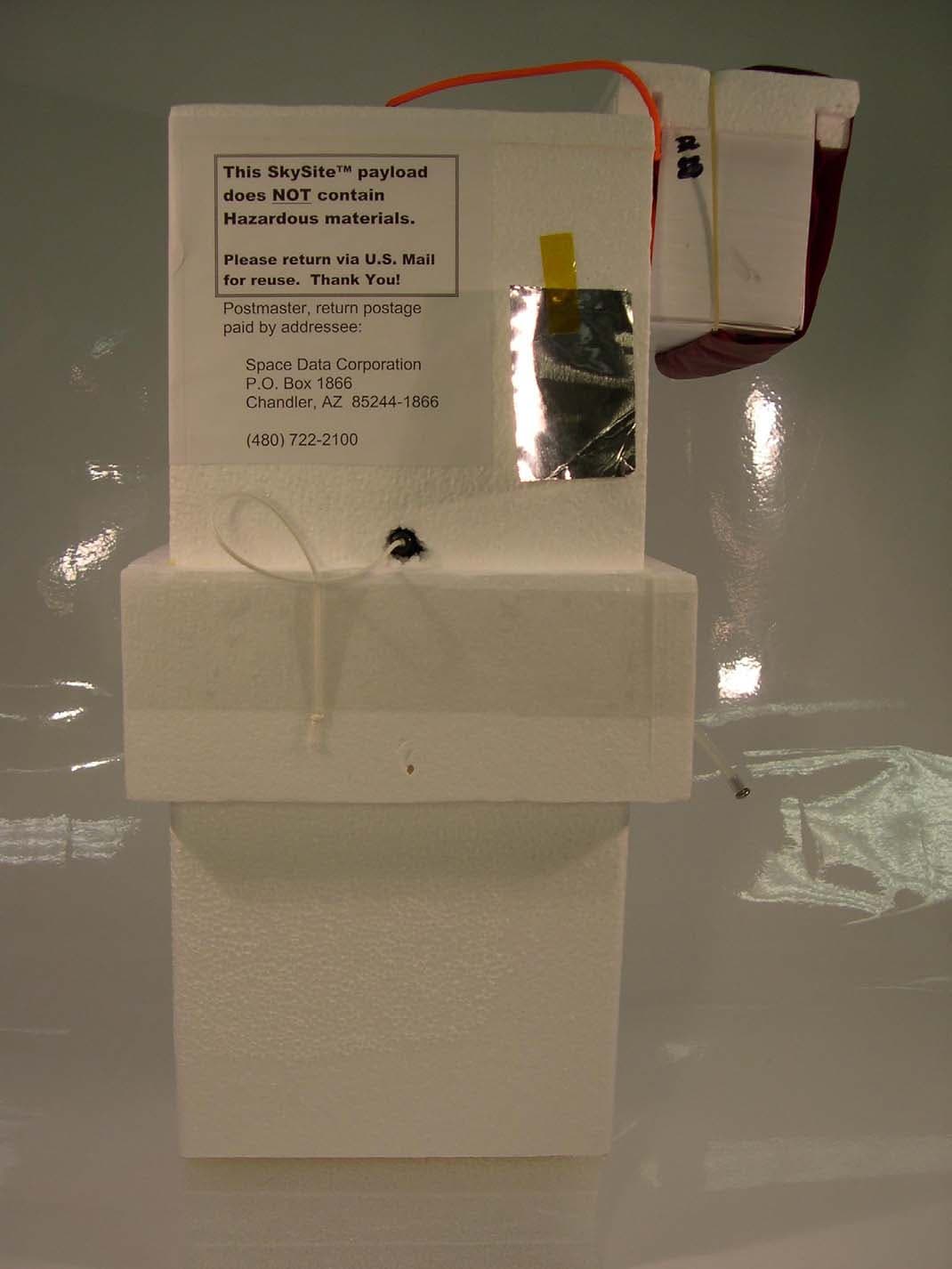
RY9SKS900
Apr 14, 2004Narrow Band PCS
Equipment Class
PCB - PCS Licensed Transmitter