RY9SKS900Narrow Band PCS
Space Data Corporation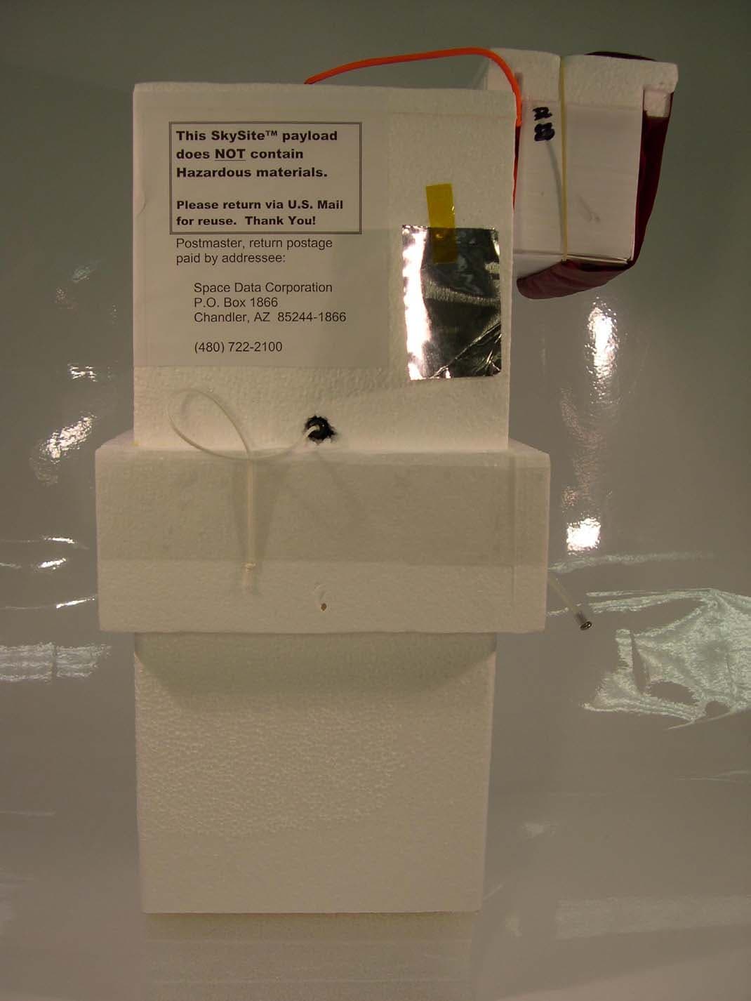
Click to zoom
Application Details
- Equipment Class
- PCB - PCS Licensed Transmitter
- Date of Grant
- Apr 14, 2004
- Application Purpose
- Original Equipment
- Date of Application
- Apr 14, 2004
- Equipment Note
- Narrow Band PCS
- Frequency Range
- 930.00000000 - 941.00000000
- Company
- Space Data Corporation
- Country
- United States
Documents & Files
Document Text
Text extracted from the exhibit documents filed with the FCC. Open a document above to read the original.
Users Manual
- 1 - Space Data Corporation Confidential and proprietary information Space Data Corporation ® ________________________________________________________________________ Space Data Corporation SkySite System Operators Instructions Model SKS-900 SkySite Model GST-900 Ground Station Space Data Corporation 460 S Benson Lane Suite 11-12 Chandler, Arizona 85224-5663 March, 2004 - 2 - Space Data Corporation Confidential and proprietary information 1.0 Introduction. The Space Data Corporation SkySite network is designed to provide wireless paging service to remote areas that are not practically serviced by traditional terrestrial communication towers. This paging coverage is accomplished by mounting the functional equivalent of a communications tower on a high altitude weather balloon thereby overcoming service limitations. The SkySite Network consists of 5 subsystems listed below. 1. SkySite Platform 2. Launch Facilities 3. Ground Station 4. Network Control Center. 5. SkySite Control Center Wireless Data Carriers Wireless Voice Carriers Network Control Center - Carrier Gateways - Capacity Forecasting - Device Location - Network Management - ReFLEX - Mobitex - DataTac - GSM - CDMA - IDEN - TDMA SkySite™ Control Center - SkySite™ Location and Status - SkySite™ Antenna Tracking - SkySite™ Coverage Forecasting - SkySite™ Manual Commanding - Meteorological Data Processing WAN to Ground Stations Ground Stations - Transmitter - Receiver - Antenna - Antenna Controller SkySite™ Platforms - SkySite™ DSP - SkySite™ RF Circuitry - SkySite™ Control Processor - GPS Receiver - SkySite™ Vent - SkySite™ Ballast - SkySite™ Antenna Launch Facilities - SkySite™ Platforms - Supply of Lifting Gas - Weather Balloons Figure 1.1: The SkySite Network This document is a summary of the procedures used to deploy and operate the SkySite network. All equipment shown is manufactured, operated and serviced by Space Data Corporation and is therefore meant for internal use only. - 3 - Space Data Corporation Confidential and proprietary information 2.0 Launch Control Center operations are managed through the use of several Space Data Corp. proprietary software applications. These client applications run from EPS (Engineering Programming Software) server: GST (Ground Station). The GST maintains the communication link from the ground to the SkySite. The GST also monitors and controls ground station functions such as antenna auto-tracking, Receive signal strength, TX and RX power levels and frequency correction. SkySite client. Monitors SkySite performance such as TX and RX power levels, GPS position, battery current and voltage, and AH consumed. Vent ballast controls and accumulated values release command. Mapping client. This application utilizes the GPS coordinates sent from the SkySite and superimposes it on mapping software. Terrain and population density are easily determined from this screen and is used to plan recovery of the payload. 2.1 Pre-flight client preparation Start all GST (Ground Station Transceiver) and SKS (SkySite) clients. Both software applications should connect to the EPS (Engineering Programming Software) server. Determine the type of antenna used by the Ground station in operation. There are only two types of antennas used: 1. Omi-directional antenna (Max. Gain of 3dBi) 2. Yagi antenna (Max. Gain of 10dBi) Caution: In order to comply with FCC Part 24 and RF (Radio Frequency) exposure limits of this product the maximum GST ERP (Effective Radiated Power) must not exceed 7 Watts (38.45dBm). Transmit power levels are shown in the bottom left corner of the GST client in the “TX GLP HPA STATUS” box. This value does not include the directional gain of the antenna. Therefore the maximum permissible power levels into the antenna as are as follows: 1. Using the Omni-directional antenna the maximum power is 35dBm. 2. Using the high gain Yagi antenna the maximum power is 28dBm. - 4 - Space Data Corporation Confidential and proprietary information • Start all GST and SKS clients. Ensure that GST clients connect to EPS server. On GST Client open the GLP RSSI and GPS screens • On the SKS Client open the following screens: GPS. GLP RSSI. Altitude vs. heading graphs. Altitude vs. Horizontal speed. Vertical speed graph. • Check Antenna Control: Disable tracking Ensure client is in “remote tracking” mode. For each GST client slew antenna in azimuth and elevation. Point antenna toward launch site at 0 degrees elevation. • Start GPS client on mapping PC and ensure it connects to EPS server. The GPS client started must correspond to the GST that will be used to control the payload. • Start predictor software on mapping PC • Start Delorme payload and predictor programs on mapping PC. 2.2 Launch procedure: • Switch GST client to launch frequency • Watch RSSI level. When Rx Sync has indicator turn green call launch team and give them the OK to release the SkySite. • When SkySite is picked up by the GST and signal is stable call launch team and have them go to listen mode. • When you see the RSSI signal level drop on the SkySite enter command mode on GST. • Confirm auto hover is engaged and set for the correct altitude • Switch SkySite to operational frequency at high power: • On configuration screen select an operational frequency, select “non-volatile” and click set. • On the GST client go to the configuration screen and switch it’s frequency to the one that the SkySite is using and re-acquire the SkySite. • On the SkySite client go to the “configuration” screen and select an output power of 33 dB. Select “non-volatile” and click set. • Reduce the power of the SkySite to the minimum power required. Ensure that it is a “volatile” change. • Confirm that ReFLEX is enabled. - 5 - Space Data Corporation Confidential and proprietary information 3.0 Flight termination • When the useful life of the SkySite, turn command over to the recovery team and let them know the SkySite will be switching over to a recovery frequency. • Switch SkySite…
Text truncated - open the document above for the full version.
External Photos
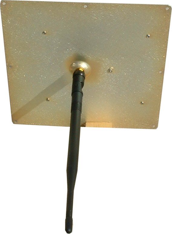
SkySite Photographs SkySite – Front view SkySite – Left Side View SkySite – Rear View SkySite – Right Side View SkySite – Top View SkySite – Bottom View
ID Label/Location Info
FCC Identification and Compliance Statement. An FCC identification and compliance label is affixed to the SkySite transceiver plate. The transceiver plate location was chosen since it is the most integral part of the SkySite product. Space Data Corporation’s grantee code “RY9” is displayed with the SkySite model number as FCC ID “RY9SKS900” as shown in the figure below: FCC ID: RY9SKS900 Model: SKS-900 This device complies with Part 15 of the FCC Rules. Operation is subject to the following two conditions: 1) This device may not cause harmful interference and 2) This device must accept any interference that may be received, including interference that may cause undesired operation.' Made in U.S.A. Space Data Corporation ® FCC ID and Compliance Statement label FCC Label placement on SkySite product
Internal Photos
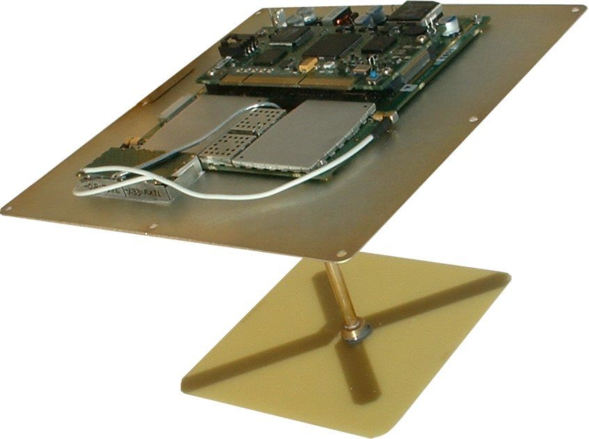
SkySite Printed Circuit Photographs GPS Antenna Printed Circuit – top GPS Antenna Printed Circuit -bottom Battery Printed Circuit Board – top Battery Printed Circuit Board – bottom Flight computer – top Flight computer - bottom Auxiliary board top Auxiliary board – bottom Payload Electronics – open view Transceiver top view Bottom view Baseband Processor board – top view Baseband Processor – bottom view
RF Exposure Info
FCC ID: RY9SKS900 Environmental Assessment for Mobiles/Fixed Base Station for FCC ID: FCC ID: RY9SKS900 Model: SKS-900 to Federal Communications Commission 47 CFR 1.1310 (MPE) Radiofrequency Radiation Exposure Limits Date Of Report: April 5, 2004 On the Behalf of the Applicant: Space Data Corporation At the Request of: P.O. 20611 Space Data Corporation 460 S. Benson Lane, Suite 11-12 Chandler, AZ 85224 Attention of: Gerard J. Quenneville, Vice President Engineering (480) 722-2100; FAX: (480) 403-0021 [email protected] Bill McCullough Supervised By: Morton Flom, P. Eng. MFA p0430001, d0440005 FCC ID: RY9SKS900 Table of Contents Rule Description Page . Test Report 1 . Identification of the Equipment Under Test 2 . Standard Test Conditions and Engineering Practices 4 1.1310 Environmental Assessment 5 MFA p0430001, d0440005 FCC ID: RY9SKS900 Page Number 1 of 7. Required information per ISO/IEC Guide 25-1990, paragraph 13.2: a) Test Report (Supplemental) b) Laboratory: (FCC: 31040/SIT) (Canada: IC 2044) M. Flom Associates, Inc. 3356 N. San Marcos Place, Suite 107 Chandler, AZ 85225 c) Report Number: d0440005 d) Client: Space Data Corporation 460 S. Benson Lane, Suite 11-12 Chandler, AZ 85224 e) Identification: SKS-900 FCC ID: RY9SKS900 Description: Narrow Band PCS f) EUT Condition: Not required unless specified in individual tests. g) Report Date: April 5, 2004 EUT Received: 2004-Mar-01 h, j, k): As indicated in individual tests. i) Sampling method: No sampling procedure used. l) Uncertainty: In accordance with MFA internal quality manual. m) Supervised by: Morton Flom, P. Eng. n) Results: The results presented in this report relate only to the item tested. o) Reproduction: This report must not be reproduced, except in full, without written permission from this laboratory. MFA p0430001, d0440005 FCC ID: RY9SKS900 Page Number 2 of 7. Identification of the Equipment Under Test (EUT) Name and Address of Applicant: Space Data Corporation 460 S. Benson Lane, Suite 11-12 Chandler, AZ 85224 Manufacturer: Applicant FCC ID: RY9SKS900 Model Number: SKS-900 Description: Narrow Band PCS Type of Emission: 10K0F1D Frequency Range, MHz: 901 to 941 Power Rating, Watts: 2.0 Switchable Variable x N/A Modulation: AMPS TDMA CDMA X OTHER Antenna: Helical Monopole X Whip Other Note: For RF Safety test antenna gain taken at the upper range of expected gain (i.e. 3 dBi) and RF Power set to highest nominal power across all channels. MFA p0430001, d0440005 FCC ID: RY9SKS900 Page Number 3 of 7. NIST MFA p0430001, d0440005 FCC ID: RY9SKS900 Page Number 4 of 7. Standard Test Conditions and Engineering Practices Except as noted herein, the following conditions and procedures were observed during the testing: In accordance with ANSI C63.4-1992/2000, section 6.1.9, and unless otherwise indicated in the specific measurement results, the ambient temperature of the actual EUT was maintained within the range of 10° to 40°C (50° to 104 °F) unless the particular equipment requirements specify testing over a different temperature range. Also, unless otherwise indicated, the humidity levels were in the range of 10% to 90% relative humidity. Prior to testing, the EUT was tuned up in accordance with the manufacturer's alignment procedures. All external gain controls were maintained at the position of maximum and/or optimum gain throughout the testing. Measurement results, unless otherwise noted, are worst-case measurements. MFA p0430001, d0440005 FCC ID: RY9SKS900 Page Number 5 of 7. Name of Test: Environmental Assessment Specification: FCC: 47 CFR 1.1310 Measurement Guide: ANSI/IEEE C95.1 1992 Test Equipment: Maximum Permissible Exposure (MPE) measurement system, consisting of: Narda 8717-1174R, Radiation meter Narda 8761D, E-field probe (300 kHz – 3 GHz) (Calibrated Feb-2003) Measurement Procedure: 1. The following measurements were performed with a Narda probe using ANSI/IEEE C95.1 as a guide. 2. Prior to making any measurements, the measurements system was calibrated in accordance with the manufacturer’s procedures. 3. The EUT’s radiating element (antenna) was placed on a 1 m tall table for ease of testing. For equipment normally operated on a metal surface, a ground plane was used. 4. The remaining equipment necessary to operate the EUT was maintained at a distance from the measurement arrangement suitable to minimize interference with the measurements. 5. The minimum safe distance was calculated from the formula Power Density = EIRP / 4πR 2 (Peak Watts/m 2 ). The calculation is shown with the measurement data. 6. With the EUT operating at maximum power, a search was initiated for worst case emissions with the probe raised and lowered over a range of 0.2 to 2 meters in height and over a horizontal plane of 0 o to 360 o . 7. Average values were calculated for the whole body (0.2- 2.0m), lower body (0.2-0.8m) and upper body (1.0-2.0m). Results: Attached. MFA p0430001, d0440005 FCC ID: RY9SKS900 Page Number 6 of 7. Test Setup: Maximum Permissible Exposure (MPE) MFA p0430001, d0440005 FCC ID: RY9SKS900 Page Number 7 of 7. Name of Test: R.F. Radiation Exposure FCC Rules: 1.1307, 1.1310, 1.1311, 2.1091 Description, EUT: See page 2 of Test Report 0.3-1.234 MHz: Limit [ mW/cm 2 ] = 100 1.34-30 MHz: Limit [ mW/cm 2 ] = (180/f 2 ) 30-300 MHz: Limit [ mW/cm 2 ] = 0.2 Limits: Uncontrolled Exposure 47 CFR 1.1310 Table 1, (B) 300-1500 MHz Limit [ mW/cm 2 ] = f/1500 1500-100,000 MHz: Limit [ mW/cm 2 ] = 1.0 Test Frequency, MHz 930.3675 Power, Conducted, W = 2.0 Antenna Gain = 3 dBi Antenna Model Helical Whip Power [W EIRP] = P [conducted] x G [antenna] = 4.0 Limit [mW/cm2] = 0.62 Limit [W/m2] = 10 x Limit [mW/cm2] = 6.20 Pre-test Calculations R [m] = [P [W EIRP] / (4π x Limit [W/m2] )] 1/2 = 0.243 X Narda 8717-1174R, Radiation Meter Narda 8760B, E-field probe (300 kHz – 1 GHz) Instruments X Narda 8761D, E-field probe (300 kHz – 3 GHz) Power Density, mW/cm 2 Freq. 930.3675 MHz Probe Height, m Distance 100 cm 2.0 0.030 1.8 0.046 1.6 0.089 1.4…
Text truncated - open the document above for the full version.
RF Exposure Info
FCC ID: RY9SKS900 Page Number 2 of 8. AMENDED April 10, 2004 Identification of the Equipment Under Test (EUT) Name and Address of Applicant: Space Data Corporation 460 S. Benson Lane, Suite 11-12 Chandler, AZ 85224 Manufacturer: Applicant FCC ID: RY9SKS900 Model Number: SKS-900 Description: Narrow Band PCS Type of Emission: 10K0F1D Frequency Range, MHz: 930 to 941 Power Rating, Watts: 2.0 Switchable Variable x N/A Modulation: AMPS TDMA CDMA X OTHER Antenna: Helical Monopole X Whip Other Note: For RF Safety test antenna gain taken at the upper range of expected gain (i.e. 3 dBi) and RF Power set to highest nominal power across all channels. MFA p0430001, d0440005
RF Exposure Info
FCC ID: RY9SKS900 Page Number 8 of 8. AMENDED April 12, 2004 Name of Test: R.F. Radiation Exposure FCC Rules: 1.1307, 1.1310, 1.1311, 2.1091 Description, EUT: See page 2 of Test Report 0.3-1.234 MHz: Limit [ mW/cm 2 ] = 100 1.34-30 MHz: Limit [ mW/cm 2 ] = (180/f 2 ) 30-300 MHz: Limit [ mW/cm 2 ] = 0.2 Limits: Uncontrolled Exposure 47 CFR 1.1310 Table 1, (B) 300-1500 MHz Limit [ mW/cm 2 ] = f/1500 1500-100,000 MHz: Limit [ mW/cm 2 ] = 1.0 Test Frequency, MHz 930.3675 Power, Conducted, W = 2.0 Antenna Gain = 3 dBi Antenna Model Helical Whip Power [W EIRP] = P [conducted] x G [antenna] = 4.0 Limit [mW/cm2] = 0.62 Limit [W/m2] = 10 x Limit [mW/cm2] = 6.20 Pre-test Calculations R [m] = [P [W EIRP] / (4π x Limit [W/m2] )] 1/2 = 0.243 X Narda 8717-1174R, Radiation Meter Narda 8760B, E-field probe (300 kHz – 1 GHz) Instruments X Narda 8761D, E-field probe (300 kHz – 3 GHz) Power Density, mW/cm 2 Freq. 930.3675 MHz Probe Height, m Distance 25 cm 2.0 0.075 1.8 0.115 1.6 0.223 1.4 0.383 1.2 0.498 1.0 0.525 0.8 0.495 0.6 0.425 0.4 0.338 Results at tested distances 0.2 0.263 Power Density Calculations: The measured power density readings were summed and the results divided by the number of readings to calculate the average. 930.3675 MHz Whole body average (0.2 - 0.8 m, mW/cm 2 ) = 0.334 Lower body average (0.2 - 0.8 m, mW/cm 2 ) = 0.380 Upper body average (1.0 - 2.0 m, mW/cm 2 ) = 0.303 Supervised By: Morton Flom, P. Eng. MFA p0430001, d0440005 FCC ID: RY9SKS900 MFA p0430001, d0440005 (The following will be placed in the Instruction Manual) Mandatory Safety Instructions to Installers & Users Use only manufacturer or dealer supplied antenna. Antenna Minimum Safe Distance: 25cm. Antenna Gain: 3dB referenced to isotropic. The Federal Communications Commission has adopted a safety standard for human exposure to RF (Radio Frequency) energy which is below the OSHA (Occupational Safety and Health Act) limits. Antenna Mounting: The antenna supplied by the manufacturer or radio dealer must not be mounted at a location such that during radio transmission, any person or persons can come closer than the above indicated minimum safe distance to the antenna i.e. 25cm To comply with current FCC RF Exposure limits, the antenna must be installed at or exceeding the minimum safe distance shown above, and in accordance with the requirements of the antenna manufacturer or supplier. Base Station Installation: The antenna should be fixed-mounted on an outdoor permanent structure. RF Exposure compliance must be addressed at the time of installation. Antenna Substitution: Do not substitute any antenna for the one supplied or recommended by the manufacturer or radio dealer. You may be exposing person or persons to excess radio frequency radiation. You may contact your radio dealer or the manufacturer for further instructions. Warning: Maintain a separation distance from the antenna to a person(s) of at least 25cm. You, as the qualified end-user of this radio device must control the exposure conditions of bystanders to ensure the minimum separation distance (above) is maintained between the antenna and nearby persons for satisfying RF Exposure compliance. The operation of this transmitter must satisfy the requirements of Occupational/Controlled Exposure Environment, for work-related use. Transmit only when person(s) are at least the minimum distance from the properly installed, externally mounted antenna.
Test Report
FCC ID: RY9SKS900 Transmitter Certification of FCC ID: RY9SKS900 Model: SKS-900 to Federal Communications Commission Rule Part(s) 24D, Confidentiality Date of report: April 5, 2004 On the Behalf of the Applicant: Space Data Corporation At the Request of: P.O. 20611 Space Data Corporation 460 S. Benson Lane, Suite 11-12 Chandler, AZ 85224 Attention of: Gerard J. Quenneville, Vice President Engineering (480) 722-2100; FAX: (480) 403-0021 [email protected] Bill McCullough Supervised by: Morton Flom, P. Eng. MFA p0430001, d0440002 FCC ID: RY9SKS900 List of Exhibits (FCC Certification (Transmitters) - Revised 9/28/98) Applicant: Space Data Corporation FCC ID: RY9SKS900 By Applicant: 1. Letter of Authorization x 2. Confidentiality Request: 0.457 And 0.459 x 3. Identification Drawings, 2.1033(c)(11) x Label x Location of Label x Compliance Statement x Location of Compliance Statement 4. Photographs, 2.1033(c)(12) x 5. Documentation: 2.1033(c) (3) User Manual x (9) Tune Up Info x (10) Schematic Diagram x (10) Circuit Description x Block Diagram x Active Devices x 6. MPE Report x By M.F.A. Inc.: A. Testimonial & Statement of Certification MFA p0430001, d0440002 FCC ID: RY9SKS900 The Applicant has been cautioned as to the following: 15.21 Information to the User. The users manual or instruction manual for an intentional radiator shall caution the user that changes or modifications not expressly approved by the party responsible for compliance could void the user's authority to operate the equipment. 15.27(a) Special Accessories. Equipment marketed to a consumer must be capable of complying with the necessary regulations in the configuration in which the equipment is marketed. Where special accessories, such as shielded cables and/or special connectors are required to enable an unintentional or intentional radiator to comply with the emission limits in this part, the equipment must be marketed with, i.e. shipped and sold with, those special accessories. However, in lieu of shipping or packaging the special accessories with the unintentional or intentional radiator, the responsible party may employ other methods of ensuring that the special accessories are provided to the consumer, without additional charge. Information detailing any alternative method used to supply the special accessories for a grant of equipment authorization or retained in the verification records, as appropriate. The party responsible for the equipment, as detailed in § 2.909 of this chapter, shall ensure that these special accessories are provided with the equipment. The instruction manual for such devices shall include appropriate instructions on the first page of text concerned with the installation of the device that these special accessories must be used with the device. It is the responsibility of the user to use the needed special accessories supplied with the equipment. MFA p0430001, d0440002 FCC ID: RY9SKS900 Table of Contents Rule Description Page . Test Report 1 2.1033(c) General Information Required 2 2.1033(c)(14) Rule Summary 5 . Standard Test Conditions and Engineering Practices 6 2.1046(a) Carrier Output Power (Conducted) 7 2.1046(a) ERP Carrier Power (Radiated) 9 2.1053(a) Field Strength of Spurious Radiation 11 2.1049(c)(1) Emission Masks (Occupied Bandwidth) 15 2.1055(a)(1) Frequency Stability (Temperature Variation) 24 2.1055(b)(1) Frequency Stability (Voltage Variation) 27 2.202(g) Necessary Bandwidth and Emission Bandwidth 28 MFA p0430001, d0440002 FCC ID: RY9SKS900 Page Number 1 of 28. Required information per ISO/IEC Guide 25-1990, paragraph 13.2: a) Test Report b) Laboratory: (FCC: 31040/SIT) (Canada: IC 2044) M. Flom Associates, Inc. 3356 N. San Marcos Place, Suite 107 Chandler, AZ 85225 c) Report Number: d0440002 d) Client: Space Data Corporation 460 S. Benson Lane, Suite 11-12 Chandler, AZ 85224 e) Identification: SKS-900 FCC ID: RY9SKS900 EUT Description: Narrow Band PCS f) EUT Condition: Not required unless specified in individual tests. g) Report Date: April 5, 2004 EUT Received: March 1, 2004 h, j, k): As indicated in individual tests. i) Sampling method: No sampling procedure used. l) Uncertainty: In accordance with MFA internal quality manual. m) Supervised by: Morton Flom, P. Eng. n) Results: The results presented in this report relate only to the item tested. o) Reproduction: This report must not be reproduced, except in full, without written permission from this laboratory. MFA p0430001, d0440002 FCC ID: RY9SKS900 Page Number 2 of 28. List of General Information Required for Certification In Accordance with FCC Rules and Regulations, Volume II, Part 2 and to 24D, Confidentiality Sub-part 2.1033 (c)(1): Name and Address of Applicant: Space Data Corporation 460 S. Benson Lane, Suite 11-12 Chandler, AZ 85224 Manufacturer: Applicant (c)(2): FCC ID: RY9SKS900 Model Number: SKS-900 (c)(3): Instruction Manual(s): Please see attached exhibits (c)(4): Type of Emission: 10K0F1D (c)(5): Frequency Range, MHz: 901 to 941 (c)(6): Power Rating, Watts: 2.0 Switchable Variable x N/A FCC Grant Note: BE - The output power is continuously variable from the value listed in this entry to 15%- 20% of the value listed. (c)(7): Maximum Power Rating, Watts: 190 W (per FCC MOO DA01-2132 dtd September 12, 2001) DUT Results: Passes x Fails MFA p0430001, d0440002 FCC ID: RY9SKS900 Page Number 3 of 28. NIST MFA p0430001, d0440002 FCC ID: RY9SKS900 Page Number 4 of 28. Subpart 2.1033 (continued) (c)(8): Voltages & currents in all elements in final RF stage, including final transistor or solid-state device: Collector Current, A = per manual Collector Voltage, Vdc = per manual Supply Voltage, Vdc = 24 vdc (c)(9): Tune-Up Procedure: Please see attached exhibits (c)(10): Circuit Diagram/Circuit Description: Including description of circuitry & devices provided for determining and stabilizing frequency, for suppression of spurious radiation, for limiting modulation and limiting power. Please see attached exhibits (c)(11): La…
Text truncated - open the document above for the full version.
Test Report
FCC ID: RY9SKS900 Page Number 2 of 28. AMENDED April 13, 2004 List of General Information Required for Certification In Accordance with FCC Rules and Regulations, Volume II, Part 2 and to 24D, Confidentiality Sub-part 2.1033 (c)(1): Name and Address of Applicant: Space Data Corporation 460 S. Benson Lane, Suite 11-12 Chandler, AZ 85224 Manufacturer: Applicant (c)(2): FCC ID: RY9SKS900 Model Number: SKS-900 (c)(3): Instruction Manual(s): Please see attached exhibits (c)(4): Type of Emission: 10K0F1D (c)(5): Frequency Range, MHz: 930 to 941 (c)(6): Power Rating, Watts: 2.0 Switchable x Variable N/A (c)(7): Maximum Power Rating, Watts: 190 W (Defined as Base Station per FCC MOO DA01-2132 dtd September 12, 2001) DUT Results: Passes x Fails MFA p0430001, d0440002 FCC ID: RY9SKS900 Page Number 16 of 28. AMENDED April 13, 2004 Name of Test: Emission Masks (Occupied Bandwidth) g0430050: 2004-Mar-22 Mon 10:24:00 State: 2:High Power Ambient Temperature: 23°C ± 3°C RES BW 30 kHzVBW 100 kHzSWP 20.0 msec ATTEN 10 dBREF -7.0 dBm 10 dB/ CENTER 941.00 MHz SPAN 2.00 MHz Power: HIGH Modulation: 6400 4FSK GAUSS WIDE BAND NOISE Rule Part 24.133 applies Performed by: David E. Lee, Lab Manager MFA p0430001, d0440002 FCC ID: RY9SKS900 Page Number 17 of 28. AMENDED April 13, 2004 Name of Test: Emission Masks (Occupied Bandwidth) g0430047: 2004-Mar-22 Mon 10:11:00 State: 2:High Power Ambient Temperature: 23°C ± 3°C f o -25.0kHz f o -30.7kHz 63dBc (20W) 24.9dBc f o f o -25.0kHz f o -30.7kHz 63dBc (20W) 24.9dBc f o 4 x 12.5kHz Channels 4 x 12.5kHz Channels Power: HIGH Modulation: 6400 4FSK GAUSSIAN FILTER Proposed channel plan uses one of 4 carriers for each 50kHz channel allocation. Sky Sites in different locations may use channels in the same 50kHz allocation without interference to other Part 24D users or each other. BOTH CHANNELS OF A CHANNEL ALLOCATION (Example of Mask for 50kHz Channels with 2W + 10dBi antenna gain) Rule Part 24.133(a) applies Performed by: David E. Lee, Lab Manager MFA p0430001, d0440002 FCC ID: RY9SKS900 MFA p0430001, d0440002 Page Number 28 of 28. AMENDED April 13, 2004 Name of Test: Necessary Bandwidth and Emission Bandwidth Specification: 47 CFR 2.202(g) Modulation = 10K0F1D Necessary Bandwidth Calculation: Maximum Modulation (M), kHz 2.5 Maximum Deviation (D), kHz = 2.5 Constant Factor (K) = 1 Necessary Bandwidth (B N ), kHz = (2xM)+(2xDxK) = 10.0 Performed by: David E. Lee, Lab Manager
Contact Information
Applicant
Gerard J. Quenneville(Vice President, Business Development)
Test Firm
M. Flom Associates, Inc.Morton Flom
Technical Specifications
| # | Rule Parts | Frequency Range | Power Output | Emission | Tolerance |
|---|---|---|---|---|---|
| 1 | 24D | 930 MHz - 941 MHz | 2 W | 10K0F1D | 0.0500000000 ppm |
Other Applications from Space Data Corporation
RY9SKS900MK2
May 27, 2013Narrowband PCS, Multi-Protocol SkySite
Equipment Class
PCB - PCS Licensed Transmitter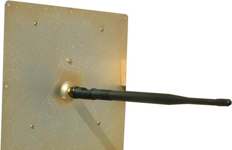
RY9SK8900
May 20, 2012SkySite Voice Repeater
Equipment Class
AMP - Amplifier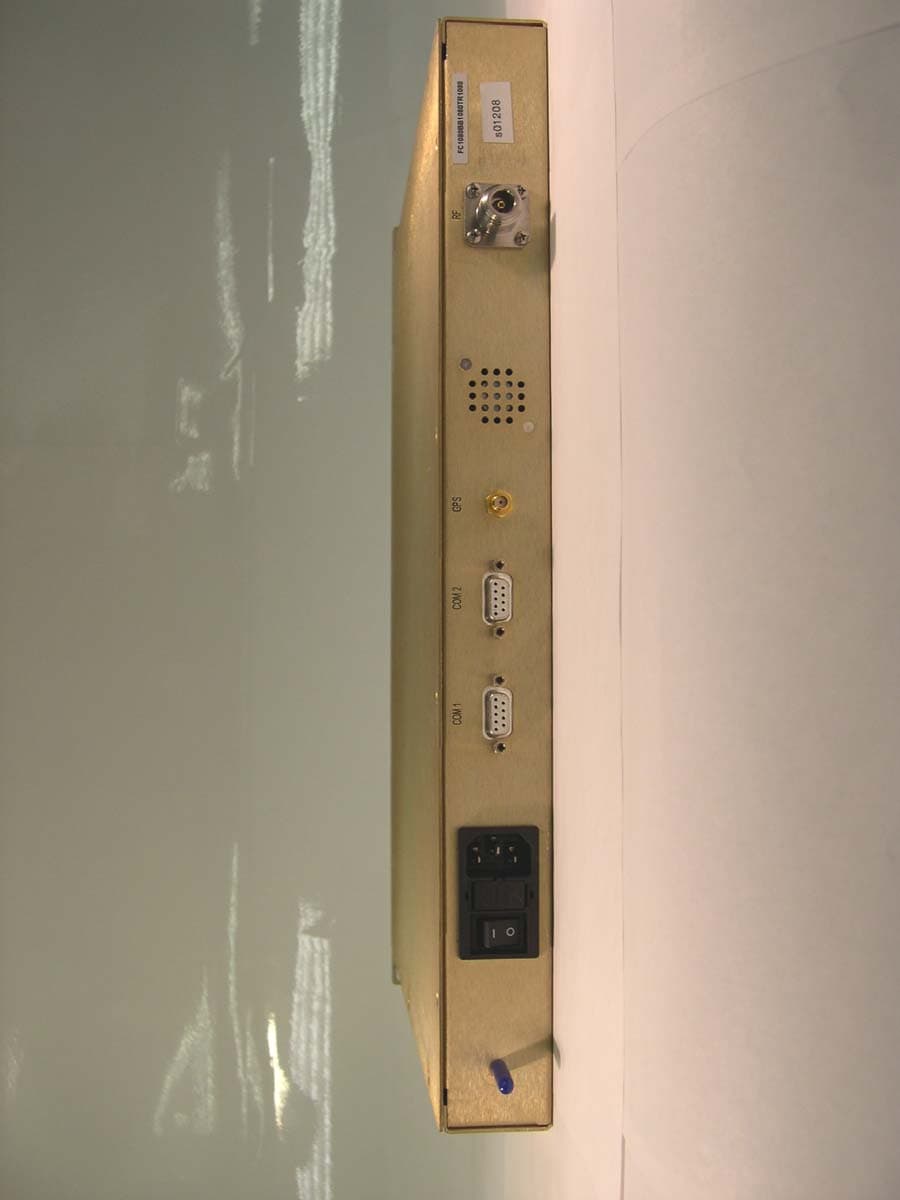
RY9GST900
Apr 19, 2004Narrow Band PCS
Equipment Class
PCB - PCS Licensed Transmitter