RY9SKS900MK2Narrowband PCS, Multi-Protocol SkySite
Space Data Corporation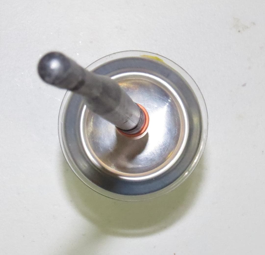
Click to zoom
Application Details
- Equipment Class
- PCB - PCS Licensed Transmitter
- Date of Grant
- May 27, 2013
- Application Purpose
- Original Equipment
- Date of Application
- May 27, 2013
- Equipment Note
- Narrowband PCS, Multi-Protocol SkySite
- Frequency Range
- 940.00000000 - 941.00000000
- Company
- Space Data Corporation
- Country
- United States
Documents & Files
Document Text
Text extracted from the exhibit documents filed with the FCC. Open a document above to read the original.
Users Manual
- 1 - Space Data Corporation Confidential and proprietary information ________________________________________________________________________ Space Data Corporation SkySite System Operators Instructions Model SKS-900-MK2 SkySite and Model GST-900 Ground Station Space Data Corporation 2535 W. Fairview St. Suite 101 Chandler, Arizona 85224 April 2013 - 2 - Space Data Corporation Confidential and proprietary information 1.0 Introduction The Space Data Corporation SkySite network is designed to provide narrowband wireless paging, Machine-to-Machine (M2M), and Push-to-Talk voices services to remote areas that are not practically serviced by traditional terrestrial communication towers. This narrowband wireless coverage is accomplished by mounting the functional equivalent of a communications tower on a high altitude weather balloon thereby overcoming service limitations. The SkySite Network consists of 5 subsystems listed below. 1. SkySite Platform (either SkySite 900 Mark 1 or SkySite 900 Mark 2 models) 2. Launch Facilities 3. Ground Station 4. Network Control Center. 5. SkySite Control Center Figure 1.1: The SkySite Network This document is a summary of the procedures used to deploy and operate the SkySite network. All equipment shown is manufactured, operated and serviced by Space Data Corporation and is therefore meant for internal use only. - 3 - Space Data Corporation Confidential and proprietary information 2.0 Pre-Launch Control Center operations are managed through the use of several Space Data Corp. proprietary software applications. These client applications run from EPS (Engineering Programming Software) server: GST (Ground Station). The GST maintains the communication link from the ground to the SkySite. The GST also monitors and controls ground station functions such as antenna auto-tracking, Receive signal strength, TX and RX power levels and frequency correction. SkySite client. Monitors SkySite performance such as TX and RX power levels, GPS position, battery current and voltage, and AH consumed. Vent ballast controls and accumulated values release command. Mapping client. This application utilizes the GPS coordinates sent from the SkySite and superimposes it on mapping software. Terrain and population density are easily determined from this screen and is used to plan recovery of the payload. The mapping client also has predictive capability. Using wind speed and direction information obtained on ascent, the software can predict where a SkySite will land if release at that moment from the balloon and descends using its parachute. 2.1 Pre-Flight Client Preparation Start all GST (Ground Station Transceiver) and SKS (SkySite) clients. Both software applications should connect to the EPS (Engineering Programming Software) server. During operation each client should appear as shown in Figures 2.1 and 2.2 below. Figure 2.1 – GST Client Screen - 4 - Space Data Corporation Confidential and proprietary information Figure 2.2 – SKS Client Screen Determine the type of antenna used by the Ground station in operation. There are only two types of antennas used for the Ground Station: 1. Omi-directional antenna (Max. Gain of 3dBi) 2. Yagi antenna (Max. Gain of 10dBi) Determine the type of antenna used by the SkySite (SKS900 or SKS900MK2). There are only two types of antennas used for the SkySite: 1. Low Gain Antenna (Antenna 1) (Max. Gain of 3dBi) 2. High Gain Co-Linear Array Antenna (Antenna 2) (Max. Gain of 9.22 dBi) Caution: In order to comply with FCC Part 24 and RF (Radio Frequency) exposure limits of this product the maximum GST ERP (Effective Radiated Power) must not exceed 7 Watts into a dipole antenna a gain of 2.15 dbi (40.6 dBm). When Antenna 2 is used with the SkySite, the transmit power at 901 MHz must not exceed 31 dBm. This power level when combined with the gain of Antenna 2 is below the 7 Watt ERP limit of FCC Part 24 for 901 MHz transmitters. - 5 - Space Data Corporation Confidential and proprietary information Transmit power levels are shown in the bottom left corner of the GST client in the “TX GLP HPA STATUS” box. This value does not include the directional gain of the antenna. Therefore the maximum permissible power levels into the antenna as are as follows: 1. Using the Omni-directional antenna the maximum power is 35dBm. 2. Using the high gain Yagi antenna the maximum power is 28dBm. Transmit power levels are shown in the bottom left corner of the SkySite client in the “TX GLP HPA STATUS” box. This value does not include the directional gain of the antenna. Therefore the maximum permissible power levels into the antenna as are as follows: 3. Using Antenna 1 (low gain) the maximum power is 35dBm. 4. Using Antenna 2 (co-linear dipole) the maximum power is 31dBm. Start all GST and SKS clients. Ensure that GST clients connect to EPS server. On GST Client open the GLP RSSI and GPS screens On the SKS Client open the following screens: GPS. GLP RSSI. Altitude vs. heading graphs. Altitude vs. Horizontal speed. Vertical speed graph. Check Antenna Control: Disable tracking Ensure client is in “remote tracking” mode. For each GST client slew antenna in azimuth and elevation. Point antenna toward launch site at 0 degrees elevation. Start GPS client on mapping PC and ensure it connects to EPS server. The GPS client started must correspond to the GST that will be used to control the payload. - 6 - Space Data Corporation Confidential and proprietary information Figure 2.3 – Mapping Client Screen Start predictor software on mapping PC Start Delorme payload and predictor programs on mapping PC. Start Delorme payload and predictor programs on mapping PC. The mapping client should look like Figure 2.3 as shown above. 3.0 Balloon Fill Steps 3.1 Initial Preparation Arrive 1 hours before scheduled launch Obtain pre-flight checklist Turn on handheld radio for communication with local airport traffic (if applicable) Verify channel and that comms are operating - 7 - Sp…
Text truncated - open the document above for the full version.
Cover Letter(s)
www.spacedata.net | 2535 W Fairview St., Ste.101, Chandler, AZ 85224 | P.O. Box 1866, Chandler, AZ 85244 | Tel 480.722.2100 Fax 480.403.0021 29 March 2013 Federal Communications Commission Authorization & Evaluation Division 7345 Oakland Mills Road Columbia, Maryland 21046 Re: Agent Authorization To Whom It May Concern: This letter will authorize Compliance Testing LLC to act as our Agent in all FCC matters. This appointment is effective until otherwise notified by us. This is to advise that we are in full compliance with the Anti-Drug Abuse Act. The Applicant is not subject to a denial of federal benefits pursuant to Section 5301 of the Anti-Drug Abuse Act of 1988, 21 USC 862, and no party to the application is subject to a denial of federal benefits pursuant to that section. Space Data Corporation Jerry Quenneville Vice President, Business Development
Cover Letter(s)
www.spacedata.net | 2535 W Fairview St., Ste.101, Chandler, AZ 85224 | P.O. Box 1866, Chandler, AZ 85244 | Tel 480.722.2100 Fax 480.403.0021 March 29, 2013 Federal Communications Commission EQUIPMENT APPROVAL SERVICES P.O. Box 358315 Pittsburgh, PA 15251-5313 ATTN: Authorization & Evaluation Division PER: 47 CFR 0.457 and 0.459 RE: RY9SKS900MK2 Pursuant to Sections 0.457(d)(1)(ii) and 0.459 of the Commission’s Rules, the Applicant hereby requests confidential treatment of some of the information accompanying this Application as listed below. Specifically: Schematics Block diagrams Theory of Operation Parts lists Tune-up information These materials contain trade secrets and proprietary information not customarily released to the public and the public disclosure of these matters might be harmful to the Applicant and provide unjustified benefits to its competitors. The Applicant understands that pursuant to Rule 0.457(d)(1)(ii) disclosure of this Application and all accompanying documentation will not be made before the date of the Grant for this Application. Please contact me if there is any information you might need. Sincerely, Space Data Corporation Jerry Quenneville Vice President, Business Development
External Photos
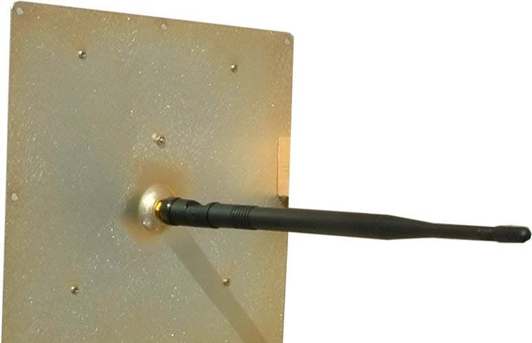
Applicant: Space Data Corporation Type ID: RY9SKS900MK2 EXHIBIT 3 SHEET 1 OF 6 External Photos The following photographs are attached Exhibit 1. Top View 3A 2. Side View Antenna 1 3B 3. Side View Antenna 2 3C 4. Bottom View Antenna 1 3D 5. Bottom View Antenna 2 3E Applicant: Space Data Corporation Type ID: RY9SKS900MK2 EXHIBIT 3 SHEET 2 OF 6 Top View Exhibit 3A Applicant: Space Data Corporation Type ID: RY9SKS900MK2 EXHIBIT 3 SHEET 3 OF 6 Side View Antenna 1 Exhibit 3B Applicant: Space Data Corporation Type ID: RY9SKS900MK2 EXHIBIT 3 SHEET 4 OF 6 Side View Antenna 2 Exhibit 3C Applicant: Space Data Corporation Type ID: RY9SKS900MK2 EXHIBIT 3 SHEET 5 OF 6 Bottom View Antenna 1 Exhibit 3D Applicant: Space Data Corporation Type ID: RY9SKS900MK2 EXHIBIT 3 SHEET 6 OF 6 Bottom View Antenna 2 Exhibit 3E
ID Label/Location Info
Applicant: Space Data Corp. FCC ID: RY9SKS900MK2 FCC ID: RY9SKS900MK2 Model: SKS-900-MK2 This device complies with Part 15 of the FCC Rules. Operation is subject to the following two conditions: 1.) This device may not cause harmful interference, and 2.) This device must accept any interference that may be received, including interference that may cause undesired operation Made in U.S.A. FCC ID and Compliance Statement label
ID Label/Location Info
Applicant: Space Data Corp. FCC ID: RY9SKS900MK2 FCC Label placement on SKS-900-MK 2 product
Internal Photos
Applicant: Space Data Corp. FCC ID: RY9SKS900MK2 FCC Label placement on SKS-900-MK 2 product
Operational Description
- 1 - Space Data Corporation Confidential and proprietary information ________________________________________________________________________ Space Data Corporation 2535 W. Fairview St. Suite 101 Chandler, Arizona 85224 Space Data Corporation SkySite MK2 Co-Linear Antenna Specification Antenna 2 for the SKS900MK2 consists six element co-linear dipole array with fixed phasing between the elements to provide a down tilted pattern such that the power level on the ground is approximately uniform after adjusting for free space loss when the SKS900MK2 is transmitting at an altitude of 26 km above the ground. The antenna is implemented with properly shaped metal foil elements laminated in a dielectric and held straight within a thin-walled polycarbonate tube. Frequency: 900 – 941 MHz Max Power: 10 Watts Gain: 9.11 dBi at 900 MHz 9.22 dBi at 941 MHz Downtilt: 3.5 degrees at 900 MHz 7.8 degrees at 940 MHz 3 dB Beamwidth: 9.7 degrees at 900 MHz 8.8 degrees at 941 MHz Return Loss: 25 dB at 900 MHz 22 dB at 910 MHz 22 dB at 920 MHz 24 dB at 930 MHz 17 dB at 941 MHz - 2 - Space Data Corporation Confidential and proprietary information Antenna 2 Vertical Pattern at 900 MHz Antenna 2 Pattern at 941 MHz Note: the radiaitons patterns in the horixontal plan are axisyemtric about the vertical axis of Antenna 2 (e.g. circular)
Operational Description
- 1 - Space Data Corporation Confidential and proprietary information ________________________________________________________________________ Space Data Corporation SkySite MK2 15.247 Antenna Specification The 15.247 Antenna for the SKS900MK2 consists of a length of 24 AWG insulated multi-strand wire ¼ wave length (12 cm long) Gain: 0 dBi Pattern: Spherical Frequency: 902 – 928 MHz Space Data Corporation 2535 W. Fairview St. Suite 101 Chandler, Arizona 85224b
Test Report
p1330009_FCC_Part 24_Rev 2.0 Page 1 of 52 Test Report Prepared for: Space Data Corporation Model: SKS-900-MK2 Description: Narrowband PCS, Multi-Protocol SkySite FCC ID: RY9SKS900MK2 To FCC Part 24 Date of Issue: April 9, 2013 On the behalf of the applicant: Space Data Corporation 2535 W. Fairview Street Suite 101 Chandler, AZ 85224 Attention of: Jerry Knoblach, Chairman / CEO Ph: (480)722-2100 E-Mail: knoblach@spacedata Prepared By Compliance Testing, LLC 3356 N San Marcos Pl, Suite 107 Chandler, AZ 85225-7176 (866) 311-3268 phone / (480) 926-3598 fax www.compliancetesting.com Project No: p1330009 Greg Corbin Project Test Engineer This report may not be reproduced, except in full, without written permission from Compliance Testing. All results contained herein relate only to the sample tested. p1330009_FCC_Part 24_Rev 2.0 Page 2 of 52 Test Report Revision History Revision Date Revised By Reason for Revision 1.0 April 9, 2013 Greg Corbin Original Document 2.0 May 2, 2013 Greg Corbin Removed reference to an obsolete test procedure on page 6. Removed antenna requirements statement from page 8. Clarified spectrum analyzer settings and added a graph to page 10. Clarified statement at end of the test data on Page 18 p1330009_FCC_Part 24_Rev 2.0 Page 3 of 52 Table of Contents Description Page Standard Test Conditions and Engineering Practices 6 Test Result Summary 9 Carrier Output Power (Conducted) 10 Conducted Spurious Emissions 12 Field Strength of Spurious Radiation 16 Emission Masks (Occupied Bandwidth) 19 Frequency Stability (Temperature Variation) 44 Necessary Bandwidth Calculations 45 Test Equipment Utilized 52 p1330009_FCC_Part 24_Rev 2.0 Page 4 of 52 ILAC / A2LA Compliance Testing, LLC, has been accredited in accordance with the recognized International Standard ISO/IEC 17025:2005. This accreditation demonstrates technical competence for a defined scope and the operation of a laboratory quality management system (refer joint ISO-ILAC-IAF Communiqué dated January 2009) The tests results contained within this test report all fall within our scope of accreditation, unless noted below. Please refer to http://www.compliancetesting.com/labscope.html for current scope of accreditation. Testing Certificate Number: 2152.01 FCC OATS Reg, #933597 IC Reg. #2044A-1 Non-accredited tests contained in this report: N/A p1330009_FCC_Part 24_Rev 2.0 Page 5 of 52 The Applicant has been cautioned as to the following 15.21: Information to the User The user’s manual or instruction manual for an intentional radiator shall caution the user that changes or modifications not expressly approved by the party responsible for compliance could void the user’s authority to operate the equipment. 15.27(a): Special Accessories Equipment marketed to a consumer must be capable of complying with the necessary regulations in the configuration in which the equipment is marketed. Where special accessories, such as shielded cables and/or special connectors are required to enable an unintentional or intentional radiator to comply with the emission limits in this part, the equipment must be marketed with, i.e. shipped and sold with, those special accessories. However, in lieu of shipping or packaging the special accessories with the unintentional or intentional radiator, the responsible party may employ other methods of ensuring that the special accessories are provided to the consumer, without an additional charge. Information detailing any alternative method used to supply the special accessories for a grant of equipment authorization or retained in the verification records, as appropriate. The party responsible for the equipment, as detailed in § 2.909 of this chapter, shall ensure that these special accessories are provided with the equipment. The instruction manual for such devices shall include appropriate instructions on the first page of text concerned with the installation of the device that these special accessories must be used with the device. It is the responsibility of the user to use the needed special accessories supplied with the equipment. p1330009_FCC_Part 24_Rev 2.0 Page 6 of 52 Test and Measurement Data All tests and measurement data shown were performed in accordance with FCC Rules and Regulations, Volume II, Part 2, Sub-part J, Sections 2.947, 2.1033(c), 2.1041, 2.1046, 2.1047, 2.1079, 2.1051, 2.1053, 2.1055, 2.1057, the sections of Part 24 as noted in the test summary table. Standard Test Conditions and Engineering Practices Except as noted herein, the following conditions and procedures were observed during the testing. In accordance with ANSI/C63.4-2009, and unless otherwise indicated in the specific measurement results, the ambient temperature of the actual EUT was maintained within the range of 10° to 40°C (50° to 104°F) unless the particular equipment requirements specify testing over a different temperature range. Also, unless otherwise indicated, the humidity levels were in the range of 10% to 90% relative humidity. Environmental Conditions Temp (ºC) Humidity (%) Pressure (mbar) 23.3 – 28.0 17.5 – 27.7 950.7 – 970.8 Measurement results, unless otherwise noted, are worst-case measurements. EUT Description Model: SKS-900-MK2 Description: Narrowband PCS, Multi-Protocol SkySite Firmware: Code revision for the AS_1947 board: V1.00 Code revision for the AS_1953 board: V1.00 Additional Information The EUT is a transceiver that mounts on a weather balloon to provide narrowband communication services to remote areas. The SkySite ® transceiver receives radio FSK encoded digital packets from a ground station or subscriber devices, converts these FSK signals into digital data, corrects errors, and retransmits the corrected data to the intended ground station or subscriber device. Refer to Table 1 for the list of all the Emission Types that are available with this EUT. The EUT operates in the following 3 frequency bands, 901 – 902 MHz, 930 – 931 MHz, 940 – 941 MHz. The EUT was tested at the center of each band…
Text truncated - open the document above for the full version.
Test Report
p1330009_FCC_Part 1.1310_Rev 2.0 Page 1 of 4 Test Report Prepared for: Space Data Corporation Model: SKS-900-MK2 Description: Narrowband PCS, Multi-Protocol SkySite FCC ID: RY9SKS900MK2 To FCC Part 1.1310 Date of Issue: April 16, 2013 On the behalf of the applicant: Space Data Corporation 2535 W. Fairview Street Suite 101 Chandler, AZ 85224 Attention of: Jerry Knoblach, Chairman / CEO Ph: (480)722-2100 E-Mail: [email protected] Prepared By Compliance Testing, LLC 3356 N San Marcos Pl, Suite 107 Chandler, AZ 85225-7176 (866) 311-3268 phone / (480) 926-3598 fax www.compliancetesting.com Project No: p1330009 Greg Corbin Project Test Engineer This report may not be reproduced, except in full, without written permission from Compliance Testing All results contained herein relate only to the sample tested p1330009_FCC_Part 1.1310_Rev 2.0 Page 2 of 4 Test Report Revision History Revision Date Revised By Reason for Revision 1.0 April 16, 2013 Greg Corbin Original Document 2.0 May 9, 2013 Greg Corbin Updated Antenna gain information based on new data from the manufacture. p1330009_FCC_Part 1.1310_Rev 2.0 Page 3 of 4 ILAC / A2LA Compliance Testing, LLC, has been accredited in accordance with the recognized International Standard ISO/IEC 17025:2005. This accreditation demonstrates technical competence for a defined scope and the operation of a laboratory quality management system (refer joint ISO-ILAC-IAF Communiqué dated January 2009) The tests results contained within this test report all fall within our scope of accreditation, unless below Please refer to http://www.compliancetesting.com/labscope.html for current scope of accreditation. Testing Certificate Number: 2152.01 FCC OATS Reg, #933597 IC Reg. #2044A-1 Non-accredited tests contained in this report: N/A p1330009_FCC_Part 1.1310_Rev 2.0 Page 4 of 4 Description The SKS-900-MK2 contains 2 transmitters that are tethered to a weather balloon. 1 transmitter provides narrowband communication services to remote areas on the ground. The 2nd transmitter is used to transmit to the balloon vent and the ballast assembly which are up to 100 feet away from the SKS-900-MK2. The EUT has 2 co-located transmitters. The Power Density was calculated for each transmitter and summed together for the final Power Density calculation. The SKS-900-MK2 transmits in the unlicensed ISM band on a single channel at 915 MHz at an effective radiated power of less than 10 dBm. This wireless channel is used to transmit to the balloon vent and the ballast assembly which are up to 100 feet away from the SKS-900-MK2 This is a mobile device used in Controlled Exposure environment. Limits - Controlled Exposure 47 CFR 1.1310 Table 1, (A) 0.3-3.0 MHz: Limit [mW/cm²] = 100 3.0-30 MHz: Limit [mW/cm²] = (900/f²) 30-300 MHz: Limit [mW/cm²] = 1.0 300-1500 MHz: Limit [mW/cm²] = f/300 1500-100,000 MHz Limit [mW/cm²] = 5 Test Frequencies, MHz 915 Power, Conducted, mW (P) 8.71 Antenna Gain Isotropic 0 dBi Antenna Gain Numeric (G) 1 Antenna Type 3.5 inch piece of wire, mfr states that it is a ¼ wavelength at 915 MHz Distance (R) 20 cm Test Frequencies, MHz 901 Power, Conducted, mW (P) 631 Antenna Gain Isotropic 9.2 dBi Antenna Gain Numeric (G) 8.32 Antenna Type Co-Linear Dipole Array high gain antenna, note: that the mfr states in the user manual that the transmit power is limited to 28 dBm (631 mw) when using the Co-Linear Dipole Array antenna Distance (R) 20 cm Co-located Power Density Calculations Formula = S = PG / 4πR² Power Density (S) = 1.04 mW/cm² Limit = 3.00 mW/cm² The Co-located Power Density is below the Limit. The SAR measurement is not necessary. END OF TEST REPORT
Test Setup Photos
Page 1 of 10 Test Setup Photos: Space Data Corp FCC ID: RY9SKS900MK2 Part 24 Conducted RF Conducted RF Page 2 of 10 Conducted RF Conducted RF Page 3 of 10 Radiated 30-1000 MHz Page 4 of 10 Radiated 30-1000 MHz Page 5 of 10 Radiated 30-1000 MHz Radiated 30-1000 MHz Page 6 of 10 Radiated 30-1000 MHz Radiated 30-1000 MHz Page 7 of 10 Radiated above 1 GHz Radiated above 1 GHz Page 8 of 10 Radiated above 1 GHz Page 9 of 10 Space Data user Interface GUI Temp Stability 24D Transmitter Page 10 of 10 Temp Stability 24D Transmitter
Contact Information
Applicant
Gerard J. Quenneville(Vice President, Business Development)
Technical Specifications
| # | Rule Parts | Frequency Range | Power Output | Emission | Tolerance |
|---|---|---|---|---|---|
| 69 | 24D | 940 MHz - 941 MHz | 2.387 W | 32K0F1D | 1 ppm |
Other Applications from Space Data Corporation
RY9SK8900
May 20, 2012SkySite Voice Repeater
Equipment Class
AMP - Amplifier
RY9GST900
Apr 19, 2004Narrow Band PCS
Equipment Class
PCB - PCS Licensed Transmitter
RY9SKS900
Apr 14, 2004Narrow Band PCS
Equipment Class
PCB - PCS Licensed Transmitter