RYLKN998Wireless Keyboard
DynaPoint (Dong Guan) Inc.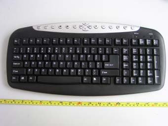
Click to zoom
Application Details
- Equipment Class
- DXX - Part 15 Low Power Communication Device Transmitter
- Date of Grant
- Nov 14, 2005
- Application Purpose
- Original Equipment
- Date of Application
- Nov 14, 2005
- Equipment Note
- Wireless Keyboard
- Frequency Range
- 27.14500000 - 27.14500000
- Company
- DynaPoint (Dong Guan) Inc.
- Country
- China
Documents & Files
Document Text
Text extracted from the exhibit documents filed with the FCC. Open a document above to read the original.
Users Manual
KN998 User’s Manual Introduction: This keyboard/optical mouse set is a wireless input device with 27Mhz radio frequency. It is plug & play with Windows Me/2000/XP, without the need of any software installation. If you did install any software for your previous keyboard or mouse, please remove the mouse driver before use this new device. This wireless keyboard/ optical mouse set consists of 3 parts, namely the keyboard, the optical mouse, and the receiver(see figure) System Requirement: IBM PC compatibles PS/2 ports for mouse and for keyboard Microsoft Windows Me/2000 and XP Install the Batter ies: The wireless mouse uses two AA batteries, and the keyboard uses two AA batteries.(For the best performance, please use only alkaline batteries)(see figure) 1. Open the battery compartment cover under the mouse. 2. Place two AA batteries inside the compartment 3. Close the battery compartment cover 4. Open the battery cover on the back of the keyboard 5. Insert two AA batteries, and the close the battery cover Connect The Receiver: RF wireless keyboard/optical mouse uses digital radio technology to communicate. It transmits radio frequency signals which are picked by the receiver, then passed to the computer. The receiver is connected to the computer’s PS/2 ports via a cable. Connect the green connector to the computer’s mouse port, and plug the purple connector to the keyboard port. Gaution: 1. Turn off the computer before connecting the receiver to your computer 2. For the best performance, place the receiver at least 20cm(8 inches) away from computer, monitor, and other devices which will cause radio interference. 3. Working on metallic surface will reduce the RF performance. Avoid placing the receiver on metallic surface. 4. Plug or unplug cable from the computer’s PS/2 ports improperly can cause damage to the PS/2 ports and to the computer. Set The ID Code After install the batteries and connect the receiver to computer, turn on your computer and follow the procedures as below to set the ID Code. There is an ID button on the Bottom of the Mouse, one on the Front of the keyboard, and another one on the front side of the Receiver.(see figure) 1. Press the ID Button on Receiver, then press the ID Button on Mouse, and then press the ID button on Keyboard. The ID code will be set automatically. The process of pressing these 3 buttons must be completed within 5 seconds. 2. After above process, the Receiver LED will blink, when you move the mouse, or type on the keyboard. This means that the keyboard and the mouse do communicate with the receiver successfully. 3. If you can not see the blinking LED when move the mouse or type on the keyboard, the keyboard/mouse can not work properly. Please re-install the batteries and retry the above set up process. Use The Mouse: After successful installation, the mouse can work well with Windows95/98/Me/2000/and XP, without the need of software driver. The mouse comes with a scrolling wheel, which can function either as a wheel or as a button. (see figure) 1. To scroll up, move the wheel forward; to scroll down, move the wheel backward. 2. To use the wheel like a standard mouse middle button, simply click(press down)the wheel button. Use The Keyboard: After successful installation, the keyboard can work well with Windows Me/2000/XT, without the need of software driver. The keyboard is a 107/5-key model; it comes with 15 hot keys to enable one touch access to multimedia/ internet functions.(see figure) 1. Play/Pause: Play or Pause audio or video CD 2. Volume Down: Decrease the volume 3. Volume Up: Increase the volume 4. Mute: Make voiceless while playing CD 5. Previous: Go to the Previous CD Track 6. Next: Changes to the next media track. 7. Stop: Stop downloading the content of the web page 8. Internet: Open browser in Internet Explorer 9. E-mail: Open mail folder in Outlook Express 10. Search: Launch your web search function. 11. Backward: Back to last web page when viewing the internet 12. Forward: Go to next web page when viewing the internet 13. Sleep: Turn computer into sleep mode 14. Wake up: The computer from sleep mode. 15. Power: Turn on/off the computer. Warnings: When the low battery indicator is flash means the power is not enough, you’d better replace the batteries Trouble Shooting: 1. If your keyboard/mouse can not work after installation, please check followings: a).make sure you have connected the receiver correctly to the computer. The receiver’s connectors have been properly plugged onto computer’s PS/2 ports. b).Make sure you have inserted the batteries correctly. c).Make sure you have set the ID codes properly, as stated above. e).For better performance, place the receiver at least 20 cm(8 inches)away from computer, monitor, or other devices which will cause radio interference. Avoid placing the receiver on metallic surface. f).If without any interference(for example the other computer peripherals), the working distance of the keyboard/mouse-i. e. the distance between the keyboard/mouse and the receiver, is about 5 feet. 2. If the mouse cursor does not move properly, or the key-in data does not prompt up on the screen, please check following: a).Check the position lf your receiver. Maybe the receiver is too far away. b).Check the large metal devices, such as microwave, electric stove, television, hair dryer....,which may interfere the receiver’s radio reception. c).Check the status of the batteries. The batteries may be near dead. If the keyboard/mouse does not work after some time of usage, please replace the batteries to see if it can solve the problem. Warning: Changes or modifications to this unit not expressly approved by the party responsible for compliance will void the user’s authority to operate the equipment. Any change to the equipment will void FCC grant. This equipment has been tested and found to comply with the limits for a Class B digital device, pursuant to part 15 of the FCC Rules. These limits are designed to provide reaso…
Text truncated - open the document above for the full version.
Block Diagram
KN998 Block Diagram 27MHZ MOUSE RECEIVER MCU PC EEPRO M 27MHZ KEYBOARD RECEIVER PCB ANT PCB ANT KEYBOARD MCU MOUSE MCU BETTERY 3V BETTERY 3V rising 3V SENS or Led
External Photos
External Photos FCC ID: RYLKN998
ID Label/Location Info
ID Label Label FCC ID: RYLKN998
ID Label/Location Info
ID Label/Location Label Location Information Specifications: Text is Black or white in color and is left justified. Labels are printed in indelible ink on permanent adhesive backing or silk-screened onto the EUT or shall be affixed at a conspicuous location on the EUT. Refer to the below arrow. FCC ID: RYLKN998
Internal Photos
Internal Photos
Operational Description
KN998 Circuitry Description The MA6231 is a single chip keyboard transmitter. It is developed to achieve a better performance/cost ration for wireless office keyboard system. The MA6231 supports 176 (22*8) keys and 3 rolling wheels which are either IR/PT or mechanical device. The MA6231 operates using dual RF channels and PS/2 office keyboard device. The MA6231 senses the key press from keyboard and the rolling wheels motion from keyboard device then send their data via RF. Furthermore, the MA6231 has a DC/DC embedded. *Low power CMOS device technology *Support office keyboard (22 * 8 keys) *2 RF channels are supported *3 build-in rolling wheels controller (both mechanical and photo device are supported) *Auto sleep mode *Phantom key detection *32.768KHz clock rate (low power consumption) *Build-in RF oscillator, modulator and power amplifier * Low power design in standby mode for keyboard and mouse *4k bps Baud rate in air. *ID change solution to resist the interference from the same device *DC/DC embedded *Low Power Detection
Parts List/Tune Up Info
BOM Sequence number Materiel code Materiel apellation Spec model Unit Dosage Location mark 1 A0.021.00010 CAPACITOR 100UF/6.3V 5*5 PCS 2.00 C8,9 2 A0.040.00048 ID Switch 6*6*9mm H=9MM 1A 125V DIP 130g H:4MM PCS 1.00 SW1 3 A0.052.00051 LED B3024T4 Red 3MM DIP PCS 1.0000 LED1 5 A0.082.00028 CRYSTAL 32.768KHZ 2P 3*8 PCS 1.0000 Y1 6 A0.082.00032 CRYSTAL 27.142MHz 2P 49S PCS 1.0000 Y2 7 A0.100.00005 INDUCTOR 1.8UH 1/8W ±5% PCS 1.00 L3 8 A0.100.00007 INDUCTOR 100UH 1/4W ±5% PCS 1.00 L1 9 B0.120.00091 LED bushing L=3.8MM ф 3 (KN558) pcs 1.0000 D1 10 A0.011.00011 RES 0 Ω 0603 ±5% PCS 1.00 J6 11 A0.011.00014 RES 4.7M 0603 ±5% PCS 1.00 R1 12 A0.011.00015 RES 100K 0603 ±5% PCS 1.00 R3 13 A0.011.00020 RES 220K 0603 ±5% PCS 1.00 R2 14 A0.011.00031 RES 560 Ω 0603 ±5% PCS 1.00 R7 15 A0.011.00064 RES 1.2M 0603 ±5% PCS 1.00 R6 16 A0.011.00065 RES 680K 0603 ±5% PCS 1.00 R9 17 A0.023.00002 CAP 104P/50V ±20% 0603 PCS 3.00 C11,12,17 18 A0.023.00006 CAP 47P/50V ±5% 0603 PCS 3.00 C1,2,14 19 A0.023.00009 CAP 22P/50V ±5% 0603 PCS 2.00 C3,15 20 A0.023.00018 CAP 33P/50V ±5% 0603 PCS 1.00 C5 21 A0.023.00041 CAP 39p/50V ±5% 0603 PCS 1.00 C4 22 A0.023.00055 CAP 12P/50V ±5% 0603 PCS 1.00 C7 23 A0.031.00038 IC MA6121 SMD 64P PCS 1.0000 U1 24 A0.051.00008 DIODE 5819 SMD 2P mini 3.6*1.6MM PCS 1.0000 D1 25 A0.070.00335-A0 PCB DY00718 FR-4 H:1.6MM REV:A0 PCS 1.0000 Page 1
Schematics
1 2 34 ABCD 4 3 2 1 D CBA Title Nu mb er R e vi si o n Size A4 Da te: 5 -Oct -2005 She et of File: F:\KN998\KN998 最终修改版 .DDB Drawn By: LBUT 10 MBUT 9 RBUT 8 OSC 2 7 OSC 1 6 BBUT 5 FBUT 4 VDD 3 COL[0] 2 COL[1] 1 TXCB 11 OR F1 12 OR F2 13 RFOUT 14 RFCT L 15 TEST 17 X1 IN 18 X2 IN 19 Y1 IN 20 Y2 IN 21 Z1IN 22 Z2IN 23 XR E ST 24 W1IN 25 W2IN 26 XIR 27 SVDIN 28 VSS 29 ROW[7] 30 ROW[6] 31 ROW[5] 32 TXD 16 ROW[4] 33 ROW[3] 34 ROW[2] 35 ROW[1] 36 ROW[0] 37 P2[6 ] 38 R1 IN 39 R2 IN 40 L1 IN 41 L2 IN 42 TURBO 43 VSSS 44 VL 45 DC VR 46 COL[19] 47 COL[18] 48 COL[17] 49 COL[16] 50 COL[15] 51 COL[14] 52 COL[13] 53 COL[12] 54 COL[11] 55 COL[10] 56 COL[9] 57 COL[8] 58 COL[7] 59 COL[6] 60 COL[5] 61 COL[4] 62 COL[3] 63 COL[2] 64 U1 MA62 31 COL0COL1 COL2 COL3 COL4 COL5 COL6 COL7 COL8 COL9 COL10 COL11 COL12 COL13 COL14 COL15 COL16 COL17 COL18COL19 COL0 COL1 COL2 COL3 COL4 COL5 COL6 COL7 COL8 COL9 COL10 COL11 COL12 COL13 COL14 COL15 COL16 COL17 VDD R14.7M Y13 2. 7 68 KHZ C147PC247P SW1SW-ID Y227.142MHZ C3 20P C433P C533PF C6OPE N C710P ROW0ROW1ROW2ROW3ROW4 ROW5 ROW6 ROW7 BAT C8 1 00UF C11 104 L1 D1 5819 R2220KR3100k C12104 C9100UF VDD 1 2 3 4 5 6 7 8 9 10 11 12 13 14 15 16 17 18 19 20 21 22 23 24 25 26 CON1CONP-2620 ROW0 ROW1 ROW2 ROW3 ROW4 ROW5 ROW6 ROW7 R61.2M R9680K L31.8UH C1 447P C1522P BAT LD1LED R7560R VDD C1 61p BT11.5*2 MA6121\RF\KN998\SCH C1 0104 DCVR VL SWID X_LED R1610R C13104 C17220UF J80R REV:B0 DY00718
Test Report
Note: The test report is specially limited to the above company and this particular sample only. It may not be duplicated without prior written consent of Bay Area Compliance Lab Corp. (ShenZhen). This report must not be used by the client to claim product certification, approval, or endorsement by NVLAP, NIST or any agency of the US Government. FCC PART 15.227 EMI MEASUREMENT AND TEST REPORT For Dyna Point (Dong Guan) Inc. The Sixth Industrial Park. Shangsha, South Area ChangAn, DongGuan, GuangDong, China 523880 FCC ID: RYLKN998 May 24, 2005 This Report Concerns: Original Report Equipment Type: Transmitter, wireless keyboard Test Engineer: Lisa Zhu Report No.: RSZ05051607 Test Date: May 20, 2005 Reviewed By: Chris Zeng Prepared By: Bay Area Compliance Lab Corp. (ShenZhen) 6/F, the 3rd Phase of WanLi Industrial Building, ShiHua Road, FuTian Free Trade Zone, ShenZhen, Guangdong 518038, P.R.China Tel: +86-755-33320018 Fax: +86-755-33320008 Dyna Point (Dong Guan) Inc. FCC ID: RYLKN998 Report # RSZ05051607 Page 2 of 11 FCC PART 15.227 Report TABLE OF CONTENTS GENERAL INFORMATION.......................................................................................................................................3 PRODUCT DESCRIPTION FOR EQUIPMENT UNDER TEST (EUT) ....................................................................................3 OBJECTIVE...................................................................................................................................................................3 RELATED SUBMITTAL(S)/GRANT(S).............................................................................................................................3 TEST METHODOLOGY..................................................................................................................................................3 TEST FACILITY.............................................................................................................................................................3 SYSTEM TEST CONFIGURATION ..........................................................................................................................4 JUSTIFICATION.............................................................................................................................................................4 EUT EXERCISE SOFTWARE..........................................................................................................................................4 SPECIAL ACCESSORIES.................................................................................................................................................4 EQUIPMENT MODIFICATIONS.......................................................................................................................................4 CONFIGURATION OF TEST SETUP.................................................................................................................................5 B LOCK D IAGRAM OF T EST S ETUP ................................................................................................................................5 SUMMARY OF TEST RESULTS...............................................................................................................................6 §15.203 - ANTENNA REQUIREMENT......................................................................................................................7 STANDARD APPLICABLE..............................................................................................................................................7 §15.205, §15.209, §15.227(A) - RADIATED EMISSIONS TEST ..............................................................................8 MEASUREMENT UNCERTAINTY....................................................................................................................................8 EUT SETUP..................................................................................................................................................................8 EMI TEST RECEIVER SETUP........................................................................................................................................8 TEST EQUIPMENT LIST AND DETAILS...........................................................................................................................8 TEST PROCEDURE...................................................................................................................... CORRECTED AMPLITUDE & MARGIN CALCULATION...................................................................................................9 TEST RESULTS SUMMARY............................................................................................................................................9 TEST DATA..................................................................................................................................................................9 DUTY CYCLE............................................................................................................................. §15.227(B) - OUT OF BAND EMISSION .................................................................................................................10 EMI TEST RECEIVER SETUP......................................................................................................................................10 TEST EQUIPMENT LIST AND DETAILS.........................................................................................................................10 TEST PROCEDURE......................................................................................................................................................10 TEST DATA................................................................................................................................................................10 Dyna Point (Dong Guan) Inc. FCC ID: RYLKN998 …
Text truncated - open the document above for the full version.
Test Setup Photos
Test Setup Photos Radiated Emission - Front View Radiated Emission - Rear View
Contact Information
Applicant
Kouni Chang(Engineering Manager)
Test Firm
Bay Area Compliance Laboratory Corp. (Shenzhen)John Chan
Technical Specifications
| # | Rule Parts | Frequency Range | Power Output |
|---|---|---|---|
| 1 | 15C | 27.145 MHz - 27.145 MHz | - |
Other Applications from DynaPoint (Dong Guan) Inc.
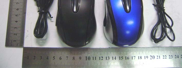
RYLH213E53USB
Oct 19, 2010MOUSE
Equipment Class
JBP - Part 15 Class B Computing Device Peripheral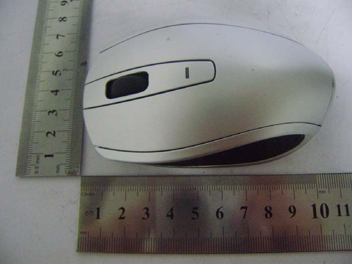
RYLH3LV6010USB
Sep 12, 20102.4G MOUSE
Equipment Class
DXX - Part 15 Low Power Communication Device Transmitter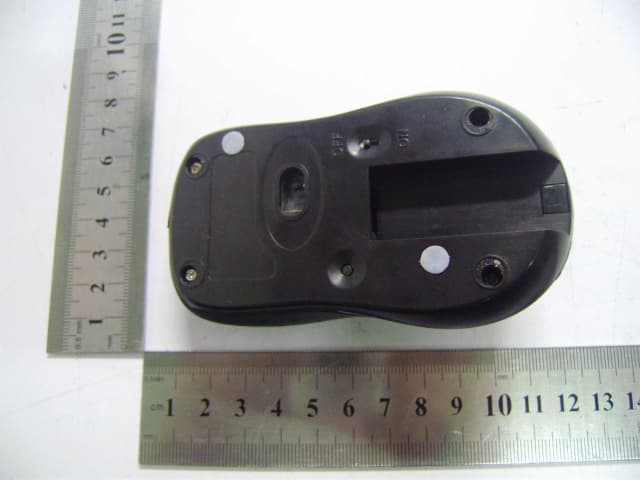
RYLH3PS5P10USB
Aug 31, 201027MHz MOUSE
Equipment Class
DXX - Part 15 Low Power Communication Device Transmitter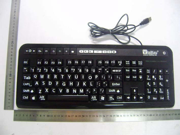
RYLKA558UH
Aug 29, 2010KEYBOARD
Equipment Class
JBP - Part 15 Class B Computing Device Peripheral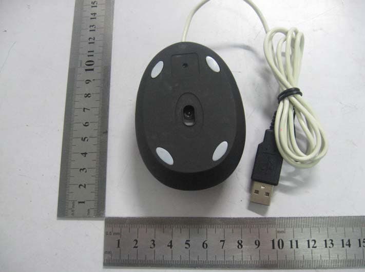
RYLH373E43USB
Jul 11, 2010MOUSE
Equipment Class
JBP - Part 15 Class B Computing Device Peripheral