RYZTEMPONITORClinic Patch Thermometer ( Temponitor )
K-jump Health Co.,Ltd.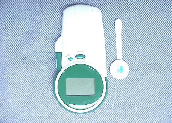
Click to zoom
Application Details
- Equipment Class
- DXX - Part 15 Low Power Communication Device Transmitter
- Date of Grant
- Apr 14, 2004
- Application Purpose
- Original Equipment
- Date of Application
- Apr 14, 2004
- Equipment Note
- Clinic Patch Thermometer ( Temponitor )
- Frequency Range
- 13.56000000 - 13.56000000
- Company
- K-jump Health Co.,Ltd.
- Country
- Taiwan
Documents & Files
Document Text
Text extracted from the exhibit documents filed with the FCC. Open a document above to read the original.
Users Manual
1 2 3 Clinic Patch Thermometer (Temponitor) Model KD-2100 Intended for UseThis device is intended to be used to monitor the body temperature by applyingthe temperature patch to body skin or axillary. Contents...............................................1Precaution............................................2About the device....................................2Battery installation/replacement.............3Setting the device..................................4Preparation before measurement............5Important information.............................6Start measurement.................................7 Memory reading.....................................8Using the flash light................................8Turn off the device..................................8 Maintenance..........................................9Error message......................................10Specification........................................ 11 USER INSTRUCTION 37.0 C 15:38 TIME Manufacturer : K-Jump Health Co., Ltd. th No. 56 Wu Kung 5 Rd.,Wu Ku Industrial Park,Taipei Hsien, Taiwan 248 FCC Interference StatementFCC ID : RYZTEMPONITOR This equipment has been tested and found to comply with the limits for a Class B digital device, pursuant to Part 15 of the FCC Rules. These limits are designed to provide reasonable protection against harmful interference in a residentialinstallation. This equipment generates, uses and can radiate radio frequency energy and, if not installed and used in accordance with the instructions, may cause harmful interference to radio communications. However, there is no guarantee that interference with not occur in a particular installation. If this equipment does not cause harmful interference to radio or TV reception, which can be determined by turning the equipment off and on, the user is encouraged totry to correct the interference by one or more of the following measures:- Reorient or relocated the receiving antenna. - Increase the separation between the equipment and receiver.- Connect the equipment into and outlet on a circuit different from that to which the receiver is connected.- Consult the dealer or an experienced radio/TV technician for help.Caution: To assure continued FCC complianceAny changes or modifications not expressly approved by the grantee of this device could bevoid the user's authority to operate the device. 37.0 C 15:38 TIME KD-2101 Temperature Reader On/Off Key Start Key Light Key LCD Display Memory Key Light Battery installation / replacement TemperatureUnit Low Battery Memory MEMORY 1. Remove battery cover by pulling thebattery cover. 2. Install/replace four new 1.5 V Size- AAAbatteries into the battery compartment. Note that be sure the batteries shouldhave the correct polarity. 3. Close the battery cover. Temperature Date/Time The LCD DATE (M/D) TIME Contents Precaution About the Device (2) About the Device (1) The Patch KD-PT01Under Arm Patch Transmission PartTransmission Part TemperatureSensor Transmission Part Temperature Sensor KD-PT02Body Skin Patch KD-PT03Ear Plug Patch Notice1. Use of this thermometer is not to be a substitute for consulting with a physician. 2. Person with pacemaker implemented should consult the doctor before usingthis device. 3. Intensive supervision is necessary when using this device on infant, children and compromised person. This device complies with Part 15 of the FCC Rules. Operation is subject to the following two conditions: (1)this device maynot cause harmful interference, and (2)thisdevice must accept any interference received, including interference that may cause undesired operation. Transmission Part Temperature Sensor 4 5 6 7 Setting the Device sensor Adhesive tape About the sensorThe sensors is constructed by two parts: transmitter and temperature sensor . The transmitter is used for inducing power as well as data transmission; the temperature sensor is used for body temperaturedetecting. Applying the Sensor For fixing the sensor, a dressing (or surgical) adhesive tape will be needed. A high quality tape without side-effect is recommended since long period (usually 24~48 hr)adhesion.1. Apply the sensor to ear canal, armpit or abdominal area below navel(depended on different types). 2. For armpit and body skin, fixing the sensor by medical adhesive tape(s). Besure the firmness. 3. Subject is allowed to dress cloth rather than naked. 4. For infant or baby, the patch under diaper will benefit the measurement result sincewarmer measurement environment. sensor Adhesive tape Preparation before Measurement Period for Heat Equilibrium After applying the sensor, a 5~10 minutes waiting for temperature equilibrium between the sensor and your skin surface will be necessary before taking the first measurement. Roomtemperature Skin surface temperature 5~10 min. Start data reading Setting °C or °FThe KD 2101 provides user to select the unitin either °C or °F by following steps:1. Click the "O/I" key to turn on the device. 2. The LCD will show all segments first andenter to default unit mode; now, you have 5-second period forthe setting; keeppressing the O/I key and the unit will switch to either °C or °F you want. Setting Date and Time After installation/replacement of the batteries, the date and time are re-freshed to default value; a setting is necessary by following steps:1. Under power-off mode, keep pressing the "M" key until it shows a flashing "2003" which is the setting mode of year. 2. Every clicking of the "M" key to enter the next mode said month date hour minute to the end. 3. Every clicking of the of "O/I" key will add one tothe value for your setting. 4. After the setting, the device is always back to "power-off" mode. M key DATE (M/D) DATE (M/D) TIMETIME O/I key(+ 1)O/I key(+ 1) (Keep pressing O/I key for 2 sec) TIMETIME Important Information Start Measurement Room Temperature Affects SkinTemperatureSkin is major organ for maintenance of body temperature; either hot or cold environment will cause skin temperature to …
Text truncated - open the document above for the full version.
Cover Letter(s)
Request for Confidentiality Date: April 06, 2004 Federal Communications Commission Authorization and Evaluation Division Subject: Confidentiality Request regarding Application for certification of FCC ID: RYZTEMPONITOR Gentlemen: Pursuant to Section 0.457 and 0.459 of the Commission’s Rules, we hereby request confidential treatment of information accompanying this application as outlined below: u Functional Block Diagram u Operational Description (theory of operation) u Schematic Diagram The above materials contain trade secrets and proprietary information not customarily released to the public. The public disclosure of these materials may be harmful to the applicant and provide unjustified benefits to its competitors. The Applicant understands that pursuant to Section 0.457 of the Rules, disclosure of this application and all accompanying documentation will not be made before the date of the Grant for this application. Sincerely, _______________________________________ Danny Wang K-jump Health Co., Ltd.
Cover Letter(s)
1 Mike Kuo From: Audix\(\) [ Sent: April142004Wednesday 7:06 PM To: Mike Kuo Subject: Re: Urgent Fw: K-jump Health Co., Ltd., FCC ID:RYZTEMPONITOR, AN04T3819 FCC ID Label Format and Locati... FCC-Request for Confidentialit... Hi Mike, Please find attchaed files for your questions and thank you very much for your help. Best Regards Monica Chang ----- Original Message ----- From: "Mike Kuo" <[email protected]> To: "'Audix( 2 3
External Photos
Page 4 K-jump Health Co., Ltd. Clinic Patch Thermometer (Temponitor) FCC ID. : RYZTEMPONITOR Photographs Photo 1 Model KD-2100, Clinic Patch Thermometer (Temponitor) & Patch Photo 2 Model KD-2100, General Appearance (Front & Side View) Page 5 K-jump Health Co., Ltd. Clinic Patch Thermometer (Temponitor) FCC ID. : RYZTEMPONITOR Photo 3 General Appearance (Bottom & Side View) Photo 4 Internal View (Battery Cover Removed)
ID Label/Location Info
Page 12 K-jump Health Co., Ltd. Clinic Patch Thermometer (Temponitor) FCC ID. : RYZTEMPONITOR FCC ID Label Format and Location l Label Placement Location (Back Side of EUT) FCC LABEL
Internal Photos
Page 6 K-jump Health Co., Ltd. Clinic Patch Thermometer (Temponitor) FCC ID. : RYZTEMPONITOR Photo 5 Internal View (Upper Frame Removed) Photo 6 Internal View (PCB Removed) Page 7 K-jump Health Co., Ltd. Clinic Patch Thermometer (Temponitor) FCC ID. : RYZTEMPONITOR Photo 7 Primary PCB (Component Side) Photo 8 Primary PCB (Foil Side) Page 8 K-jump Health Co., Ltd. Clinic Patch Thermometer (Temponitor) FCC ID. : RYZTEMPONITOR Photo 9 Sub PCB (Component Side) Photo 10 Sub PCB (Foil Side)
Test Report
FCC ID.RYZTEMPONITOR Page 1 of 26 Audix Corporation Report No. EM-F930042 APPLICATION FOR CERTIFICATION On Behalf of K-jump Health Co., Ltd. Clinic Patch Thermometer (Temponitor) [Receiver and Transmitter] Model : (1)KD-2100 (2)KD-2101 FCC ID : RYZTEMPONITOR Prepared for : K-jump Health Co., Ltd. 56, Wu Kung 5 th Road, Wu Ku Industrial Park, Taipei Hsien, Taiwan 248 Prepared By : Audix Corporation Technical Division EMC Department No. 53-11, Tin-Fu Tsun, Lin-Kou, Taipei County, Taiwan, R.O.C. Tel : (02) 2609-9301, 2609-2133 Fax : (02) 2609-9303 File Number : EM-G920724 Report Number : EM-F930042 Date of Test : Feb. 25 ~ 26, 2004 Date of Report : Mar. 08, 2004 FCC ID.RYZTEMPONITOR Page 2 of 26 Audix Corporation Report No. EM-F930042 TABLE OF CONTENTS Description Page TEST REPORT CERTIFICATION.........................................................................................................3 1.GENERAL INFORMATION...............................................................................................................4 1.1.Description of Device (EUT).........................................................................................................4 1.2.Description of Test Facility............................................................................................................5 1.3.Measurement Uncertainty..............................................................................................................5 2.CONDUCTED EMISSION MEASUREMENT..................................................................................6 3.RADIATED EMISSION MEASUREMENT.......................................................................................7 3.1.Test Equipment..............................................................................................................................7 3.2.Test Setup.......................................................................................................................................7 3.3.Radiation Limit..............................................................................................................................8 3.4.EUT’s Configuration during Compliance Measurement...............................................................9 3.5.Operating Condition of EUT.........................................................................................................9 3.6.Test Procedure................................................................................................................................9 3.7.Radiated Emission Measurement Results....................................................................................10 4.FREQUENCY MEASUREMENT.....................................................................................................14 4.1.Test Equipment............................................................................................................................14 4.2.Block Diagram of Test Setup.......................................................................................................14 4.3.Radiated Emission Limits [§15.225 (e)]......................................................................................15 4.4.EUT‘s Configuration during Compliance Measurement.............................................................15 4.5.Operating Condition of EUT.......................................................................................................15 4.6.Test Procedure..............................................................................................................................15 4.7.Frequency Measurement Results.................................................................................................17 5.DEVIATION TO TEST SPECIFICATIONS.....................................................................................18 6.PHOTOGRAPHS...............................................................................................................................19 6.1.Photos of Radiated Measurement at Semi-Anechoic Chamber...................................................19 6.2.Photos of Frequency Measurement..............................................................................................26 FCC ID.RYZTEMPONITOR Page 3 of 26 Audix Corporation Report No. EM-F930042 TEST REPORT CERTIFICATION Applicant : K-jump Health Co., Ltd. Manufacturer : Polygreen Co., Ltd. EUT Description : Clinic Patch Thermometer (Temponitor) [Receiver and Transmitter] FCC ID : RYZTEMPONITOR (A) MODEL NO. : (1)KD-2100 (2)KD-2101 (B) SERIAL NO. : N/A (C) POWER SUPPLY : DC 6V (1.5V AAA size battery x 4) Measurement Procedure Used: FCC Part 15 Subpart B/Dec. 2003 FCC Part 15 Subpart C/Dec. 2003 ANSI C63.4-2001 The device described above was tested by Audix Corporation to determine the maximum emission levels emanating from the device. The maximum emission levels were compared to the FCC Part 15 Subpart B with the provisions of sections 15.107(a) and 15.109(g) Class B and Subpart C with the provisions of sections 15.207(a), 15.209(a) and 15.225(a), (e) Class B limits both conducted and radiated emission. The measurement results are contained in this test report and Audix Corporation is assumed full responsibility for the accuracy and completeness of these measurements. Also, this report shows that the EUT to be technically compliant with the FCC official limits. This report applies to above tested sample only. This report shall not be reproduced in part without written approval of Audix Corporation. Date of Test : Feb. 25 ~ 26, 2004 Prepared by : (Monica Chang/Assistant) Test Engineer : (Ben Cheng/Assistant Manager) Approved & Authorized Signer : (Leon Liu/Assistant General Manager) FCC ID.RYZTEMPONITOR Page 4 of 26 Audix Corporation Report No. EM-F930042 1. GENERAL INFORMATION 1.1. Description of Device (EUT) Description : Clinic Patch Thermometer (Temponitor) [Receiver and Transmitter] Model Number : (1)KD-2100 (2)KD-2101 The list o…
Text truncated - open the document above for the full version.
Test Report
FCC ID.RYZTEMPONITOR APPENDIX - 1/3 Audix Corporation Report No. EM-F930042 FCC ID.RYZTEMPONITOR APPENDIX - 2/3 Audix Corporation Report No. EM-F930042 FCC ID.RYZTEMPONITOR APPENDIX - 3/3 Audix Corporation Report No. EM-F930042
Test Setup Photos
FCC ID.RYZTEMPONITOR Page 19 of 26 Audix Corporation Report No. EM-F930042 6. PHOTOGRAPHS 6.1. Photos of Radiated Measurement at Semi-Anechoic Chamber 6.1.1. Frequency range under 30MHz EUT Position: Stand FRONT VIEW OF RADIATED MEASUREMENT BACK VIEW OF RADIATED MEASUREMENT FCC ID.RYZTEMPONITOR Page 20 of 26 Audix Corporation Report No. EM-F930042 6.1.2. Frequency range 30MHz ~ 300MHz EUT Position: Stand FRONT VIEW OF RADIATED MEASUREMENT BACK VIEW OF RADIATED MEASUREMENT FCC ID.RYZTEMPONITOR Page 21 of 26 Audix Corporation Report No. EM-F930042 EUT Position: Side FRONT VIEW OF RADIATED MEASUREMENT BACK VIEW OF RADIATED MEASUREMENT FCC ID.RYZTEMPONITOR Page 22 of 26 Audix Corporation Report No. EM-F930042 EUT Position: Lying FRONT VIEW OF RADIATED MEASUREMENT BACK VIEW OF RADIATED MEASUREMENT FCC ID.RYZTEMPONITOR Page 23 of 26 Audix Corporation Report No. EM-F930042 6.1.3. Frequency range 30MHz ~ 1000MHz EUT Position: Stand FRONT VIEW OF RADIATED MEASUREMENT BACK VIEW OF RADIATED MEASUREMENT FCC ID.RYZTEMPONITOR Page 24 of 26 Audix Corporation Report No. EM-F930042 EUT Position: Side FRONT VIEW OF RADIATED MEASUREMENT BACK VIEW OF RADIATED MEASUREMENT FCC ID.RYZTEMPONITOR Page 25 of 26 Audix Corporation Report No. EM-F930042 EUT Position: Lying FRONT VIEW OF RADIATED MEASUREMENT BACK VIEW OF RADIATED MEASUREMENT FCC ID.RYZTEMPONITOR Page 26 of 26 Audix Corporation Report No. EM-F930042 6.2. Photos of Frequency Measurement 6.2.1. Frequency stability vs. temperature measurement 6.2.2. Frequency stability vs. input power measurement
Contact Information
Applicant
Jun-Ming Lin(QA)
Test Firm
Audix Technology CorporationJeff Chen
Technical Specifications
| # | Rule Parts | Frequency Range | Power Output |
|---|---|---|---|
| 1 | 15C | 13.56 MHz - 13.56 MHz | - |
Other Applications from K-jump Health Co.,Ltd.
RYZ2070
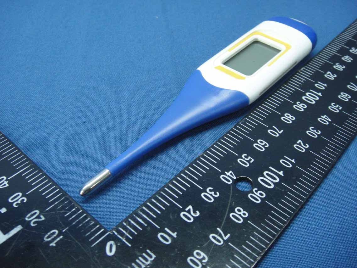
May 13, 2015Digital Thermometer
Equipment Class
DTS - Digital Transmission System
RYZKP-7XXX-590
Apr 28, 2015Bluetooth Medical Device
Equipment Class
DTS - Digital Transmission System