S2MSPLUSDVR BOARD
INTO-TECH Inc.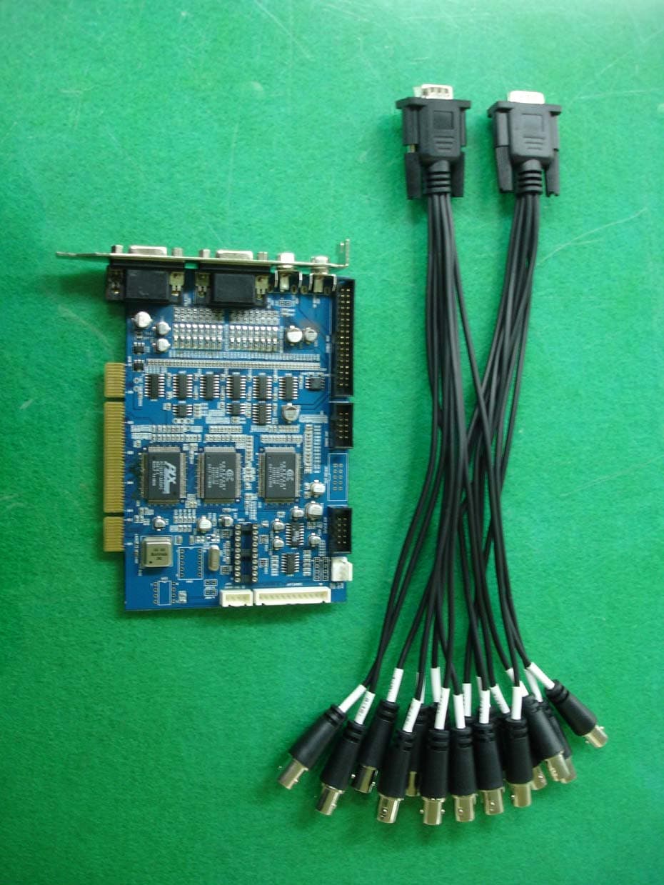
Click to zoom
Application Details
- Equipment Class
- JBP - Part 15 Class B Computing Device Peripheral
- Date of Grant
- Apr 12, 2005
- Application Purpose
- Original Equipment
- Date of Application
- Apr 12, 2005
- Equipment Note
- DVR BOARD
- Company
- INTO-TECH Inc.
- Country
- South Korea
Documents & Files
Document Text
Text extracted from the exhibit documents filed with the FCC. Open a document above to read the original.
Users Manual
Installation Manual 1. Hardware Installation 2.Software Installation User Manual 3.User Manual- Server 01. Main Program 02. Search Program 03. AVI Backup Manager 04. Backup Manager 4.User Manual- Client 01. NetClient Program 02. WebClient Program Annex Annex 1. I/O Device Annex 2. Dynamic IP Annex 3. IP Router To use 16 port In/Out, A : Slave Board must remove jumper. B : Master Board must install jumper. < 16 port In/Out Connection> 5. I/O Board Installation 5-1. Prepare Sensor, Alarm, I/O Board and I/O Extension Board for I/O Board Installation. A : Industrial Case System can use In/Out port separately when additional Back Panel is available. < 8 port In/Out Connection> Installation manual - Software Installation 1. Software Installation You can install SmartDVR Software by using SmartDVR Formula CD or downloading from INTOTECH website, www.intotech.co.kr. Software CD consists of Server Package (Main program, WebClient program, Apache HTTP Server program), Client Package (NetClient program) & AVI Codec. User Manual is also available from SW CD. [Main Program Installation] Insert SmartDVR Formula CD into CD-ROM drive or run DvrSetup.exe file; the following installation screen will appear . Click the icon below and Main Program installation will automatically proceed. Installation Step : Apache HTTP Server (Web Server) -> WebClient -> SmartDVR Formula Installation manual - Software Installation 1. SmartDVR Apache HTTP Server (Web Server) Installation Installation wizard tool will appear. Click [Next]. 1-2 Read the License Agreement and if you agree to the contents, select [I accept...] and click [Next]. 1-3 Click [Next] after checking server information of Apache HTTP Server. Insert Network Domain, Server Name, Administrator’s E-mail Address. (This procedure is only a formality. In general cases, follow example) Select [Run as a service for All Users – Recommended] and click [Next]. Installation manual - Software Installation 1-5 Select Setup Type as [Complete] and click [Next]. 1-6 Click [Next] without change of setting. Note: Do not change the directory! 1-7 After the setting is finished, click [Install] and start installation. 1-8 After the installation is done, click [Finish]. Installation manual - Software Installation 1-9 After the installation is finished, a message confirming the change of the Server port of Apache will appear. 2 SmartDVR WebClient Installation 2-1 After the Installation Wizard Tool is appeared, click [Next]. 2-2 Check the contents of License Agreement; if you agree to the contents, click [Yes]. 2-3 After the installation is done, click [Finish]. Installation manual - Software Installation 3 SmartDVR Formula Installation After Installation Wizard Tool is appeared, Click [Next]. Check the details of License Agreement; if you agree to the contents, click [Yes]. 3-3 After choosing [Destination Folder] for installation, click [Next]. 3-4 After the installation is done, click [Finish]. Installation manual - Software Installation 3-5 Driver Installation: Wizard automatically installs drivers according to each board type. 3-6 Reboot PC after all the installation. 4. SmartDVR Formula Uninstallation 4-1 Goto [Start] – [Control panel] and click [Add/Remove Program]. 4-2 Select [SmartDVR Formula] and click [Change/Remove]. Click the icon below and NetClient Program installation will proceed. 5 NetClient Installation 5-1 After the Installation Wizard Tool is appeared, click [Next]. 5-2 After choosing [Destination Folder] for installation, click [Next]. Installation manual - Software Installation 5-3 After the installation is finished, click [Finish] 6 NetClient Uninstallation 6-1 Goto [Start] – [Control panel] and click [Add/Remove Program]. 6-2 Select [NetClient Plus] and click [Change/Remove]. AVI Codec Installation Click the icon below and AVI Codec installation will proceed. 7-1 AVI Codec Installation diagram. 7-2 After the installation is finished, click [Finish]. User Manual - Main Program 3 Main Program 01. Main Program Main Program enables users to monitor images through PC monitor. The main program supports the following functions: record images, search & playback images and control camera remotely. Image can also be transmitted over the network to any remote site. <Main Program> 1 : Control Panel 2 : Screen Partition Panel 3 : Pan/Tilt Control Panel 4 : Camera Selection Panel 5 : Audio Volume Control Bar 6 : Status Information Panel 1-1 Control Panel Control Panel consists of the following icons: This enables users to run search programs, manually record images and open configuration window. - Search Icon: Search Option. - Configuration Icon: To change setup of program. - Lock Icon:Supports password lock function for Server security. - Recording Icon and All Icon: Record only certain channels – Enable users to manually select certain channels for recording. Record all channels – Click [All] icon and click [REC] icon to record all channels. Search Icon Lock Icon Configuration Icon Recording Icon All Icon 1-3 Pan/Tilt Control Panel Use of Pan/Tilt Camera, 1.Select correct [Receiver] protocol from [Configuration]. 2. Select the channel which is connected to Pan/Tilt camera. 3. Click various buttons from Pan/Tilt Control Panel to control camera. (Pan/Tilt/Zoom/Focus). 1-2 Screen Partition Panel Support 7 kinds of various screen partitions, full-screen and sequence rotation display mode etc. [Screen Partition Panel] Pan/Tilt & Zoom/Focus Button 1-5 Audio Volume Control Bar If Audio input is configured from [Configuration] - [General], audio volume can be controlled from Audio Volume Control Bar. 2 Configuration Configuration Folder consists of [General], [Channel], [Store], [Network], [Schedule], [Maintenance], [Event], [Receiver], [Video Out] and [User Management] sub-panels. Configuration is used for setting Resolution, Image Quality, Motion Detected Recording, I/O, Schedule, Pan/Tilt Receiver Protocol, Network IP setup, etc. 1-4 Camera Selection Panel Click specific …
Text truncated - open the document above for the full version.
Users Manual
User Manual - DVR AVI Backup Manager 1-4. Backup Time Selection Enter the time you wish to start backup from Time Bar. Recorded data is indicated in red. 1-5 Backup Data Converting Click [Converting] icon after entering the limits of the backup time in reference. Click the start time and click [A->B] icon. Start time will automatically appear as below. Select the location of the directory to backup data and click [OK]. Click the end time and click [A->B] icon. End time will automatically appear as below. AVI BackUp Manager can only convert files up to one hour. Backup data time is only indicated when the difference between start time & end time is less than one hour. AVI Backup Processing Windows prompt message indicating AVI Converting End will automatically appear. You have successfully converted your data for storage. User Manual - Backup Manager 1-6 Play Backup Data using Windows Media-Player Our website offers utilities that users can Download & install AVI Formula Codec V 1.0 from www.intotech.co.kr, DownLoad -> Util section to properly replay stored data. You can now replay all AVI format data using your Windows Media Player . Media Player should replay stored data as seen below. 04.Backup Manager Using Intotech Backup Manager recorded images(* iva. data) can be managed efficiently or quickly backup to CD using this software. [Backup Manager Detailed Information] : Transfer data to Backup List. Remove data from Backup List. : Remove all data from Backup List. : Search screen will be displayed in (YUV) screen mode. (Default setting) : Search screen will be displayed in (RGB) screen mode. Graphic Card may not support YUVmode YUVis the default setting. (Please convert to RGB mode when transferring or removing data .) : Play Backup Data. : Start Backup. : Stop Backup. Backup Manager illustrates recorded data by date, channel and time. The following icons are used to help manage your recorded data. User Manual - Backup Manager Add data to Backup List illustrated below. Backup folder & Progress Time Bar is indicated as follows. : Select directory to backup : Direct backup to CD (CD-RW required) 1-4 Clickicon to setup backup directory. 1-5 Choose HDD to backup and click [OK]. Example selects C: Drive. Backup Manager HDD Backup Click Backup Manager icon to run program. 1-2 Select date & time from Data List to Backup. 1-3 Move selected data from Data List to Backup List. Click ( ) icon to move data from Data List to Backup List. Ex) Indicates 2004/ 2/ 7 CH2 10 o’clock. User Manual - Backup Manager 1-6 Click icon to start backup.. 1-7 Message is displayed after completion. 2 CD Backup 2-1 Click Backup Manager icon and run program. 2-2 Select date & time from Data List to Backup. 2-3 Move selected data from Data List to Backup List. Clickicon to move data. Ex) Indicates 2004/ 2/ 7 CH2 10 olock. Clickicon. 2-4 Click [CD – RW] and click [Contain Backup Player]. (NOTE : The Contain Backup Player(7MB) must be checked.) 2-5 Click icon to start backup User Manual - Backup Manager 3 Play HDD Backup Data 3-1 Click Backup Manager and run program. 2-6 Message is displayed after completion. 3-4 Search Data screen illustrated below. a. Recorded data is shown in red. 3-5 Choose date you want to playback and Click [Load]. 3-2 Click [Play] icon to search Backup Data Directory. 3-3 Select RGB Mode and select directory and Click [OK]. User Manual - Backup Manager 3-6 Click icon to exit from playback mode and return to Backup Manager. 4. Play CD Backup Data Insert CD to CDROM. (Run CDROM Drive -> Backup Player -> Click [ ] icon.) Select CDROM directory and click [OK]. [The following Error Messages appear usually means the following errors.] [Error Message] There is no medium in the burner : There is no CD inside CD-RW drive. If you want to Backup CD. Please reboot or end process ‘imap.exe’ : Please reboot PC OR stop imap.exe’ by force from Windows Task Manager. Set CD recorder failed. : Conflict with CD-RW settings. Not Enough Hdd Disk Free Space to Create CD IMAGE : HDD must have enough free space to CD backup data onto CD. The call failed because IMAPI has not been opened with Open. : Your Operating System(O/S) does not support CD Backup. If you have any further tech support issues, please contact your local Intotech DVR dealer. User Manual - NetClient Interface 4 NetClient Interface 01. Intotech Net-Client Interface NetClient Program is able to receive images from DVR Server using the Internet. NetClient functions: Display & recording, camera control from remote site and other features that we will illustrated in this document. Control Panel The Control Panel can search program, open connection setup, save & print still images and record server image from remote PC where NetClient is installed. 1-2 Screen Partition Panel Support 7 kinds of various screen partition, full-screen and sequence rotation display mode. Search Icon:Runs search program. Connection Setup Icon: Run [Connecting & Configuration Management] used for internet access. Run [Modem Connection] used for internet access . 1-3 Pan/Tilt Control Panel Pan / Tilt / Zoom / Focus control is supported from remote site when DVR Server is using Pan/Tilt camera. Control sensitivity can be configured in Control Panel. Only broadband Internet users can use Pan/Tilt control, Modem users cannot use this feature. 1-4 Network Type Selection Panel Select [LAN] from Network Type Selection Panel when using broadband connection and Select [Modem] when using Modem. 1-5 Camera Selection Panel Click specific channel from Camera Selection Panel to enlarge and view image. Search Icon Print IconConnection Setup Save Icon REC Icon All Icon Save Icon:Save selected channels as JPEG file. Print Icon:Print the selected channels in various modes. REC Icon: Record the image of selected channels. All Icon: Select all channels to record. User Manual - NetClient Interface 1-6 Internet User Real-Time Surveillance Click [LAN] from [Network Type Selection Panel] and view real-time …
Text truncated - open the document above for the full version.
External Photos
SK TECH CO., LTD. Page 1 of 2 SKT SKTFCE-050412-024 FCC ID : S2MSPLUS External Photographs of EUT SK TECH CO., LTD. Page 2 of 2 SKT SKTFCE-050412-024 FCC ID : S2MSPLUS
ID Label/Location Info
SK TECH CO., LTD. Page 1 of 1 SKT SKTFCE-050412-024 FCC ID : S2MSPLUS FCC ID Label Sample INTO-TECH Inc. DVR BOARD FCC ID: S2MSPLUS
ID Label/Location Info
SK TECH CO., LTD. Page 1 of 1 SKT SKTFCE-050412-024 FCC ID : S2MSPLUS FCC ID Sample Label & Location Information LABELLING REQUIREMENTS PER ∫∫∫∫2.928 The Label shown shall be permanently affixed at a conspicuous location on the device and be readily visible to the user at the time of purchase. INTO-TECH Inc. DVR BOARD FCC ID :S2MSPLUS
Internal Photos
SK TECH CO., LTD. Page 1 of 1 SKT SKTFCE-050412-024 FCC ID : S2MSPLUS Internal Photographs of EUT
Operational Description
SK TECH CO., LTD. Page 1 of 2 SKT SKTFCE-050412-024 FCC ID :S2MSPLUS Operational Description I. Installation 1. SmartDVR Apache HTTP Server(Web Server) Installation 1-1 Installation wizard tool will appear. Click<Next>. 1-2 Read the License Agreement and if you agree to the contents, select <I accept...>and click<Next>. 1-3 Click<Next> after checking server information of Apache HTTP Server. 1-4 Insert Network Domain, Server Name, Administrator’s E-mail Address. (This procedure is only a formality. In general cases, follow example) Select<Run as a service for All Users-Recommended> and click<Next>. 1-5 Select Setup Type as<Complete>and click<Next>. 1-6 Click<Next>without change of setting. Note: Do not change the directory! 1-7 After the setting is finished, click<Install>and start installation. 1-8 After the installation is done, click<finish>. 1-9 After the installation is finished, a message confirming the change of the Server port of Apache will appear. 2. SmartDVR WebClient Installation 2-1 After the Installation Wizard Tool is appeared, click<next>. 2-2Check the contents of License Agreement; if you agree to contents, click<Yes>. 2-3After the installation is done, click<Finish>. SK TECH CO., LTD. Page 2 of 2 SKT SKTFCE-050412-024 FCC ID :S2MSPLUS 3 SmartDVR Formula Installation 3-1 After Installation Wizard Tool is appeared, click<Next>. 3-2Check the details of License Agreement; Agreement; if you agree to the contents, click<Yes>. 3-3 After choosing <Destination Folder> for installation, click<next>. 3-4After the installation is done, click<Finish>. 3-5Driver Installation: Wizard automatically installs drivers according to each board type. 3-6Reboot PC after all the installation.
Schematics
55 44 33 22 11 D D C C B B A A connect shield to AGNDconnect shield to AGND <Doc> <RevCode> <Title> A3 11 Wednesday, April 13, 2005 TitleSize Document Number Rev Date: Sheet of VIN4 VMIN4 VIN11VIN7 VMIN11VMIN14VMIN9 VIN9 VMIN15 VIN3 VMIN16VMIN6 VIN14VIN1VIN16 VMIN8 VIN6 VMIN7 VIN13VIN10VIN8 VMIN13 VIN12 VMIN3 VIN5 VMIN5 VIN15VIN2 VMIN10VMIN2VMIN1VMIN12 VMIN1VMIN16VMIN1VMIN14VMIN8VMIN11VMIN6VMIN5 SYNC_B VMIN12VMIN10VMIN4VMIN2VMIN15VMIN2VMIN11 MUX_B0 VMIN3VMIN8 MUX_A0 VMIN16VMIN7VMIN13VMIN14VMIN15VMIN5 SYNC_A VMIN7VMIN6VMIN13VMIN3VMIN4VMIN9VMIN10VMIN12VMIN9VMIN4 VIN15 VMIN14VMIN11VMIN5 VIN12 TVOUT VIN4 VMIN8 VIN1 VMIN13 VIN14 VMIN1 VIN11VIN13VIN6 VMIN3VMIN12VMIN10 VIN16 VMIN9VMIN16 VIN5 VMIN2 VIN3VIN7VIN2VIN8 VMIN6 VIN10 VMIN7 VOUT VIN9 VOUT TVOUT VMIN15 AIN0AIN1 SML_ASML_B AIN1AIN0 MUX_B0 ODD_GPIO1 EVEN_GPIO3 MUX_A0 EVEN_GPIO3_NEVEN_GPIO2 ODD_GPIO2ODD_GPIO0 EVEN_GPIO2 ODD_GPIO2ODD_GPIO1 EVEN_GPIO1 ODD_GPIO3_NODD_GPIO3 INTR_A EVEN_GPIO0 ODD_GPIO0 SYNC_A EVEN_GPIO1 SYNC_BINTR_B EVEN_GPIO0 TV_SEL3TV_SEL1TV_SEL1TV_SEL3_NTV_SEL0TV_SEL2TV_SEL2TV_SEL0 SML_BSML_A AVCC VEE AVCC +5VA+5VA VEEVEE +5VA +5VAVEE +5VA +5VA VEE +5VA VEE R43475 C548VARISTOR C442 0.1uF C543VARISTOR U402LM1881 1234 5678 CSOVINVSOGND BGOUT RSET O/E VCC C545VARISTOR C443 0.1uF J412RCA JACK 1 2 L403 BEAD 1 2 C4090.1uF C416 0.1uF U4074051 13141512 15246 1110 9 31687 X0X1X2X3X4X5X6X7INHABC X VDD VSSVEE C433 0.1uF C549VARISTOR C437 0.1uF C453 0.1uF C414 0.1uF C432 0.1uF C415 0.1uF L414 BEAD 1 2 C459 1uF C550VARISTOR R409 33 J409RCA JACK 1 2 C553VARISTOR C544VARISTOR C436 0.1uF C444 0.1uF R405 33 R428 33 C4100.1uF C408 0.1uF L401 BEAD 1 2 C435 0.1uF C407 0.1uF L402 BEAD 1 2 C406 0.1uF R41875 + E405 22uF R41775 C438 0.1uF C458 1uF R406 33 C404 0.1uF C456 0.1uF R449 4.7k R43175 C403 0.1uF R4481k R41575 L407 BEAD 1 2 U4104051 13141512 15246 1110 9 31687 X0X1X2X3X4X5X6X7INHABC X VDD VSSVEE C555VARISTOR C424 0.1uF R404 33 J410HEADER 2 12 J401 DB15-VGA FEMALE 155101449133122711168 C429 0.1uF C401 0.1uF C413 0.1uF C402 0.1uF R401 33 C449 0.1uF R41475 L416 BEAD 1 2 C440 0.1uF R450 4.7k R430 33 L412 BEAD 1 2 R41275 C417 0.1uF C427 0.1uF R421 33 C445 0.1uF U4054051 13141512 15246 1110 9 31687 X0X1X2X3X4X5X6X7INHABC X VDD VSSVEE J413 N.C 12345678910 C556VARISTOR L418 BEAD 1 2 U4044051 13141512 15246 1110 9 31687 X0X1X2X3X4X5X6X7INHABC X VDD VSSVEE R423 33 R43275 R43875 C405 0.1uF C551VARISTOR J406 BOX HEADER 17X2 1234567891011 12 13 14 15 16 17 18 19 20 21 22 23 24 25 26 27 28 29 30 31 32 33 34 C446 0.1uF C447 0.1uF R426 33 C546VARISTOR R49551k R43375 L404 BEAD 1 2 U406LM1881 1234 5678 CSOVINVSOGND BGOUT RSET O/E VCC L408 BEAD 1 2 C423 0.1uF C554VARISTOR C419 0.1uF J405 DB15-VGA FEMALE 155101449133122711168 C451 0.1uF C421 0.1uF C452 0.1uF R402 33 C420 0.1uF C418 0.1uF R408680k R403 33 R447 75 C557VARISTOR R41375 C558VARISTOR R49651k R407 33 C426 0.1uF C455 0.1uF R41975 L417 BEAD 1 2 R425 33 R427 33 C434 0.1uF C450 0.1uF R43675 L409 BEAD 1 2 L413 BEAD 1 2 C439 0.1uF U4084051 13141512 15246 1110 9 31687 X0X1X2X3X4X5X6X7INHABC X VDD VSSVEE L411 BEAD 1 2 C425 0.1uF R41675 R420 33 + E407 100UF R43775 C4310.1uF C422 0.1uF U412JRC2267 1234 5678 VIN1GNDSAG1VOUT1 VOUT2 SAG2 VCC VIN2 C4300.1uF R43575 R429680k U4014051 13141512 15246 1110 9 31687 X0X1X2X3X4X5X6X7INHABC X VDD VSSVEE C441 0.1uF C552VARISTOR C448 0.1uF L415 BEAD 1 2 C547VARISTOR C454 0.1uF L406 BEAD 1 2 55 44 33 22 11 D D C C B B A A oio At89c2051 module o TXData1 RXData1TXData0RXFlagInTXData2 TXFlagOut RXData2 o TXFlagIn io RXData0 RXFlagOut < To I/O_DTMF Board > WDogEn# i i i ii o WDogCntPulse Rs232 to rs422/485 module RS485 setting 2: 1-2 short3-4 open1-2 short RS485 setting 1: 3-4 short 3-4 short RS485 setting : 1-2 short RS422 setting : 1,2,3,4 open or MAX489 connect = rs485 RS422 setting 2: 1,2,3,4 open <Doc> <RevCode> <Title> A3 11 Wednesday, April 13, 2005 TitleSize Document Number Rev Date: Sheet of GPIO_A19 RELAY GPIO_A23 RX_IO GPIO_A18 GPIO_A22 GPIO_A13GPIO_A17GPIO_A11 GPIO_A20 GPIO_A22 GPIO_A12 TX_IO RELAY GPIO_A16GPIO_A15 GPIO_A21 GPIO_A17GPIO_A23GPIO_A21 GPIO_A12GPIO_A15GPIO_A11 GPIO_A20 TX_IO GPIO_A18GPIO_A16 GPIO_A13GPIO_A19 RX_IO RS232RX RS422BORS422AI RS422BO RS422AI RS232TXEN RS232TXEN RS422BI RS232TX RS422AO RS232RX RS422BI RS232TX RS422AO GPIO_A21 GPIO_A11GPIO_A17 GPIO_A22 GPIO_A15GPIO_A19GPIO_A18 GPIO_A23 GPIO_A12GPIO_A16 GPIO_A20 GPIO_A13 NOT_GATE_I NOT_GATE_O VCC VCC VCC VCC VCC VCC VCC VCC VCC VCC VCC VCC VCC VCC R4441k C4280.1uF K401 RELAY TQ2-5V 3 24 8 97 1 10 L405BEAD 12 N403 4.7kN 1234 5678 R443120R4392k R41110M J408HEADER 4 1 2 3 4 X401 22.1184Mhz Q401KSA1015 1 23 R4452k R44110k J403HEADER 2 1 2 N401 4.7kN 1234 5678 U40389C2051 123456789 10 11122019181716151413 RST/VPPP3.0(RX)P3.1(TX)XTAL2XTAL1P3.2(INT0) P3.3(INT1)P3.4(T0)P3.5(T1)GND P3.7 P1.0(AIN0) VCC P1.7P1.6P1.5P1.4P1.3P1.2 P1.1(AIN1) C41120pF E40110uF J402HEADER 4 1234 E40210uF U409 MAX491 1234567 891011121314 NC1RORE DEDIGND1GND2 NC2 Y Z BA NC3 VCC J411HEADER 5X212345678910 J404HEADER 2 1 2 N402 4.7kN 1234 5678 J407HEADER 4 1 2 3 4 U411 MAX232 1345 111012 9 26147138 1615 C1+C1-C2+C2-T1INT2INR1OUTR2OUT V+ V- T1OUTT2OUT R1INR2IN VCCGND E40610uF E403 10uF R4462k R42420 R4422k C41220pF R4401k E40410uF R42210k D4091N4004 2 1 R41010k N404 4.7kN 1234 5678 55 44 33 22 11 D D C C B B A A < for HB1=7> <Doc> <RevCode> <Title> A3 11 Wednesday, April 13, 2005 TitleSize Document Number Rev Date: Sheet of AD18 AD12 AD[0..31] PAD8 PAD7 PAD0AD1AD4 DEVSEL PAD13 AD25 PAD11 PAD[0..31] PCBE1 PAD15 AD15 PAD18 STOP REQ0 PIRDY CBE1 FRAME AD9AD14 RST PAD6 PAD3 PAD20 TRDY PAD10 AD7 PAD22 AD17 AD26 PAD19 CBE2 AD6 PPERR PRST CBE0 PAD16 PAR AD21 SERR AD13PAD2 IRDY AD27 GNT0 AD19 AD0 AD31 PCLKRUNPAD28 PSERR PAD9 AD10 PIDSEL SCLKRUNPAD29 PAD17 LSTATPAD31 AD30 AD20 PERR PAD23 CBE3 AD2 AD24 PCBE2 PREQ AD11 PSTOP REQ3 PAD12 PAD5 AD29 PAD27 PCBE3 PDEVSEL PAD14 REQ2 PCLKB AD8 SPCLK0 AD23 PFRAME PAD30 PCBE0 PAD24 AD5AD3 AD22 REQ1 AD16 PPAR PAD25 GNT1 PAD21 AD28 PAD4 PTRDY PAD26 PAD1 PGNT SPCLK1 IRDY PAD21 REQ1 PAD3 PAD20 PAD7 PAD18 PIDSELP…
Text truncated - open the document above for the full version.
Test Report
SK TECH CO., LTD. Page 1 of 16 SKT SKTFCE-050412-024 FCC ID : S2MSPLUS Certificate of Compliance Test Report No.: SKTFCE-050412-024 NVLAP CODE : 200220-0 Applicant: INTO-TECH Inc. Applicant Address: 3F, Seojin Bldg., 1-17, Cheongdam-Dong, Gangnam-Gu, Seoul, 135-100, KOREA Manufacturer: INTO-TECH Inc. Manufacture Address: 3F, Seojin Bldg., 1-17, Cheongdam-Dong, Gangnam-Gu, Seoul, 135-100, KOREA Product: DVR BOARD FCC ID: S2MSPLUS Model No.: SPLUS Receipt No.: SKTEU05-0013 Date of receipt: Jan. 12, 2005 Date of Issue: Apr. 12, 2005 Testing location: SK TECH CO., LTD. 820-2, Wolmoon-Ri, Wabu-Up, Namyangju-Si, Kyunggi-Do, Korea Test Standards: ANSI C63.4 / 2003 Rule Parts: FCC part 15 Subpart B Equipment Class : Class B Digital Device Peripheral Test Result: The above mentioned product has been tested and passed. Prepared by: S.Y.Ye Tested by: S.H.Yoon/Engineer Approved by: C.H.Jeong /Manager& Chief Engineer Signature Date Signature Date Signature Date Other Aspects : Abbreviations : · OK, Pass = passed · Fail = failed · N/A = not applicable ☞ •This test report is not permitted to copy partly without our permission. •This test result is dependent on only equipment to be used. •This test result is based on a single evaluation of one sample of the above mentioned. •This test report must not be used by the client to claim product endorsement by NVLAP or any agency of the U.S Government. • We certify that this test report has been based on the measurement standards that is traceable to the national or International standards. NVLAP Lab. Code: 200220-0 SK TECH CO., LTD. Page 2 of 16 SKT SKTFCE-050412-024 FCC ID : S2MSPLUS 》》 Contents 《《 Contents 2 List of Tables 2 List of Figures 2 1. General 3 2. Test Site 3 2.1 Location 3 2.2 List of Test and Measurement Instruments 4 2.3 Test Date 4 2.4 Test Environment 4 3. Description of the tested samples 5 3.1 Rating and Physical Characteristics 5 3.2 Submitted Documents 5 4. Measurement Conditions 6 4.1 Modes of Operation 6 4.2 List of Peripherals 6 4.3 Type of Used cables 7 4.4 Test Setup 7 4.5 Uncertainty 8 5. EMISSION Test 11 5.1 Conducted Emissions 11 5.2 Radiated Emissions 15 》List of Tables Table 1 List of test and measurement Equipment 4 Table 2 Test Data, Conducted Emissions 14 Table 3 Test Data, Radiated Emissions 16 》List of Figures Figure 1 Spectral Diagram, LINE-PE 12 Figure 2 Spectral Diagram, Neutral-PE 13 SK TECH CO., LTD. Page 3 of 16 SKT SKTFCE-050412-024 FCC ID : S2MSPLUS 1. General This equipment has been shown to be capable of compliance with the applicable technical standards and was tested in accordance with the measurement procedures as indicated in this report. We attest to the accuracy of data. All measurements reported herein were performed by SK Tech Co., Ltd. and were made under Chief Engineer’s supervision. We assume full responsibility for the completeness of these measurements and vouch for the qualifications of all persons taking them. 2. Test Site SK TECH Co., Ltd. 2.1 Location 820-2, Wolmoon Ri, Wabu-Up, Namyangju-Si, Kyunggi-Do, Korea The test site is in compliance with ISO/IEC 17025 for general requirements for the competence of testing and calibration laboratories. This laboratory is accredited by NVLAP for NVLAP Lab. Code : 200220-0 and DATech for DAR-Registration No.:DAT-P-076/97-01 SK TECH CO., LTD. Page 4 of 16 SKT SKTFCE-050412-024 FCC ID : S2MSPLUS 2.2 List of Test and Measurement Instruments Table 1 : List of Test and Measurement Equipment z Conducted Disturbance Kind of Equipment Type S/N Calibrated until EMI Receiver ESHS10 862970/019 10.2005 Artificial Mains Network ESH2-Z5 834549/011 08.2005 EMI Receiver ESHS10 835871/002 11.2005 Artificial Mains Network ESH3-Z5 836679/018 08.2005 z Radiated Disturbance Kind of Equipment Type S/N Calibrated until EMI Receiver ESVS 10 825120/013 10.2005 EMI Receiver ESVS 10 834468/008 11.2005 Spectrum Analyzer R3361A 11730187 10.2005 Amplifier 8447F 3113A05153 08.2005 Log Periodic Antenna UHALP9107 1819 04.2005 Biconical Antenna BBA9106 91031626 04.2005 Open Site Cable N/A N/A N/A Antenna Turntable Driver 5907 N/A N/A Antenna Turntable controller 5906 N/A N/A Amp & Receiver connection cable N/A N/A N/A Amp & Spectrum connection cable N/A N/A N/A 50Ω Switcher MP59B 6100214538 N/A 2.3 Test Date Date of Application : Jan. 12, 2005 Date of Test : Jan. 14, 2005 ~ Jan. 18, 2005 2.4 Test Environment See each test item’s description. SK TECH CO., LTD. Page 5 of 16 SKT SKTFCE-050412-024 FCC ID : S2MSPLUS 3. Description of the tested samples The EUT is the DVR BOARD built in computer. 3.1 Rating and Physical Characteristics 1.Board Spec. Category Specification Video Input Max 16 Ch Rated input voltage +3.3V/ 5.0Vd.c. Rated input current 0.06A / 0.64A TV Output 1 Ch Switching Audio Input Digital Audio Board 4 Ch (Option Board) Analog Audio Max 2 Ch NTSC PAL Display FPS 60 FPS 50 FPS Record FPS 60 FPS 50 FPS Resolution Support 640 * 480 / 320 * 240 720* 576 / 360 * 288 Compression 2-3KB/fps Codec Formula (Modified H.263) Digital I/O Digital IO Board(Option Board) MAX 16 Ch/16 Ch (In/Out) Camera Control P/T/Z Focus Preset 2.Minimum System Requirements. Category Specification CPU Celeron Processor 1.7 Main Board Intel 845G Chipset RAM 256Mbyte OS Windows 2000 / XP VGA 16Bit Color & YUY2 Directx Mode, Graphic Card (Over 32MB RAM) 3.2 Submitted Documents N/A SK TECH CO., LTD. Page 6 of 16 SKT SKTFCE-050412-024 FCC ID : S2MSPLUS 4. Measurement Conditions The operating voltage of EUT is supplied by PCI slot of Personal Computer. (AC Adapter Input Voltage : AC 120V, 60Hz) 4.1 Modes of Operation The EUT was in the following operation mode during all testing; After the EUT has received the video signal from the video camera, the signal was displayed in the CRT Monitor and PC monitor through the EUT. 4.2 List of Peripherals Description Manufacturer Model Name Serial No. FCC ID Keyboard(PS2) Jing Mold Enterprise Co., Ltd. LKB-0107 20103462 - Mouse(USB) LG LMULBGS01I 04CU000259 - Printer(Parallel) E…
Text truncated - open the document above for the full version.
Test Setup Photos
SK TECH CO., LTD. Page 1 of 2 SKT SKTFCE-050412-024 FCC ID :S2MSPLUS Test set up photos Photograph 1: Setup for Conducted Emissions SK TECH CO., LTD. Page 2 of 2 SKT SKTFCE-050412-024 FCC ID :S2MSPLUS Photograph 2: Setup for Radiated Emissions
Contact Information
Applicant
Sam-Soon Choi(Assistant Manager)
Test Firm
SK Tech Co., Ltd.Jae-Yeong Hyun
Technical Specifications
| # | Rule Parts | Frequency Range | Power Output |
|---|---|---|---|
| 1 | 15B | - | - |
Other Applications from INTO-TECH Inc.
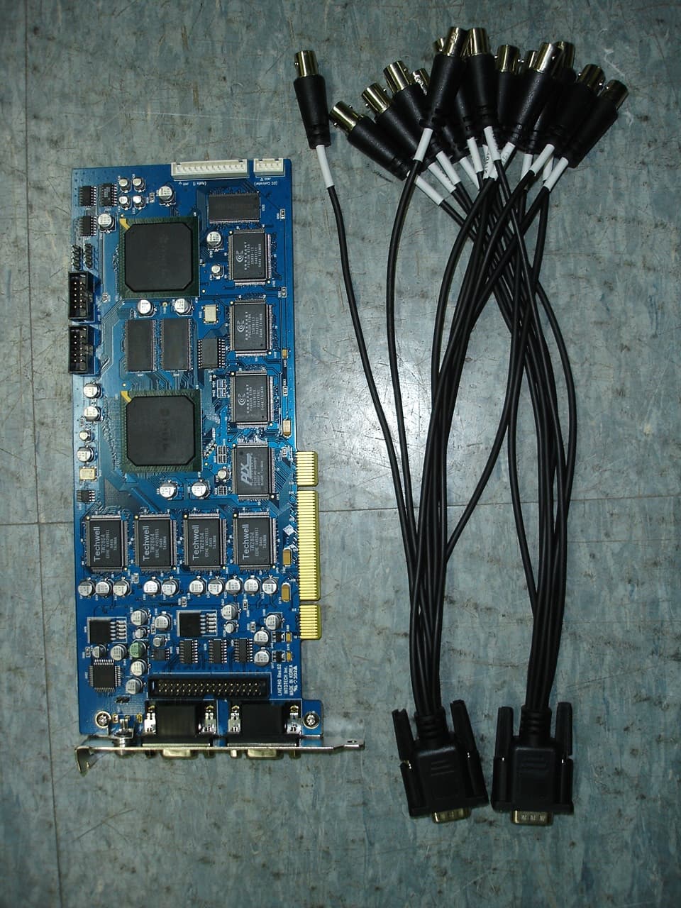
S2MLIVE240
Jun 05, 2005DVR BOARD
Equipment Class
JBP - Part 15 Class B Computing Device Peripheral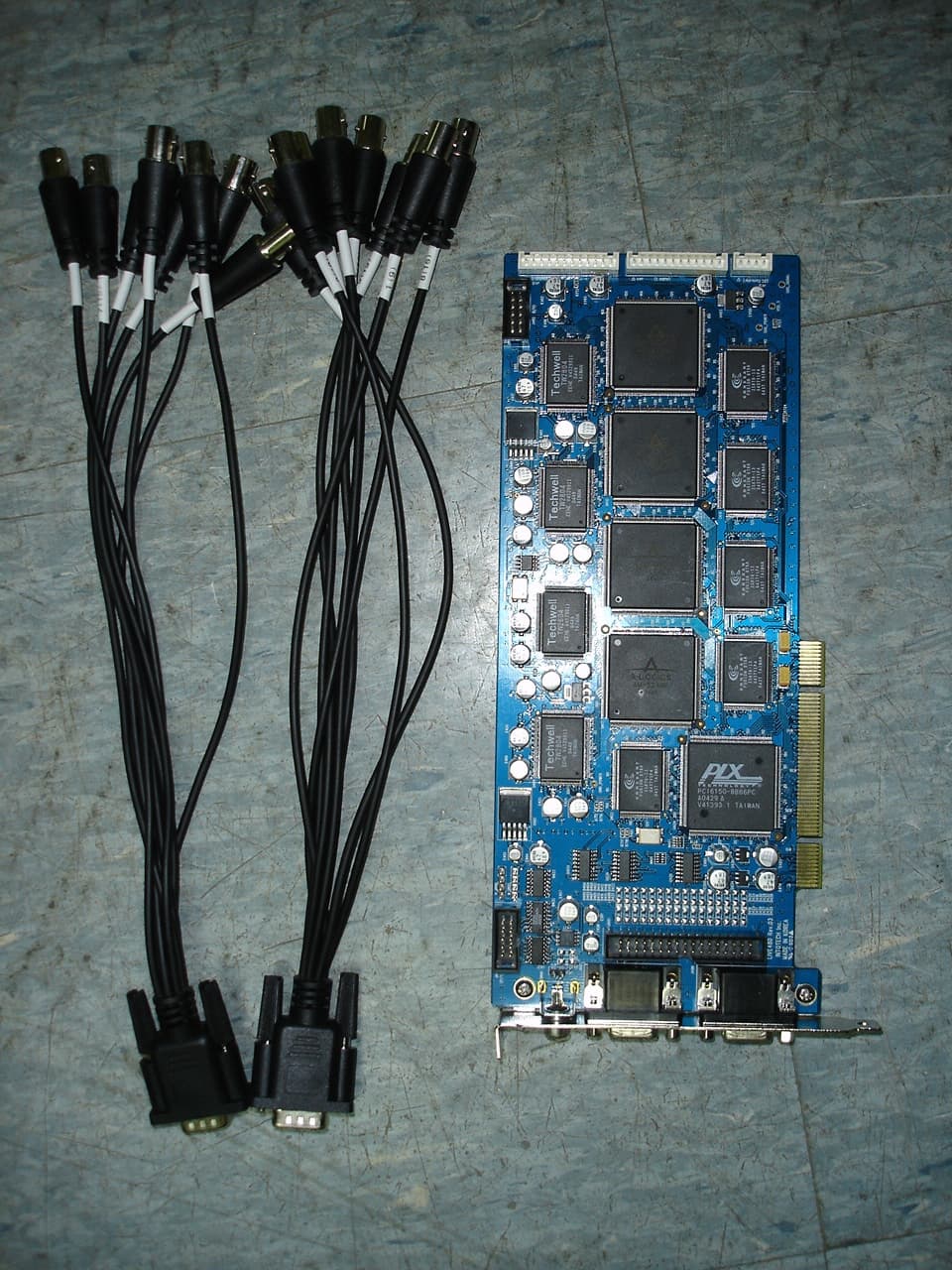
S2MLIVE480
Jun 05, 2005DVR BOARD
Equipment Class
JBP - Part 15 Class B Computing Device Peripheral
S2MLIVE120
Apr 11, 2005DVR BOARD
Equipment Class
JBP - Part 15 Class B Computing Device Peripheral