S2SF007THWireless Thermo-Hygrometer
Ambient, LLC dba Ambient Weather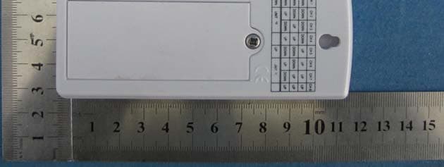
Click to zoom
Application Details
- Equipment Class
- DSC - Part 15 Security/Remote Control Transmitter
- Date of Grant
- Apr 15, 2013
- Application Purpose
- Original Equipment
- Date of Application
- Apr 15, 2013
- Equipment Note
- Wireless Thermo-Hygrometer
- Frequency Range
- 433.92000000 - 433.92000000
- Country
- United States
Documents & Files
Document Text
Text extracted from the exhibit documents filed with the FCC. Open a document above to read the original.
Users Manual
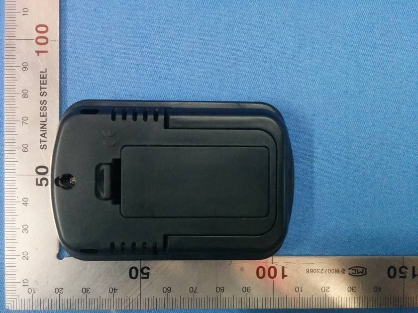
Version 1.0 ©Copyright 2013, Ambient LLC. All Rights Reserved. Page 1 Table of Contents ......................................................................................2 .......................................................................................2 ..................................................................................2 .........................................................................2 .................................................2 ................................................................4 .........................................................5 ................................................6 ..................................................................6 .................................................................................7 ................................................................................7 .....................................................................7 .............................................................................7 .................................................................... 8 ............................................................8 ...............................9 ........................................................9 ...........................................................10 ..................................................10 ........................................................................11 .......................................................................11 ..............................................................11 ..................................................12 ..............................................................12 ................................................................12 ................................................................................14 ...................................................................14 ........................................................................15 ......................................................................15 1. Introduction 2.Getting Started 2.1 Parts List 2.2 Recommend Tools 2.3 Thermo-Hygrometer Sensor Set Up 2.4Display Console Set Up 2.4.1 Display Console Layout 2.4.2 Sensor Operation Verification 3.Remote Sensor Installation 4.Display Features 4.1 Comfort Icon 4.2 Rate of Change Icon 5.Console Operation 5.1 Min/Max Mode ........8 5.2 5.3 Temperature Units of Measure 5.4 Sensor Search Mode 5.5 Best Practices for Wireless Communication 5.6 Adjustment or Calibration 5.6.1 Humidity Calibration 5.6.2 Temperature Calibration 6.Glossary of Terms 7.Specifications 7.1 Wireless Specifications 7.2 Measurement Specifications 7.3 Power Consumption 8.Troubleshooting Guide 9.Accessories 10.Liability Disclaimer 11.FCC Statement 12.Warranty Information Indoor/Outdoor Channel Selection ...... ....................................................8 .............................................. Ambient Weather WS-07 Wireless Indoor/Outdoor 8- Channel Thermo-Hygrometer with Jumbo Display User Manual 1. Introduction Thank you for your purchase of the Ambient Weather WS-07 Wireless Indoor/Outdoor 8-Channel Thermo-Hygrometer with Jumbo Display. The following user guide provides step by step instructions for installation, operation and troubleshooting. To download the latest manual and additional troubleshooting tips, please visit: 2.Getting Started Note: The power up sequence must be performed in the order shown in this section (insert batteries in the remote transmitter(s) first, Display Console second). The WS-07 weather station consists of a display console (receiver), and a thermo-hygrometer (remote transmitter). 2.1 Parts List 2.2 Recommend Tools Hammer and nail for hanging remote thermo-hygrometer transmitter. 2.3 Thermo-Hygrometer Sensor Set Up Note: Do not use rechargeable batteries. We recommend fresh alkaline batteries for outdoor temperature ranges between -4 °F and 140 °F and fresh lithium batteries for outdoor temperature ranges between -40 °F and 140 °F. 1. Remove the battery door on the back of the sensor by removing the set screw, as shown in Figure 1 . http://ambientweather.wikispaces.com/ws07 QTY Item Display Console Frame Dimensions (LxHxW): 4.50 x 5.0 x 1.00 in LCD Dimensions (LxW): 3.75 x 3.50” LCD Segment Height: 1.25 inches Thermo-hygrometer transmitter (FT007TH) Dimensions (LxHxW): 4.5” x 2.0” x 0.75” 1 1 Version 1.0 ©Copyright 2013, Ambient LLC. All Rights Reserved. Page 2 LED Figure 1 2. BEFORE inserting the batteries, locate the dip switches on the inside cover of the lid of the transmitter. Figure 2 Figure 2 3. Channel Number: The WS-07 supports up to eight transmitters. To set each channel number (the default is Channel 1), change Dip Switches 1, 2 and 3, as referenced in Table 1. 4. Temperature Units of Measure: To change the transmitter display units of measure (°F vs. °C), change Dip Switch 4, as referenced in Table 1. Table 1 displays all four switches in the OFF position (factory default setting). Version 1.0 ©Copyright 2013, Ambient LLC. All Rights Reserved. Page 3 DIP SWITCH FUNCTION Channel 1 Channel 2 Channel 3 Channel 4 Channel 5 Channel 6 Channel 7 Channel 8 °F °C 5. In se rt t w o A A A b at ter i e s . 6. After inserting the batteries, the remote sensor LED indicator will light for 4 seconds, and then flash once per 60 seconds thereafter . Each time it flashes, the sensor is transmitting data. 7. V erify the correct channel number (CH) and temperature units of measure (°F vs. °C) are on the display , as shown in Figure 3 . Figure 3 ( 1 ) t em p e r a t ur e (2 ) t e m p e ra t u r e u n i ts (° F vs. °C) (3 ) c h a n nel nu m b e r (4) relative humidity 8. Close the battery door. Make sure the gasket (around the battery compartment) is properly seated in its trace prior to closing the door . T ighten the set screw. 2.4 Display Console Set Up 1. Move the remote thermo-hygrometer(s) about 5 to 10' away from the display console (if the sensor…
Text truncated - open the document above for the full version.
Test Report
Global United Technology Services Co., Ltd. Report No.: GTSE13030025801 Authorized Signature: Robinson Lo Laboratory Manager This report details the results of the testing carried out on one sample. The results contained in this test report do not relate to other samples of the same product and does not permit the use of the GTS product certification mark. The manufacturer should ensure that all products in series production are in conformity with the product sample detailed in this report. This report may only be reproduced and distributed in full. If the product in this report is used in any configuration other than that detailed in the report, the manufacturer must ensure the new system complies with all relevant standards. Any mention of GTS International Electrical Approvals or testing done by GTS International Electrical Approvals in connection with, distribution or use of the product described in this report must be approved by GTS International Electrical Approvals in writing. This document cannot be reproduced except in full, without prior written approval of the Company. Any unauthorized alteration, forgery or falsification of the content or appearance of this document is unlawful and offenders may be prosecuted to the fullest extent of the law. Unless otherwise stated the results shown in this test report refer only to the sample(s) tested and such sample(s) are retained for 90 days only.” 1 Cover PageFCC REPORT Applicant: Ambient, LLC dba Ambient Weather Address of Applicant: 6845 W. Frye Road Chandler, AZ 85226 Equipment Under Test (EUT) Product Name: Wireless Thermo-Hygrometer Model No.: F007TH, F007T FCC ID: S2SF007TH Applicable standards: FCC CFR Title 47 Part 15 Subpart C Section 15.231:2012 Date of sample receipt: March 20, 2013 Date of Test: March 21-28, 2013 Date of report issue: March 29, 2013 Test Result : PASS * * In the configuration tested, the EUT complied with the standards specified above. Report No.: GTSE13030025801 Global United Technology Services Co., Ltd. Project No.: GTSE130300258RF 2nd Floor, Block No.2, Laodong Industrial Zone, Xixiang Road Baoan District, Shenzhen, China 518102 Telephone: +86 (0) 755 2779 8480 Fax: +86 (0) 755 2779 8960 Page 2 of 25 2 Version Version No. Date Description 00 March 29, 2013 Original Prepared by: Date: March 29, 2013 Project Engineer Reviewed by: Date: March 29, 2013 Reviewer Report No.: GTSE13030025801 Global United Technology Services Co., Ltd. Project No.: GTSE130300258RF 2nd Floor, Block No.2, Laodong Industrial Zone, Xixiang Road Baoan District, Shenzhen, China 518102 Telephone: +86 (0) 755 2779 8480 Fax: +86 (0) 755 2779 8960 Page 3 of 25 3 Contents Page 1 COVER PAGE .......................................................................................................................................... 1 2 VERSION .................................................................................................................................................. 2 3 CONTENTS .............................................................................................................................................. 3 4 TEST SUMMARY ..................................................................................................................................... 4 5 GENERAL INFORMATION ...................................................................................................................... 5 5.1 CLIENT INFORMATION.......................................................................................................................... 5 5.2 GENERAL DESCRIPTION OF EUT ......................................................................................................... 5 5.3 TEST MODE........................................................................................................................................ 5 5.4 DESCRIPTION OF SUPPORT UNITS....................................................................................................... 6 5.5 TEST FACILITY.................................................................................................................................... 6 5.6 TEST LOCATION.................................................................................................................................. 6 6 TEST INSTRUMENTS LIST ..................................................................................................................... 7 7 TEST RESULTS AND MEASUREMENT DATA...................................................................................... 8 7.1 ANTENNA REQUIREMENT: .................................................................................................................... 8 7.2 RADIATED EMISSION........................................................................................................................... 9 7.2.1 Field Strength Of The Fundamental Signal ............................................................................... 11 7.2.2 Spurious Emissions ................................................................................................................... 13 7.3 20DB BANDWIDTH............................................................................................................................ 16 7.4 DWELL TIME..................................................................................................................................... 17 7.5 SILENT PERIOD................................................................................................................................. 18 8 TEST SETUP PHOTO ............................................................................................................................ 19 9 EUT CONSTRUCTIONAL DETAILS .....................................................................................................20 Report No.: GTSE13030025801 Global United Technology Services Co., Ltd. Project No.: GTSE130300258RF 2nd Floor, Block No.2, …
Text truncated - open the document above for the full version.
Test Setup Photos
Radiated Emission
Contact Information
Applicant
Edward Edelman(President)
Test Firm
Global United Technology Service Co., LtdRobinson Lo
Technical Specifications
| # | Rule Parts | Frequency Range | Power Output |
|---|---|---|---|
| 1 | 15.231(e) | 433.92 MHz - 433.92 MHz | - |
Other Applications from Ambient, LLC dba Ambient Weather
S2SWS40
May 17, 2015Wireless Thermometer
Equipment Class
CYY - Communications Receiver used w/Pt 15 Transmitter
S2SWS11
Aug 08, 2014Weather Station
Equipment Class
CYY - Communications Receiver used w/Pt 15 Transmitter
S2SF007PF
Aug 21, 2013Wireless Thermometer
Equipment Class
DSC - Part 15 Security/Remote Control Transmitter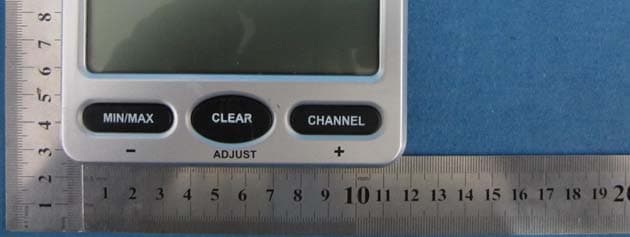
S2SWS07
Apr 15, 2013Wireless Thermo-Hygrometer
Equipment Class
CYY - Communications Receiver used w/Pt 15 Transmitter