S3PCM91Two Way Wireless Transceiver Module
Alutron Modules Inc.Application Details
- Equipment Class
- DTS - Digital Transmission System
- Date of Grant
- Jun 17, 2008
- Application Purpose
- Original Equipment
- Date of Application
- Jun 17, 2008
- Equipment Note
- Two Way Wireless Transceiver Module
- Frequency Range
- 914.90000000 - 914.90000000
- Company
- Alutron Modules Inc.
- Country
- Canada
Documents & Files
Document Text
Text extracted from the exhibit documents filed with the FCC. Open a document above to read the original.
Cover Letter(s)
February 04, 2008 Nemko Canada Inc 303 River Road Ottawa, Ontario, Canada K1V 1H2 Attn: Director of Certification Authority to Act as Agent Onour behalf,I appoint NemkoCanadaInc,303 River RoadOttawaK1V 1H2 ONTARIO, Canadato actas our agent in thepreparation of this application for equipment certification. I certify that submitted documents properly describe the device or system forwhich equipment certification is sought. I also certify that each unit manufactured, imported or marketed, as defined in the Federal Communications Commission’s regulations will have affixed to it a label identical to that submitted for approval with thisapplication. For instances where our authorized agent signs the application for certification on our behalf, I acknowledge that all responsibility for complying with the terms and conditions for certification, as specified by Nemko Canada Inc, still resides with _____________( applicant name and address). Dated this 04Day ofFebruary2008 Agency agreement expiration date:12 Months By:DAN PAUL SignaturePrinted Title:Engineering Manager Onbehalf of :Alutron Modules Inc. Telephone:905 727-8788
Cover Letter(s)
Request for Modular Approval PART 15 UNLICENSED MODULAR TRANSMITTERAPPROVALS Thisletter is intended to be an overview of the module subjected to Modular Transmitter Approval. Alutron Modules Inc.has developed a standalone low power RF transceiver intended for central vacuum applications. It is called CM91 and the main application will be a remote ON/OFF function. The CM91 is a complete RF transceiver and it containsits ownmicrocontroller, reference oscillator VCO and antenna. The only connectors to themodulesarepower supply and modulation/data inputs. The output power islimited to bellow 1mW of RFpower. Therequirementsfor Modular TransmitterApproval areidentified belowand submittedin the application forequipment authorization. 1. TheCM91modular transmitterhasits own RF shieldingin a form of 0.7x2.0 inches of aluminum or copper foil wrapped around the RF section only. This is intended to ensure that the module doesnot have to rely upon the shielding provided by the device into which it is installed in order for all modular transmitter emissions to comply with Part 15 limits. It is also intended to prevent coupling between the RF circuitry of the module and any wiresor circuits in the device into which the module is installed. Such coupling may result in non-compliant operation. 2. The modular transmitterhasmodulation/datainputs toensure that the module will comply with Part 15 requirements underconditions of excessive data rates or over-modulation. 3. The modular transmitterhasits own power supply regulationin the range of 1.8V to 3.6VDC. This is intended to ensure that the module will comply with Part 15 requirements regardless of the design of the power supplying circuitry in the device into which the module is installed.This range is ideal for a wall adaptor or a battery as sources of power, and is intended to offer flexibility in the power supply options that we might have. 4. The modular transmittercomplieswith the antenna requirements of Section 15.203 and 15.204(c). The antennaispermanently attachedas a 3.25 inchof24AWG wire. 5. The modular transmitteristested in a stand-alone configuration, i.e., the modulewillnot be inside another device during testing. This is intended to demonstrate that the module is capable of complying with Part 15 emission limits regardless of the device into which it is eventually installed. Unless the transmitter module will be battery powered, it must comply with the AC line conducted requirements found in Section 15.207. AC or DC power lines and data input/output lines connected to the module must not containferrites unlessthey will be marketed with the module (see Section 15.27(a)). The length of these lines shall be length typical of actual use or, if that length is unknown, at least 10 centimeters to insure that there is no coupling between the case of the module and supporting equipment. Any accessories, peripherals, or support equipment connected to the module during testingwillbe unmodified or commercially available. 6. The modular transmitterwillbe labeled with its own FCC ID number, and, if theFCC ID is not visible when the module is installed inside another device, then the outside of the device into which the module is installed must also display a label referring to the enclosed module. This exterior labelwill be usingwording such as the following: "Contains Transmitter Module FCC ID:S3PCM91" or "Contains FCC ID:S3PCM91." Any similar wording that expresses the same meaning may be used. The Grantee may either provide such a label, an example of whichisincluded in the application for equipment authorization, or, must provide adequate instructions along with the module which explain this requirement. In the latter case, a copy of these instructions mustbe includedin the application for equipment authorization. 7. The modular transmitter complieswith any specific rule or operatingrequirements applicableto the transmitter and the manufacturerwillprovide adequateinstructions alongwith the module to explain any such requirements. A copy ofthese instructionswillbe included in the application for equipment authorization. For example, there arevery strict operational and timing requirements that must be met before a transmitter is authorized for operation under Section 15.231. For instance, data transmission isprohibited, except for operation under Section 15.231(e), in which case there are separate field strength level and timing requirements. Compliance with these requirementsis assured. 8. The modular transmittercomplieswith any applicable RF exposure requirements. For example, FCC Rules in Sections 2.1091, 2.1093 and specific Sections of Part 15, including 15.319(i), 15.407(f), 15.253(f) and 15.255(g), require that Unlicensed PCS, UNII and millimeter wave devices perform routine environmental evaluation for RF Exposure to demonstrate compliance. In addition, spread spectrum transmitters operating under Section 15.247 are required to address RF Exposure compliance in accordance with Section 15.247(b)(4). Modular transmitters approved under other Sections of Part 15, when necessary, may also need to address certain RF Exposure concerns, typically by providing specific installation and operating instructions for users, installers and other interested parties to ensure compliance. Thanks, Dan Paul M.Sc. Engineering Manager Alutron Modules & Power Excellence 420 Industrial Parkway South, Aurora, Ontario, Canada L4G 3V7 B) 905-727-8788 ext 325 F) 905-727-8978 T) 877-807-7168
RF Exposure Info
Prediction of MPE limit at a given distance CM91 Equation from page 18 of OET Bulletin 65, Edition 97-01 where:S = power density P = power input to the antenna G = power gain of the antenna in the direction of interest relative to an isotropic radiator R = distance to the center of radiation of the antenna Maximum peak output power at device output terminal:3.07(dBm) Cable and Jumper loss0.0(dB) Maximum peak output power at antenna input terminal:3.07(dBm) Maximum peak output power at antenna input terminal:2.02768272(mW) Single Antenna gain(typical):6(dBi) Number of Antennae1 Total Antenna gain(typical):6(dBi) Maximum antenna gain:3.981071706(numeric) Prediction distance:20(cm) Prediction frequency:914.9(MHz) MPE limit for uncontrolled exposure at prediction frequency:0.609933333(mW/cm^2) Power density at prediction frequency:0.001606(mW/cm^2) 0.016059(W/m^2) Maximum allowable antenna gain:31.79552224(dBi) Margin of Compliance:25.79552224 dB 2 4R PG S π =
Test Report
www.nemko.com Test Report: 100478-1TRFWL Applicant: Alutron Modules Inc. 420 Industrial Parkway South Aurora, ON L4G 3V7 Apparatus: CM91 FCC ID: S3PCM91 In Accordance With: FCC Part 15 Subpart C, 15.247 FHSS System and Digitally Modulated Radiators 902-928MHz, 2400 - 2483.5 MHz, 5725-5850MHz Tested By: Nemko Canada Inc. 303 River Road Ottawa, Ontario K1V 1H2 Authorized By: Jason Nixon, Wireless/Telecom Specialist Date: June 10, 2008 Total Number of Pages: 24 FCC Part 15 Subpart C, 15.247 : October 2006 Nemko Canada Inc. REPORT SUMMARY Report Number: 100478-1TRFWL FCC ID: S3PCM91 Specification: FCC Part 15 Subpart C, 15.247 Report Summary These tests were conducted on a sample of the equipment for the purpose of demonstrating compliance with Part 15, Subpart C. Radiated tests were conducted in accordance with ANSI C63.4-2003. A description of the test facility is on file with the FCC. The assessment summary is as follows: Apparatus Assessed: CM91 Specification: FCC Part 15 Subpart C, 15.247 Compliance Status: Complies Exclusions: None Non-compliances: None Report Release History: Original Release Author: Andrey Adelberg EMC/Wireless Specialist Note that the results contained in this report relate only to the items tested and were obtained in the period between the date of initial receipt of samples and the date of issue of the report. This test report has been completed in accordance with the requirements of ISO/IEC 17025. Nemko Canada Inc. authorizes the applicant to reproduce this report provided it is reproduced in its entirety and for use by the company’s employees only. Any use which a third party makes of this report, or any reliance on or decisions to be made based on it, are the responsibility of such third parties. Nemko Canada Inc. accepts no responsibility for damages, if any, suffered by any third party as a result of decisions made or actions based on this report. Page 2 of 24 Nemko Canada Inc. REPORT SUMMARY Report Number: 100478-1TRFWL FCC ID: S3PCM91 Specification: FCC Part 15 Subpart C, 15.247 TABLE OF CONTENTS Report Summary.........................................................................................................................................2 Section 1 : Equipment Under Test.............................................................................................................4 1.1 Product Identification.................................................................................................................................4 1.2 Samples Submitted for Assessment............................................................................................................4 1.3 Technical Specifications of the EUT..........................................................................................................5 1.4 Block Diagram of the EUT.........................................................................................................................5 Section 2 : Test Conditions.........................................................................................................................6 2.1 Specifications.............................................................................................................................................6 2.2 Deviations From Laboratory Test Procedures ............................................................................................6 2.3 Test Environment.......................................................................................................................................6 2.4 Test Equipment...........................................................................................................................................6 2.5 Measurement Uncertainty...........................................................................................................................6 Section 3 : Observations.............................................................................................................................7 3.1 Modifications Performed During Assessment ............................................................................................7 3.2 Record Of Technical Judgements...............................................................................................................7 3.3 EUT Parameters Affecting Compliance.....................................................................................................7 3.4 Test Deleted................................................................................................................................................7 3.5 Additional Observations.............................................................................................................................7 Section 4 : Results Summary.....................................................................................................................8 4.1 FCC Part 15 Subpart C : Test Results........................................................................................................9 Appendix A : Test Results........................................................................................................................10 Clause 15.109(a) Radiated Emissions..................................................................................................................10 Clause 15.207(a) Powerline Conducted Emissions.............................................................................................12 Clause 15.209(a) Radiated Emissions within Restricted Bands..........................................................................14 Clause 15.247(a)(2) Minimum 6 dB Bandwidth.................................................................................................16 Clause 15.247(b)(3) Maximum peak output power of systems using digital modulation in the 902-928 MHz, 2400-2483.5 MHz, and 5725-5850 MHz bands......................................................................…
Text truncated - open the document above for the full version.
Contact Information
Applicant
Dan Paul(Engineering Manager)
Technical Contact
Alutron Modules Inc.Mircea Dan Paul
[email protected]905 727-8788
420 Industrial Parkway South · Aurora · Canada
Non-Technical Contact
Alutron Modules Inc.Jack Mawdsley
[email protected]905 727-8788
Test Firm
Nemko Canada IncStuart Beck
Technical Specifications
| # | Rule Parts | Frequency Range | Power Output |
|---|---|---|---|
| 1 | 15C | 914.9 MHz - 914.9 MHz | 2.00 mW |
Other Applications from Alutron Modules Inc.
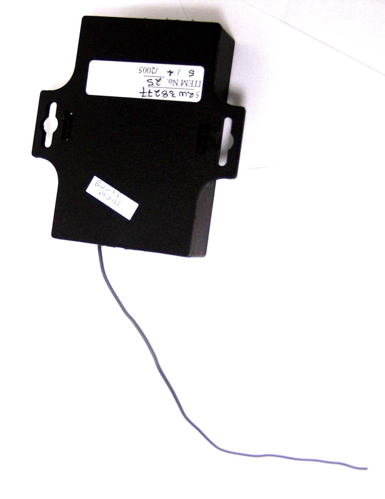
S3PRFR
Aug 25, 2005Central Vacuum Remote Control Receiver
Equipment Class
CYY - Communications Receiver used w/Pt 15 Transmitter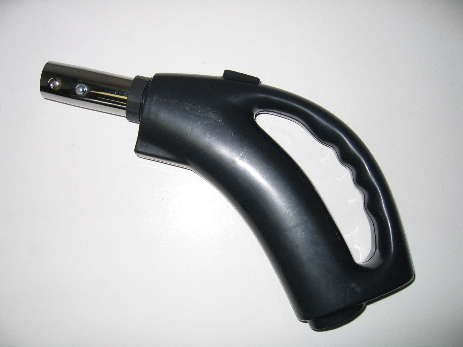
S3PHHRFT
May 10, 2005Hose-handle RF Transmitter
Equipment Class
DSC - Part 15 Security/Remote Control Transmitter