S3PHHRFTHose-handle RF Transmitter
Alutron Modules Inc.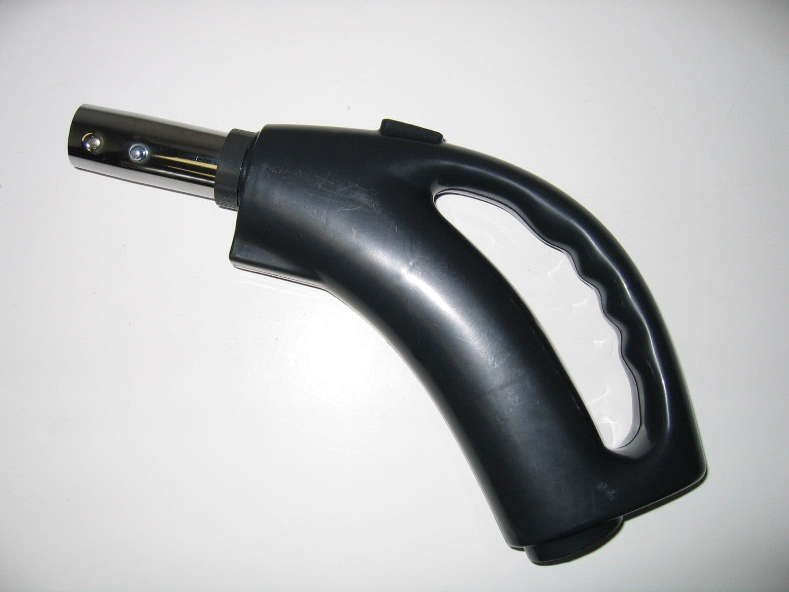
Click to zoom
Application Details
- Equipment Class
- DSC - Part 15 Security/Remote Control Transmitter
- Date of Grant
- May 10, 2005
- Application Purpose
- Original Equipment
- Date of Application
- May 10, 2005
- Equipment Note
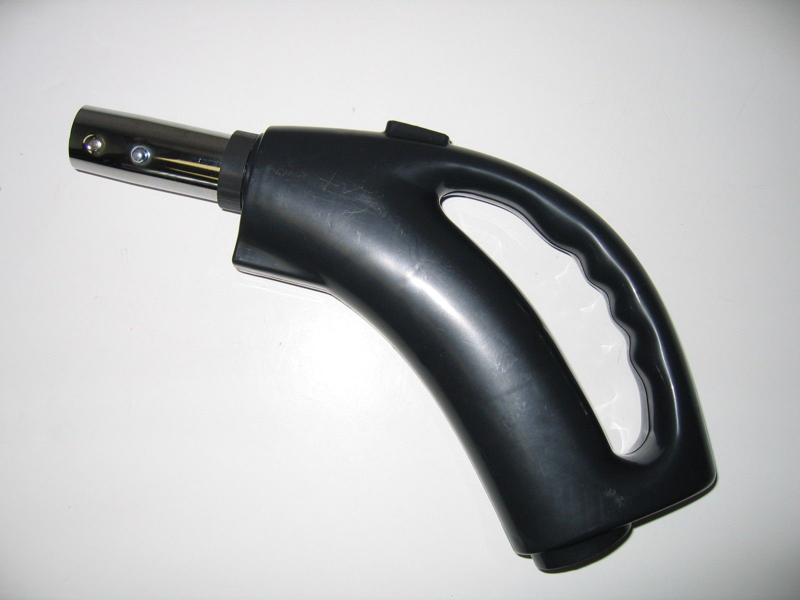
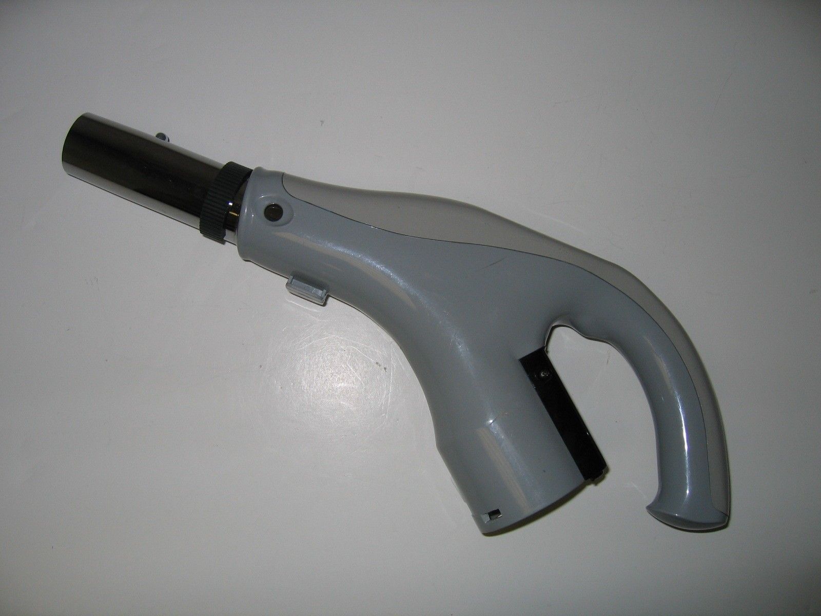
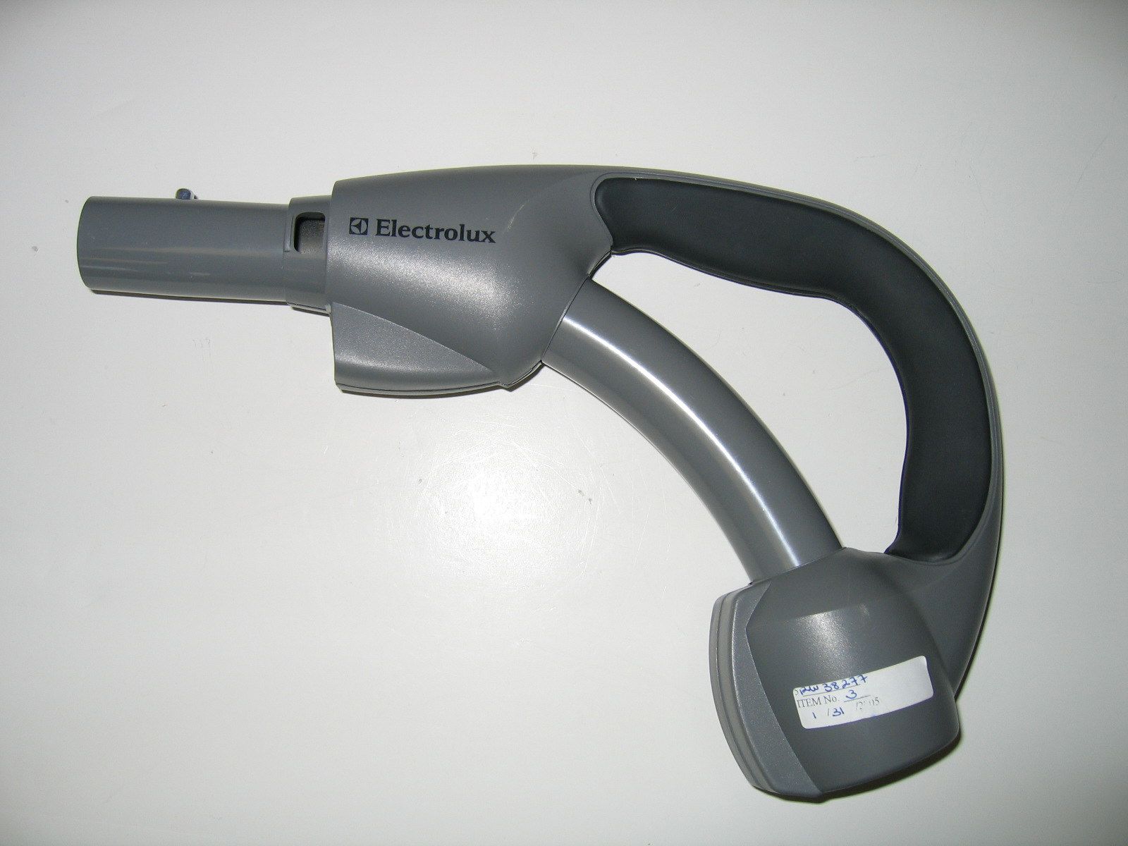
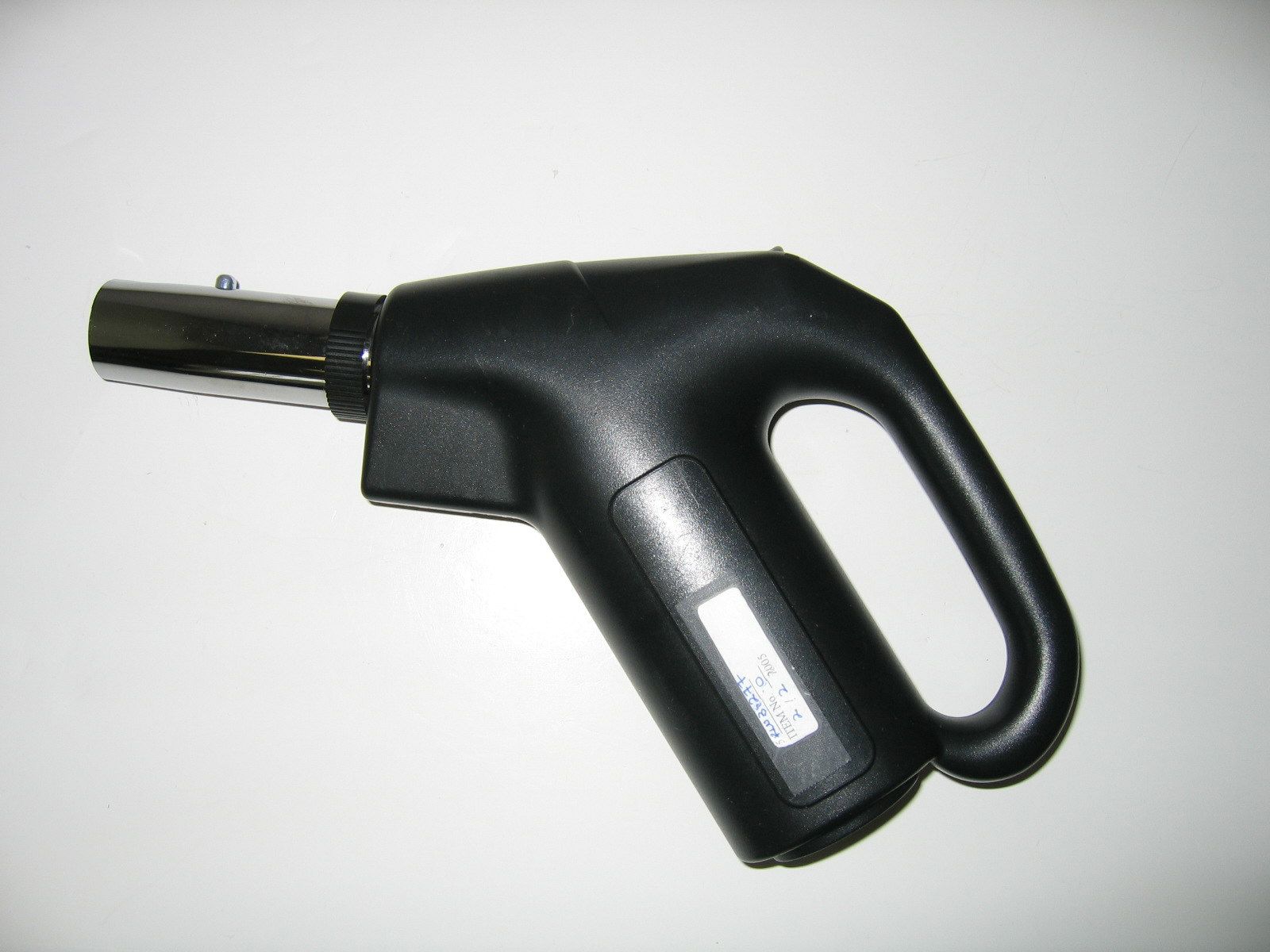
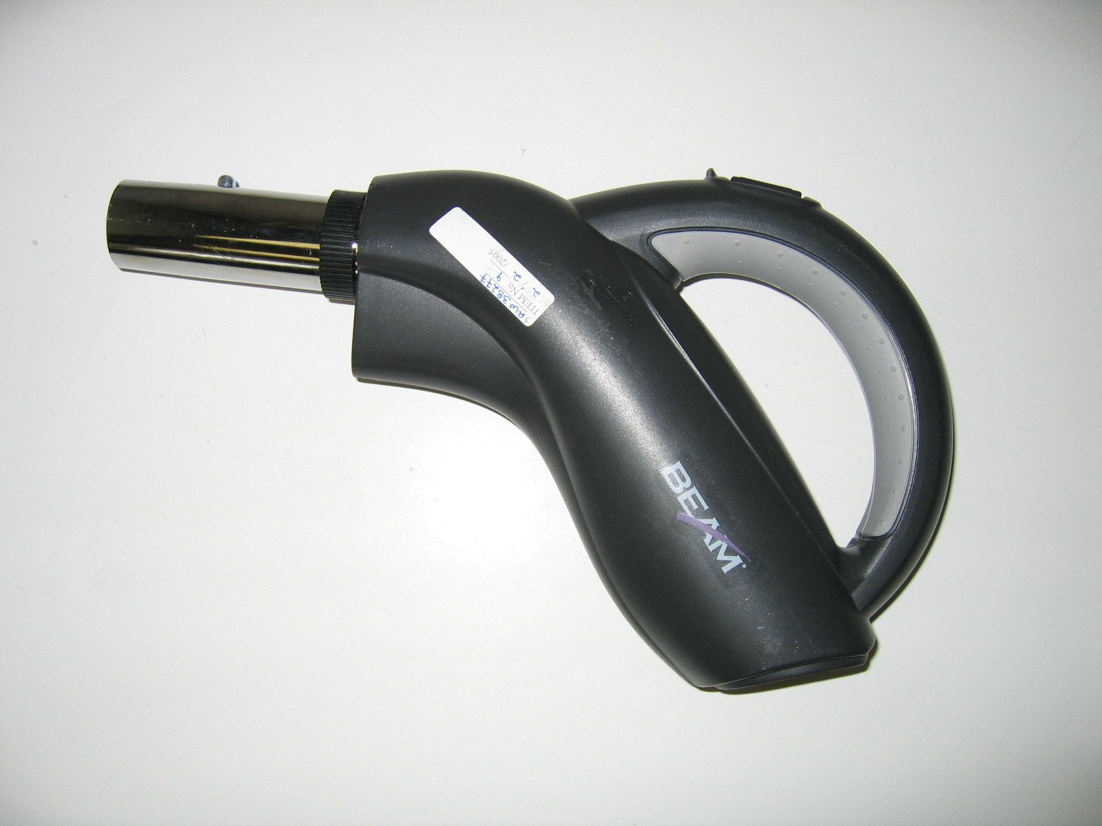
- Hose-handle RF Transmitter
- Frequency Range
- 433.92000000 - 433.92000000
- Company
- Alutron Modules Inc.
- Country
- Canada
Documents & Files
Document Text
Text extracted from the exhibit documents filed with the FCC. Open a document above to read the original.
Users Manual
Hose Handle RF Kit – LV9 Wireless Controller Installation Instructions 1.Remove low-voltage wires from central vacuum unit, if connected. 2.Install low-voltage wire jumpers (supplied) to the central vacuum unit. Install the other end of the jumper to the tabs on the LV9 Wireless Receiverlabelled “LV”. 3.Attach Velcro piece to the back of the LV9 and to a location suitable to support the LV9. Ensure the antenna is extended straight up from the top of the unit. Mount receiver at a minimum distance of 6 feet away from the central vacuum unit in order to prevent electrical interference of the RF signal from the motor. 4.Place the LV9 into position and insert connector end of the power adapter to the LV9 “24 Vac Input” terminal. 5.Turn power back on to central vacuum unit and plug AC adapter into power source. 6. To program the Hose Handle Transmitter :Press with a pointed object, the switch located on the top side of the LV9 Wireless Receiver. Immediately press and hold the “I” button located on the Hose Handle for 1 second. Programming is now complete. 7. Operation of the Transmitter:to turn on the central vacuum unit, press the “I” button located on the transmitter. To turn off, press the “O” button. Caution: Disconnect power to central vacuum system before starting Part Nbr: 980 INS-003 Rev 1.2April 2005 NOTE:Changes or modifications not expressly approved by Alutron Modules could void the user's authority to operate the equipment. Hose Handle RF Kit – LV9 Wireless Controller Installation Instructions 1.Remove low-voltage wires from central vacuum unit, if connected. 2.Install low-voltage wire jumpers (supplied) to the central vacuum unit. Install the other end of the jumper to the tabs on the LV9 Wireless Receiverlabelled “LV”. 3.Attach Velcro piece to the back of the LV9 and to a location suitable to support the LV9. Ensure the antenna is extended straight up from the top of the unit. Mount receiver at a minimum distance of 6 feet away from the central vacuum unit in order to prevent electrical interference of the RF signal from the motor. 4.Place the LV9 into position and insert connector end of the power adapter to the LV9 “24 Vac Input” terminal. 5.Turn power back on to central vacuum unit and plug AC adapter into power source. 6. To program the Hose Handle Transmitter :Press with a pointed object, the switch located on the top side of the LV9 Wireless Receiver. Immediately press and hold the “I” button located on the Hose Handle for 1 second. Programming is now complete. 7. Operation of the Transmitter:to turn on the central vacuum unit, press the “I” button located on the transmitter. To turn off, press the “O” button. Caution: Disconnect power to central vacuum system before starting Part Nbr: 980 INS-003 Rev 1.2April 2005 NOTE:Changes or modifications not expressly approved by Alutron Modules could void the user's authority to operate the equipment.
Users Manual
Hose Handle RF Kit - Wireless Controller – LV11 Installation Instructions 1.Remove low-voltage wires from central vacuum unit, if connected. 2.Install low-voltage wire jumpers (supplied) to the central vacuum unit. Install the other end of the wire jumper to the tabs on the LV11 Wireless Receiverlabelled “LV”. 3.Mount the LV11 in a suitable location. Ensure the antenna is extended straight up from the top of the unit. Mount receiver at a minimum distance of 6 feet away from the central vacuum unit in order to prevent electrical interference of the RF signal from the motor. 4.Insert connector end of the power adapter to the LV11 “9 Vac Input”terminal. 5.Turn power back on to central vacuum unit and plug AC adapter into power source. 6. To program the Hose Handle Transmitter :Press, with a pointed object, the switch located on the top side of the LV11 Wireless Receiver. Immediately press and hold the right side of the rocker switch located on the Hose Handle for 1 second. Programming is now complete. 7. Operation of the Transmitter: to turn on the central vacuum unit, press the right side of the rocker switch located on the Hose Handle. To turn off, press the left side of the rocker switch on the Hose Handle. Caution: Disconnect power to central vacuum system before starting Part Nbr: 980 INS-004 Rev 1.1April 2005 NOTE:Changes or modifications not expressly approved by Alutron Modules could void the user's authority to operate the equipment. Hose Handle RF Kit - Wireless Controller – LV11 Installation Instructions 1.Remove low-voltage wires from central vacuum unit, if connected. 2.Install low-voltage wire jumpers (supplied) to the central vacuum unit. Install the other end of the wire jumper to the tabs on the LV11 Wireless Receiverlabelled “LV”. 3.Mount the LV11 in a suitable location. Ensure the antenna is extended straight up from the top of the unit. Mount receiver at a minimum distance of 6 feet away from the central vacuum unit in order to prevent electrical interference of the RF signal from the motor. 4.Insert connector end of the power adapter to the LV11 “9 Vac Input”terminal. 5.Turn power back on to central vacuum unit and plug AC adapter into power source. 6. To program the Hose Handle Transmitter :Press, with a pointed object, the switch located on the top side of the LV11 Wireless Receiver. Immediately press and hold the right side of the rocker switch located on the Hose Handle for 1 second. Programming is now complete. 7. Operation of the Transmitter: to turn on the central vacuum unit, press the right side of the rocker switch located on the Hose Handle. To turn off, press the left side of the rocker switch on the Hose Handle. Caution: Disconnect power to central vacuum system before starting Part Nbr: 980 INS-004 Rev 1.1April 2005 NOTE:Changes or modifications not expressly approved by Alutron Modules could void the user's authority to operate the equipment.
Cover Letter(s)
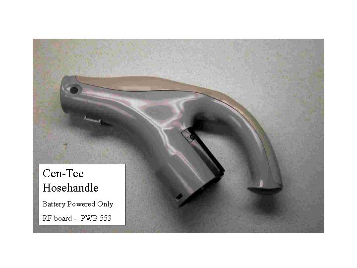
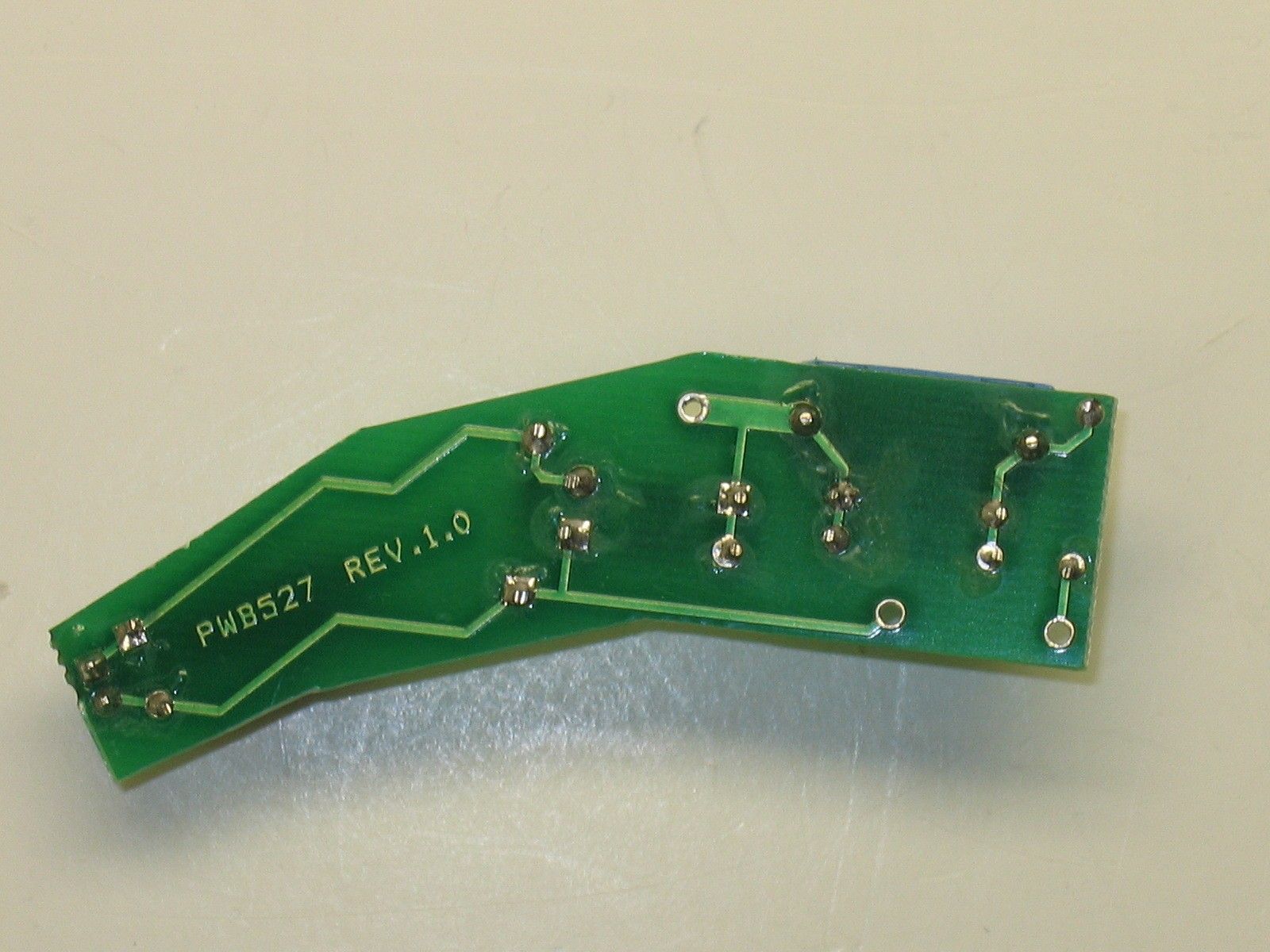
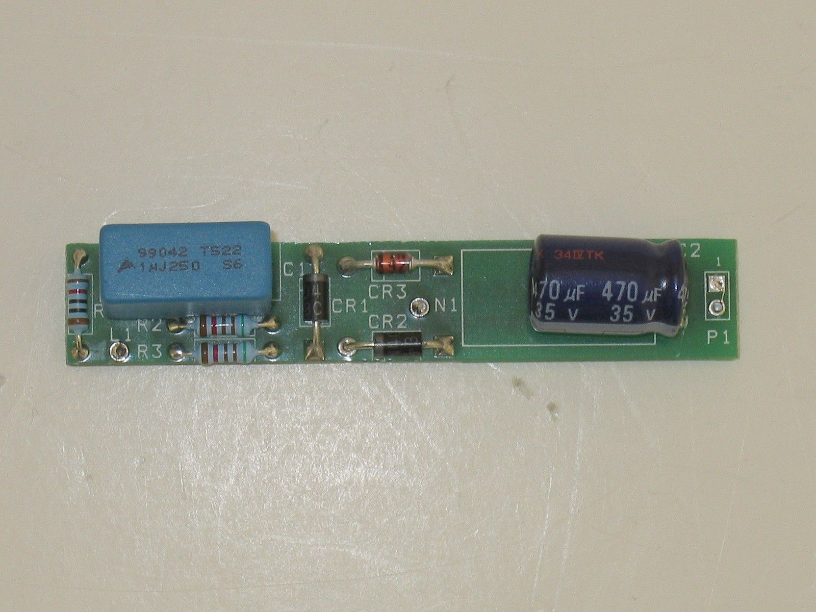
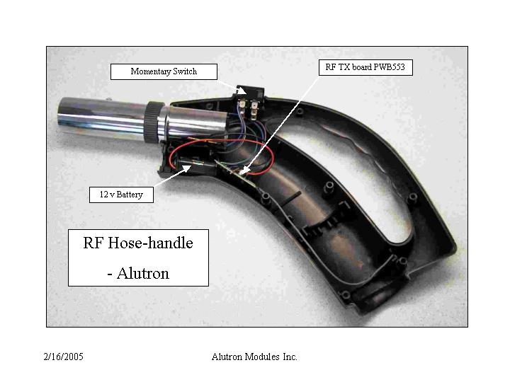
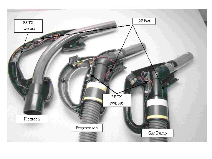
Alutron Modules Inc 420 Industrial Parkway South, Aurora Power Excellence Ltd. Ontario, CANADA L4G 3V7 allenm Page 1 5/11/2005 RF transmitting hose-handles – component details (Rev 1) Hose-handle Type RF transmitter board AC power board B=battery; AC=line power Layout gerber schematic Layout gerber Schematic Flextech B PWB553 MCP553 Flextech AC PWB553 MCP553 PWB527 MCP527 Progression B PWB550 MCP550 Progression AC PWB550 MCP550 PWB527 MCP527 Gas Pump B PWB550 MCP550 Gas Pump AC PWB550 MCP550 PWB551 MCP551 Cen-Tec PWB553 MCP553 Alutron PWB553 MCP553
Cover Letter(s)
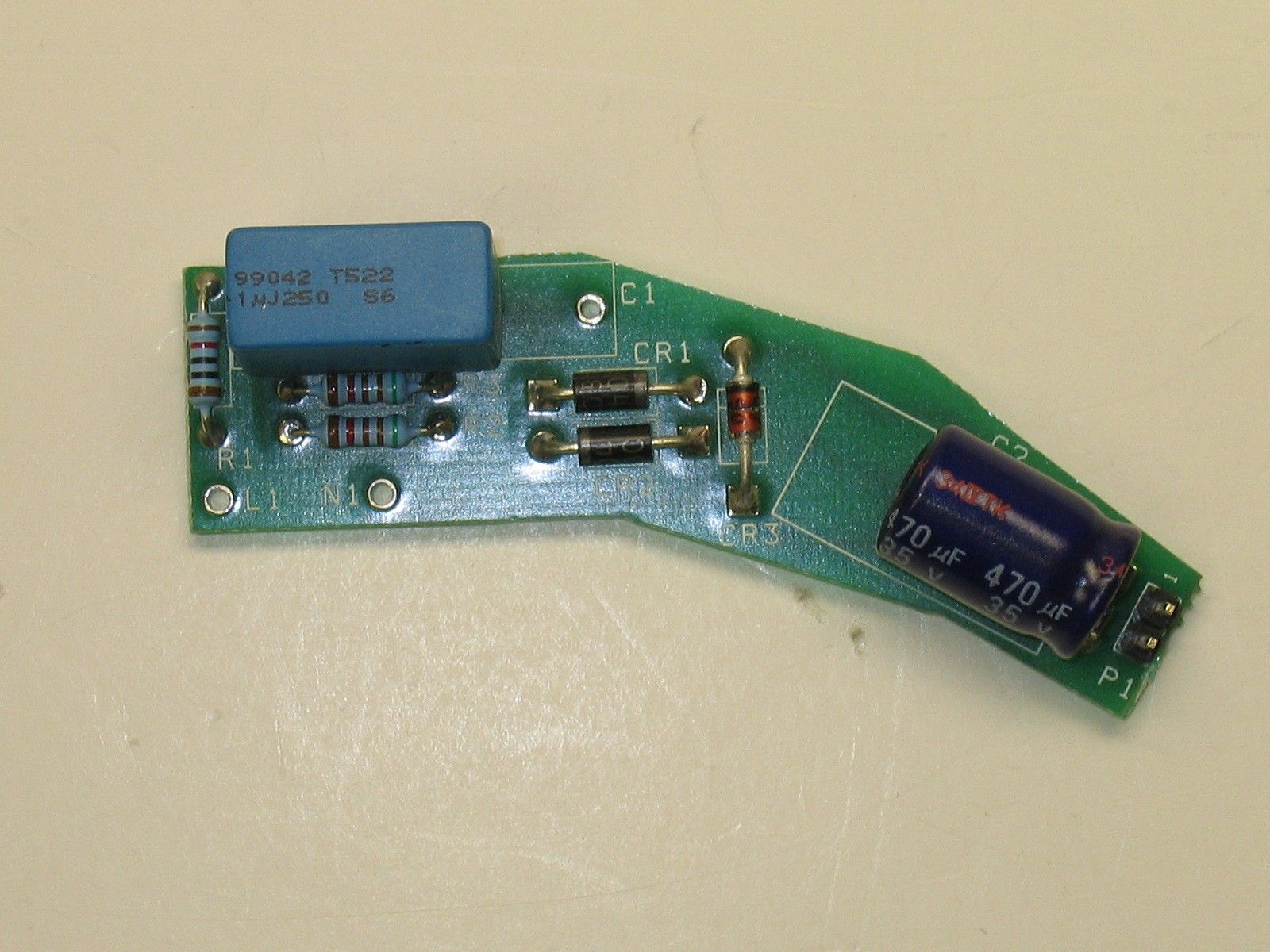
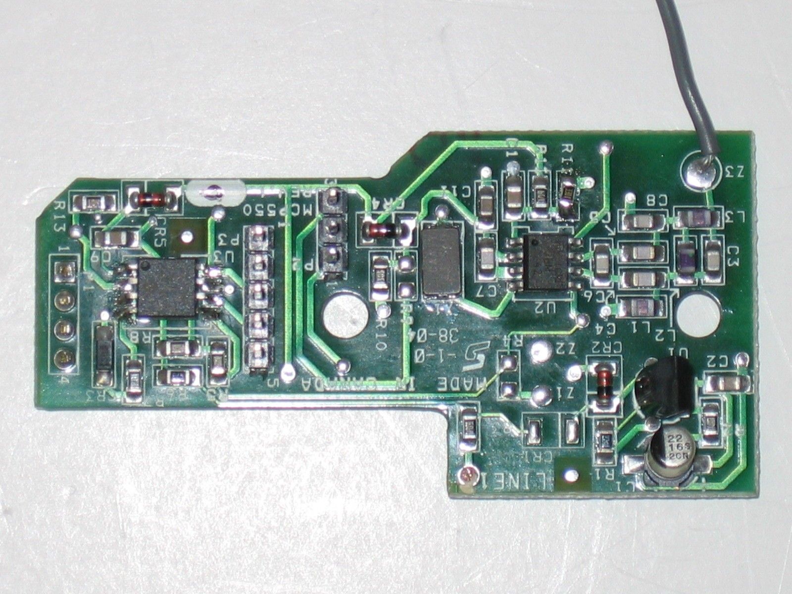
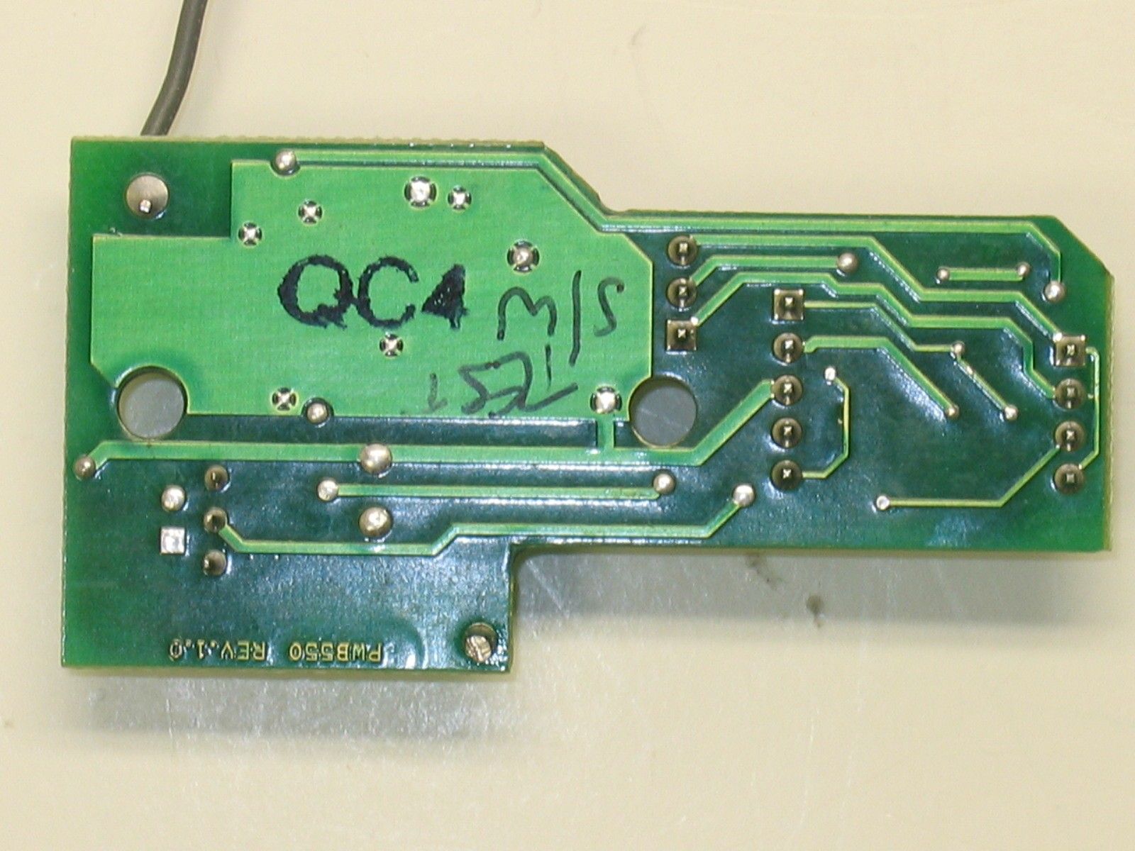
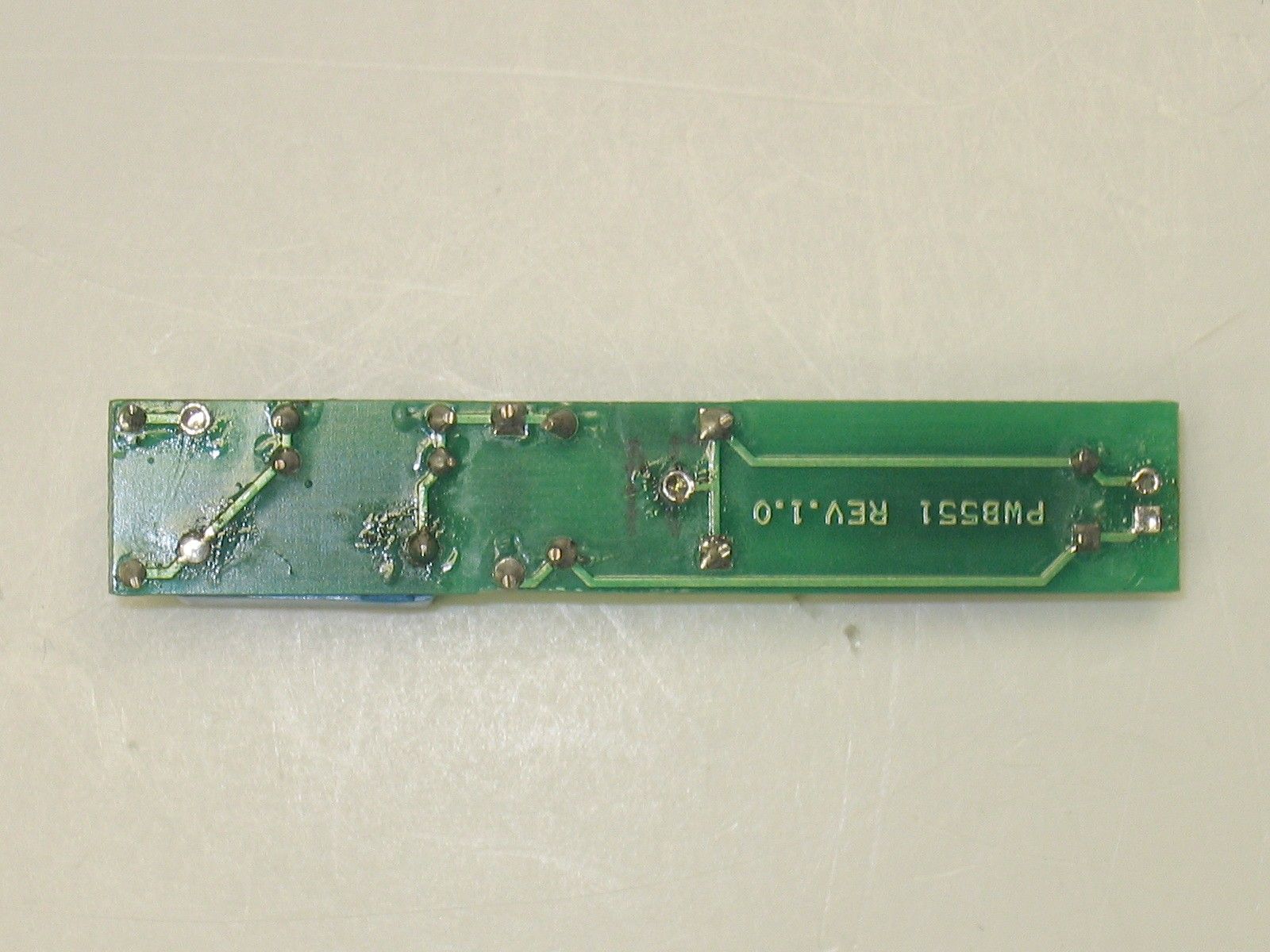
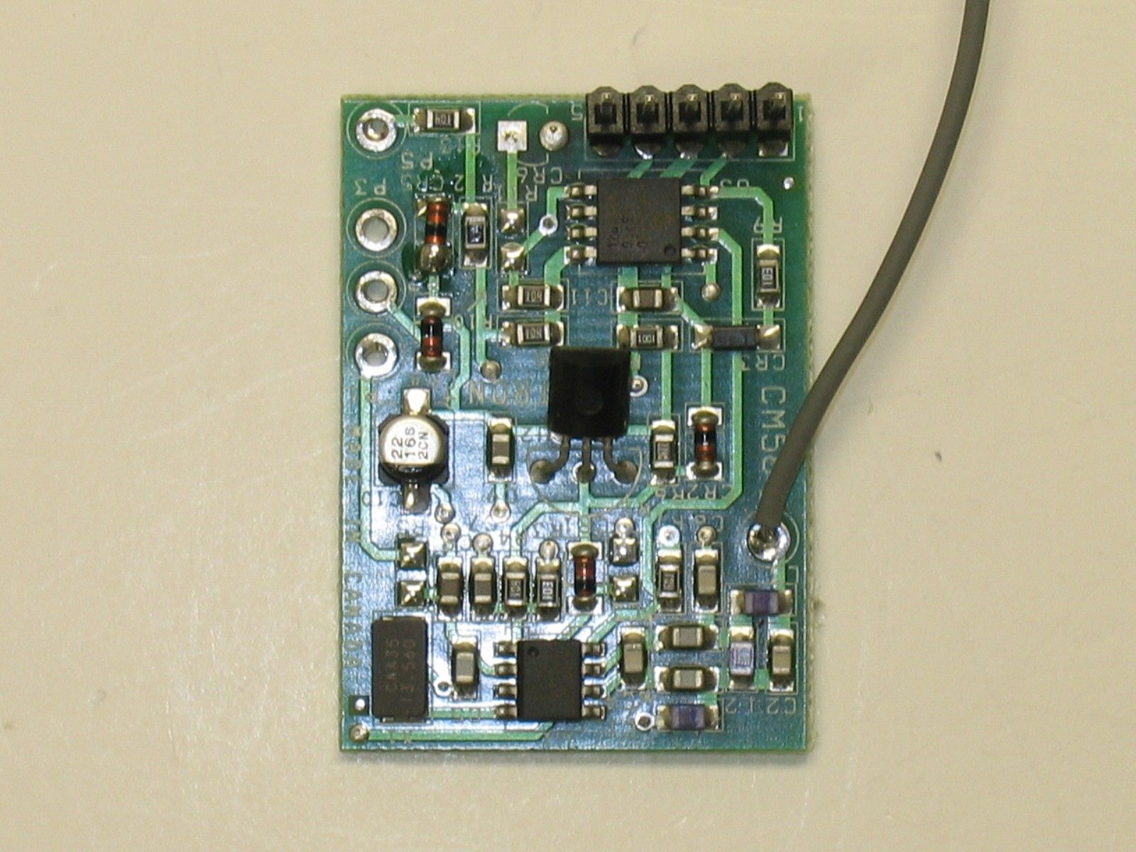
Alutron Modules Inc 420 Industrial Parkway South, Aurora Power Excellence Ltd. Ontario, CANADA L4G 3V7 Hose-handle RF Transmitter family (HHRFT) Circuit Comparisons The following table lists the RF transmitter boards used in each member of the HHRFT family of vacuum hose-handle transmitters: Description RF transmitter board HHRFT RFT Model # B=battery; AC=line power Layout gerber schematic FB Flextech B PWB553 MCP553 FA Flextech AC PWB553 MCP553 PB Progression B PWB550 MCP550 PA Progression AC PWB550 MCP550 GB Gas Pump B PWB550 MCP550 GA Gas Pump AC PWB550 MCP550 CB Cen-Tec B PWB553 MCP553 AB Alutron B PWB553 MCP553 As can be seen there are two different circuit configurations used and these are compared as follows: • Electronic Circuit designs MCP553 and MCP550 The schematic diagrams for these designs are essentially identical. Their respective Bills of Materials differ only in the orientation of the connectors used for in-circuit programming of the microcontroller. • Printed Wiring Board layouts PWB 553 and PWB550 In order to accommodate the differing cavity dimensions within the various handles it was necessary to produce two different shaped boards. The orientation of the RF generation and transmission circuitry is identical between the two. The distance between the microcontroller circuitry and the RF sections of the boards is different with this being marginally larger in the case of PWB550 thereby producing a longer, narrower form factor compared to PWB553.
ID Label/Location Info
Alutron Modules Inc 420 Industrial Parkway South, Aurora Power Excellence Ltd. Ontario, CANADA L4G 3V7 RF Certification Label Placement on Hose-handle Transmitter Product Family HHRFT all models FCC ID: S3PHHRFT Industry Canada: 4603A-0501 Label Format: Model No.: RFT-XX Made In Canada IC: 4603A-0501 FCC ID: S3PHHRFT This device complies with Part 15 of the FCC Rules. Operation is subject to the following two conditions: (1) This device may not cause harmful interference, and (2) This device must accept any interference received, including interference that may cause undesired operation. Handle Side View Adhesive Label on undersurface
Test Report
Master:PT15-Sub-C-15231 Date: November 12, 2001 Test Report: 5W38277 Applicant: Alutron Modules Inc. Power Excellence Ltd. 420 Industrial Parkway South Aurora, Ontario L4G 3V7 Equipment Under Test: Vacuum Hose Handle RF Transmitter (EUT) Models RFT-FB and RFT-FA RFT-PB and RFT-PA RFT-GB and RFT-GA Cen-Tec Alutron Accordance With: FCC Part 15, Subpart C, 15.231 Tested By: Nemko Canada Inc. 303 River Road, R.R. 5 Ottawa, Ontario K1V 1H2 Authorized By: Sim Jagpal, Resource Manager Date: 5 May 2005 Total Number of Pages: 31 Nemko Canada Inc. FCC PART 15, SUBPART C, 15.231 PROJECT NO.: 5W38277 EQUIPMENT: Vacuum Hose Handle RF Transmitter Page 2 of 31 Table of Contents Section 1. Summary of Test Results ...................................................................................... 3 Section 2. Equipment Under Test .......................................................................................... 5 Section 3. Transmission Requirements ................................................................................. 7 Section 4. Radiated Emissions ................................................................................................ 9 Section 5. Occupied Bandwidth ........................................................................................... 20 Section 6. Powerline Conducted Emissions......................................................................... 22 Section 7. Block Diagrams .................................................................................................... 30 Section 8. Test Equipment List ............................................................................................ 31 Nemko Canada Inc. FCC PART 15, SUBPART C, 15.231 PROJECT NO.: 5W38277 EQUIPMENT: Vacuum Hose Handle RF Transmitter Page 3 of 31 Section 1. Summary of Test Results General All measurements are traceable to national standards. These tests were conducted on a sample of the equipment for the purpose of demonstrating compliance with Part 15, Subpart C. All tests were conducted using measurement procedure ANSI C63.4-2003. Radiated emissions are made on an open area test site. A description of the test facility is on file with the FCC. THIS TEST REPORT RELATES ONLY TO THE ITEM(S) TESTED. THE FOLLOWING DEVIATIONS FROM, ADDITIONS TO, OR EXCLUSIONS FROM THE TEST SPECIFICATIONS HAVE BEEN MADE. See “ Summary of Test Data”. TESTED BY: DATE: February 18, 2005 Nemko Canada Inc. authorizes the above named company to reproduce this report provided it is reproduced in its entirety and for use by the company’s employees only. Any use which a third party makes of this report, or any reliance on or decisions to be made based on it, are the responsibility of such third parties. Nemko Canada Inc. accepts no responsibility for damages, if any, suffered by any third party as a result of decisions made or actions based on this report. This report applies only to the items tested. Nemko Canada Inc. FCC PART 15, SUBPART C, 15.231 PROJECT NO.: 5W38277 EQUIPMENT: Vacuum Hose Handle RF Transmitter Page 4 of 31 Summary Of Test Data Name of Test Para. Number Results Transmission Requirements 15.231(a) Complies Radiated Emissions 15.231(b) Complies Occupied Bandwidth 15.231(c) Complies Frequency Tolerance 15.231(d) N/A Periodic Alternate Field Strength Requirements 15.231(e) N/A Powerline Conducted Emissions 15.207 Complies Test Conditions: Standard Test Voltage Battery Powered Units: 12 Volt Battery Type 23A AC Powered Units: 120 VAC, 60 Hz Indoor Temperature: 21.4°C Humidity: 17.4% Outdoor Temperature: 7.4°C Humidity: 27.3% Nemko Canada Inc. FCC PART 15, SUBPART C, 15.231 PROJECT NO.: 5W38277 EQUIPMENT: Vacuum Hose Handle RF Transmitter Page 5 of 31 Section 2. Equipment Under Test General Equipment Information Manufacturer: Alutron Modules Inc. Model No.: RFT-FB and RFT-FA RFT-PB and RFT-PA RFT-GB and RFT-GA Cen-Tec Alutron Date Received In Laboratory: Jan 31, 2005 Transmitter: 433.92 MHz ± 100 kHz Type of Transmission: On Off Keying using Pulse Width Modulation Primary Power Requirement: AC Units: 120 VAC, 60 Hz Battery Powered Units: Type 12 Volt Battery Type 23A Type of Equipment and Model Differences: The equipment tested is a vacuum hose handle RF transmitter used to remotely control a central vacuum cleaner system. All models are installed inside a vacuum hose handle and use a permanently attached antenna consisting of wire soldered to PCB. See attached list of model differences. All models use one of two basic types of PCB, PWB553 or PWB550. Both PCB’s use identical RF and base band circuits with only minor differences in layout. The AC powered units use a separate AC power board with plug connector. Nemko Identification No.: Item 3 Unit 1 RFT-FB Item 8 Unit 2 RFT-FA Item 4 Unit 3 RFT-PB Item 9 Unit 4 RFT PA Item 5 Unit 5 RFT-GB Item 10 Unit 6 RFT-GA Item 12 Unit 7 Cen-Tec Item 13 Unit 8 Alutron Nemko Canada Inc. FCC PART 15, SUBPART C, 15.231 PROJECT NO.: 5W38277 EQUIPMENT: Vacuum Hose Handle RF Transmitter Page 6 of 31 Model Differences Hose-handle Type RF transmitter board AC power board B=battery; AC=line power Layout gerber schematic Layout gerber Schematic Flextech B PWB553 MCP553 Flextech AC PWB553 MCP553 PWB527 MCP527 Progression B PWB550 MCP550 Progression AC PWB550 MCP550 PWB527 MCP527 Gas Pump B PWB550 MCP550 Gas Pump AC PWB550 MCP550 PWB551 MCP551 Cen-Tec PWB553 MCP553 Alutron PWB553 MCP553 Nemko Canada Inc. FCC PART 15, SUBPART C, 15.231 PROJECT NO.: 5W38277 EQUIPMENT: Vacuum Hose Handle RF Transmitter Page 7 of 31 Section 3. Transmission Requirements Para. No.: 15.231(a) Test Performed By: Russell Grant Date of Test: Feb. 16, 05 Minimum Standard: 15.231(a) Continuous transmissions such as voice, video or data transmissions are not permitted. 15.231(a)(1) A manually operated transmitter shall employ a switch that will automatically deactivate the transmitter within not more than 5 seconds after being released. 15.231(a)(2) A transmitter activated automatically s…
Text truncated - open the document above for the full version.
Test Setup Photos
Nemko Canada Inc. FCC PART 15, SUBPART C, 15.231 PROJECT NO.: 5W38277 EQUIPMENT: Vacuum Hose Handle RF Transmitter Page 29 of 31 Conducted Emission Test Setup
Test Setup Photos
Nemko Canada Inc. FCC PART 15, SUBPART C, 15.231 PROJECT NO.: 5W38277 EQUIPMENT: Vacuum Hose Handle RF Transmitter Page 19 of 31 Radiated Emission Test Set Up Photograph
Contact Information
Applicant
Dan Paul(Engineering Manager)
Technical Contact
Alutron Modules Inc.Allen Muirhead
[email protected]905-727-8788
420 Industrial Parkway S. · Aurora, Ontario · Canada
Test Firm
Nemko Canada Inc. (Ottawa)Charles Neal
Technical Specifications
| # | Rule Parts | Frequency Range | Power Output |
|---|---|---|---|
| 1 | 15.231 | 433.92 MHz - 433.92 MHz | - |
Other Applications from Alutron Modules Inc.
S3PCM91
Jun 17, 2008Two Way Wireless Transceiver Module
Equipment Class
DTS - Digital Transmission System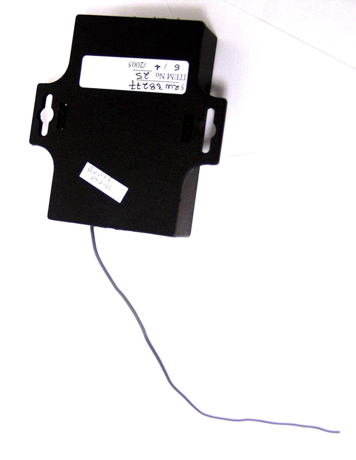
S3PRFR
Aug 25, 2005Central Vacuum Remote Control Receiver
Equipment Class
CYY - Communications Receiver used w/Pt 15 Transmitter