S4LGO500GPS Tracking System
TomTom International BV
Click to zoom
Application Details
- Equipment Class
- DSS - Part 15 Spread Spectrum Transmitter
- Date of Grant
- Jun 13, 2005
- Application Purpose
- Original Equipment
- Date of Application
- Jun 13, 2005
- Equipment Note
- GPS Tracking System
- Frequency Range
- 2402.00000000 - 2480.00000000
- Company
- TomTom International BV
- Country
- Netherlands
Documents & Files
Document Text
Text extracted from the exhibit documents filed with the FCC. Open a document above to read the original.
Users Manual
3 UK 3 TomTom GO Quick Start Guide UK DK NL FI FR DE IT NO PT ES SE Contents What's in the box? 4 Unpacking 4 Your TomTom GO 5 Remote control 6 Docking shoe 6 Installation 7 Assembly 7 Switching on for the first time 8 Starting up 8 Using TomTom GO 8 Using the remote control 9 How to plan your first route 10 Helping with your journey 12 What's on the screen? 13 Finding alternative routes 14 Advanced planning 15 Preferences 16 Use night colours 16 Manage POI 17 Hide POI 17 Change Home location 17 THE SMART CHOICE IN PERSONAL NAVIGATION Connecting to your phone 18 More information 20 TomTom PLUS 20 General information 20 4 UK 4 Unpacking Unpack your TomTom GO box and identify the contents. The model number of your TomTom GO can be found on the bottom of the device itself. You should have: • TomTom GO (1). Its main features are a touch-sensitive LCD screen, a power (On/ Off) button, a release button (for removing TomTom GO from its cradle) and a Secure Digital (SD) memory card slot (included in GO 500 and GO 300 models). • A pre-installed SD card (2) (included with GO 500 and GO 300 models). The GO 700 includes a pre-installed hard disk. • The component parts (3/4) of a suction-mount cradle, for attaching to your windscreen. • A DC power lead (5), with 12V cigarette lighter adaptor. This is the normal way of pro- viding power to TomTom GO when it’s in your vehicle. • An installation poster (6), showing how to assemble the cradle, how to fix it to your windscreen and how to insert TomTom GO. • A carry case (7), for storing TomTom GO when it’s not in your vehicle. • A USB data cable (8) for connecting TomTom GO to a Windows PC or Mac. • A Microsoft ® Windows ® and Mac ® compatible CD (9) containing documentation and optional extras. • A Product Code Card (10) for product activation, support and future map upgrades. • This Quick Start Guide (11). • An AC adaptor (12) , included for you to char- ge and work with TomTom GO even when it’s not in your vehicle (included with GO 700 and GO 500 models). Note that this comes with several international pin adaptors, for use any- where in the world. When you use the adaptor, please make sure it is cooled by placing it in a ventilated area. • A remote control (13) (included with GO 700 model), for operating TomTom GO when out of reach. This is available as an accessory for GO 700 and GO 500 models. What's in the box? 1 1 6 7 8 9 5 2 3 4 2 3 4 5 7 8 9 10 11 12 13 6 5 UK 5 What's in the box? NOTE: Do not expose TomTom GO to high or low temperatures. We recommend that you do not leave TomTom GO in direct sunlight for long periods or in an unattended car on sunny days. High or low temperatures can cause permanent damage. Do not attempt to service TomTom GO yourself! Do not open, puncture or disassemble it. Doing so may be dangerous and will invalidate your warranty. Do not leave your TomTom GO in your glove box when driving. � � � � � � � � � � � � � � � � � �� �� � Your TomTom GO 1. Touchscreen 2. SD card slot (included on GO 500 and GO 300 models) 3. Release button 4. On/Off button 5. Charging LED 6. Speaker 7. AC-connector 8. USB-connector 9. Docking connector 6 UK 6 What's in the box? � � � � � � � � � � � � � � � � � � � � Docking Shoe 1. Integrated microphone (included with GO 700 and GO 500 models). 2. Charger socket 3. External microphone socket Remote control 1. Volume up/down 2. OK button 3. Arrow buttons 4. Left and Right soft buttons 5. Keyboard button 6. Batteries 7. Battery compartment � � � � � � � � � � � � � � � � � � � � 7 UK SE 7 Assembly 1. Assemble the suction-mount cradle as shown in the installation poster. 2. Plug the small plug end of the DC power lead into the socket on the back of the cradle. Plug the other end into your vehicle’s 12V (cigarette lighter) socket. 3. Ease TomTom GO onto its cradle by locating its front edge first and then rotating back firmly until you hear a click. You’ll feel TomTom GO lock into place. The green LED on TomTom GO’s front panel will light up if the cradle is also connected to your vehicle’s 12V socket. 4. Clean the inside of your windscreen (or side window), to remove any dust and grease. Place the cradle in a suitable location on your windscreen and push the black plastic lever to the right, fixing the cradle in position. NOTE: Some newer vehicles may have a heat reflec- tive shield embedded in the windscreen. In some cases this can prevent proper GPS signal reception. If this turns out to be a problem in your vehicle, you will need to purchase and install the TomTom External Antenna Kit (available as an accessory). Tip:You don’t have to use the cradle if you don’t want to. If necessary, TomTom GO can be positioned on its own anywhere that’s convenient, provided that it’s safely secured. Under normal journey conditions, the suction mount is perfectly sufficient to hold the cradle in position. Note that suction may be lost if left overnight, due to condensation and low Installation temperature. For this reason, and for security, we recommend removing both the suction mount cradle and TomTom GO when leaving your vehicle overnight. To remove the cradle, pull the suction mount lever to the left. If the cradle still doesn’t detach from your wind- screen, tug gently on the clear plastic tab at the edge of the suction mount, to break the vacuum seal. Tip: To activate your 12V socket, you may need to set your ignition key in an ‘Accessories’ position. Please consult your vehicle handbook. In addition, TomTom GO contains a rechargeable battery and can be used for up to 4 hours without charging, so for short journeys it may be possible to do without the DC power lead for simpler and tidier operation. To adjust the angle of TomTom GO, slacken the adjustable knobs on the cradle and then turn it gently. In addition to tilting the cradle up and down and from side to side, you can also rotate TomTom GO in the cradle, from left to right, ±45°. When you’re happy, tighten up the knobs again. Tip: After using TomTom G…
Text truncated - open the document above for the full version.
Cover Letter(s)
TomTom BV. Rembrandtplein 35, 1017 CT Amsterdam, The Netherlands Confidentiality Request Pursuant to Sections 0.457 and 0.459 of the Commission's Rules, the Appli Hereby requests confidential treatment of information applied this As outlined below: 1. Schematic 2. Block Diagram 3. Operation Description The above materials contain trade secrets and proprietary information not customarily Released to the public. The public disclosure of these matters might be harmful to the Applicant and provide unjustified benefits to its competitors. The Applicant understands that pursuant to Rule 0.457, disclosure of this Application and all accompanying documentation will not be made before the date of the Grant for this application 13 May 2005 Federal Communications Commission Authorization and Evaluation Division FCC ill : S4LGOSOO Sincerely, M TomTom BV. Rembrandtplein 35, 1017 CT Amsterdam, Tel: + 31 (0)20 8500800 FAX: + 31 (0)208501099 E-mail: [email protected] TomTom BV Rembrandtplein 35 1017 CT AMSTERDAM The Netherlands t: + 31 (0) 20 850 08 00 f: + 31 (0) 20 8501099 TOt1)Tom Inc. 150 Baker Ave CONCORD MA 01742 United States of America t: +1 9782879555 f: +1 978 287 95 22 cant Application The Netherlands Rabobank Amsterdam no: 393782 832 Swiftcode: RABONL2U Iban no: NL04RABO039782832 VAT no: NL-800765679 B01 e: [email protected] www.tomtom.com TomTom Software Ltd. 5 Huntsworth Mews LONDON NW1 6DE United Kingdom t: + 44 (0) 20 7563 7300 f: + 44 (0) 20 7563 7301
External Photos
SPORTON International Inc. PAGE NUMBER : A1 OF A17 TEL : 886-2-2696-2468 ISSUED DATE : May,19,2005 FAX : 886-2-2696-2255 APPENDIX A. Photographs of EUT SPORTON International Inc. PAGE NUMBER : A14 OF A17 TEL : 886-2-2696-2468 ISSUED DATE : May,19,2005 FAX : 886-2-2696-2255 SPORTON International Inc. PAGE NUMBER : A15 OF A17 TEL : 886-2-2696-2468 ISSUED DATE : May,19,2005 FAX : 886-2-2696-2255 SPORTON International Inc. PAGE NUMBER : A16 OF A17 TEL : 886-2-2696-2468 ISSUED DATE : May,19,2005 FAX : 886-2-2696-2255 SPORTON International Inc. PAGE NUMBER : A17 OF A17 TEL : 886-2-2696-2468 ISSUED DATE : May,19,2005 FAX : 886-2-2696-2255
ID Label/Location Info
Label Location
Internal Photos
SPORTON International Inc. PAGE NUMBER : A7 OF A15 TEL : 886-2-2696-2468 ISSUED DATE : May 9, 2005 FAX : 886-2-2696-2255 SPORTON International Inc. PAGE NUMBER : A8 OF A15 TEL : 886-2-2696-2468 ISSUED DATE : May 9, 2005 FAX : 886-2-2696-2255 SPORTON International Inc. PAGE NUMBER : A9 OF A15 TEL : 886-2-2696-2468 ISSUED DATE : May 9, 2005 FAX : 886-2-2696-2255 SPORTON International Inc. PAGE NUMBER : A10 OF A15 TEL : 886-2-2696-2468 ISSUED DATE : May 9, 2005 FAX : 886-2-2696-2255 SPORTON International Inc. PAGE NUMBER : A11 OF A15 TEL : 886-2-2696-2468 ISSUED DATE : May 9, 2005 FAX : 886-2-2696-2255 SPORTON International Inc. PAGE NUMBER : A12 OF A15 TEL : 886-2-2696-2468 ISSUED DATE : May 9, 2005 FAX : 886-2-2696-2255 SPORTON International Inc. PAGE NUMBER : A13 OF A15 TEL : 886-2-2696-2468 ISSUED DATE : May 9, 2005 FAX : 886-2-2696-2255 SPORTON International Inc. PAGE NUMBER : A14 OF A15 TEL : 886-2-2696-2468 ISSUED DATE : May 9, 2005 FAX : 886-2-2696-2255 SPORTON International Inc. PAGE NUMBER : A15 OF A15 TEL : 886-2-2696-2468 ISSUED DATE : May 9, 2005 FAX : 886-2-2696-2255
Test Report
FCC ID: S4LGO500 Issued on May 10, 2005 Report No.: FR533147 SPORTON International Inc. TEL : 886-2-2696-2468 FAX : 886-2-2696-2255 FCC TEST REPORT CATEGORY : Mobile PRODUCT NAME : GPS tracking system FCC ID. : S4LGO500 FILING TYPE : Certification BRAND NAME : TomTom MODEL NAME : GO 500 APPLICANT : TomTom BV. Rembrandtplein 35 1017 CT Amsterdam The Netherlands MANUFACTURER : Inventec Appliances Corp. 37, Wugung 5th, Rd., Wugu Shiang, Taipei, Taiwan ISSUED BY : SPORTON INTERNATIONAL INC. 6F, No. 106, Sec. 1, Hsin Tai Wu Rd., His Chih, Taipei Hsien, Taiwan, R.O.C. Statements: The test result in this report refers exclusively to the presented test model / sample. Without written approval of SPORTON International Inc., the test report shall not be reproduced except in full. Certificate or Test Report could not be used by the applicant to claim the product endorsement by CNLA and any agency of U.S. government. The test equipment used to perform the test is calibrated and traceable to NML/ROC or NIST/USA. 1190 ILAC MRA FCC ID: S4LGO500 Issued on May 10, 2005 Report No.: FR533147 SPORTON International Inc. Page No. : i TEL : 886-2-2696-2468 Issued Date : May 10, 2005 FAX : 886-2-2696-2255: Table of Contents HISTORY OF THIS TEST REPORT .....................................................................................................................II CERTIFICATE OF COMPLIANCE.......................................................................................................................III 1. GENERAL DESCRIPTION OF EQUIPMENT UNDER TEST...........................................................................1 1.1. Applicant ......................................................................................................................................................................................... 1 1.2. Manufacturer ................................................................................................................................................................................... 1 1.3. Basic Description of Equipment under Test.................................................................................................................................... 1 1.4. Features of Equipment under Test ................................................................................................................................................. 1 1.5. Table for Carrier Frequencies ......................................................................................................................................................... 2 2. TEST CONFIGURATION OF THE EQUIPMENT UNDER TEST .....................................................................3 2.1. Connection Diagram of Test System .............................................................................................................................................. 3 2.2. The Test Mode Description............................................................................................................................................................. 3 2.3. Description of Test Supporting Units .............................................................................................................................................. 4 3. GENERAL INFORMATION OF TEST ..............................................................................................................5 3.1. Test Facility ..................................................................................................................................................................................... 5 3.2. Standards for Methods of Measurement......................................................................................................................................... 5 3.3. Frequency Range Investigated ....................................................................................................................................................... 5 3.4. Test Distance .................................................................................................................................................................................. 5 3.5. Test Software .................................................................................................................................................................................. 5 4. LIST OF MEASUREMENTS .............................................................................................................................6 4.1. Summary of the Test Results.......................................................................................................................................................... 6 5. TEST RESULT ..................................................................................................................................................7 5.1. Test of Hopping Channel Bandwidth .............................................................................................................................................. 7 5.2. Test of Hopping Channel Separation............................................................................................................................................ 11 5.3. Test of Number of Hopping Frequency......................................................................................................................................... 15 5.4. Test of Dwell Time of Each Frequency ......................................................................................................................................... 17 5.5. Maximum Peak Output Power ...................................................................................................................................................... 24 5.6. Test of Band Edges Emission....................................................................................................................................................... …
Text truncated - open the document above for the full version.
Test Setup Photos
FCC ID: S4LGO500 Issued on May 10, 2005 Report No.: FR533147 SPORTON International Inc. Page No. : 33 of 47 TEL : 886-2-2696-2468 Issued Date : May 10, 2005 FAX : 886-2-2696-2255 5.7.8. Photographs of Conducted Emission Test Configuration FRONT VIEW REAR VIEW FCC ID: S4LGO500 Issued on May 10, 2005 Report No.: FR533147 SPORTON International Inc. Page No. : 40 of 47 TEL : 886-2-2696-2468 Issued Date : May 10, 2005 FAX : 886-2-2696-2255 5.8.11. Photographs of Radiated Emission Test Configuration FRONT VIEW REAR VIEW
Contact Information
Applicant
Barto Wijlens(Head of Global Supply chain)
Test Firm
SPORTON International IncKathy Lin
Technical Specifications
| # | Rule Parts | Frequency Range | Power Output |
|---|---|---|---|
| 1 | 15C | 2.40 GHz - 2.48 GHz | 1.00 mW |
Other Applications from TomTom International BV
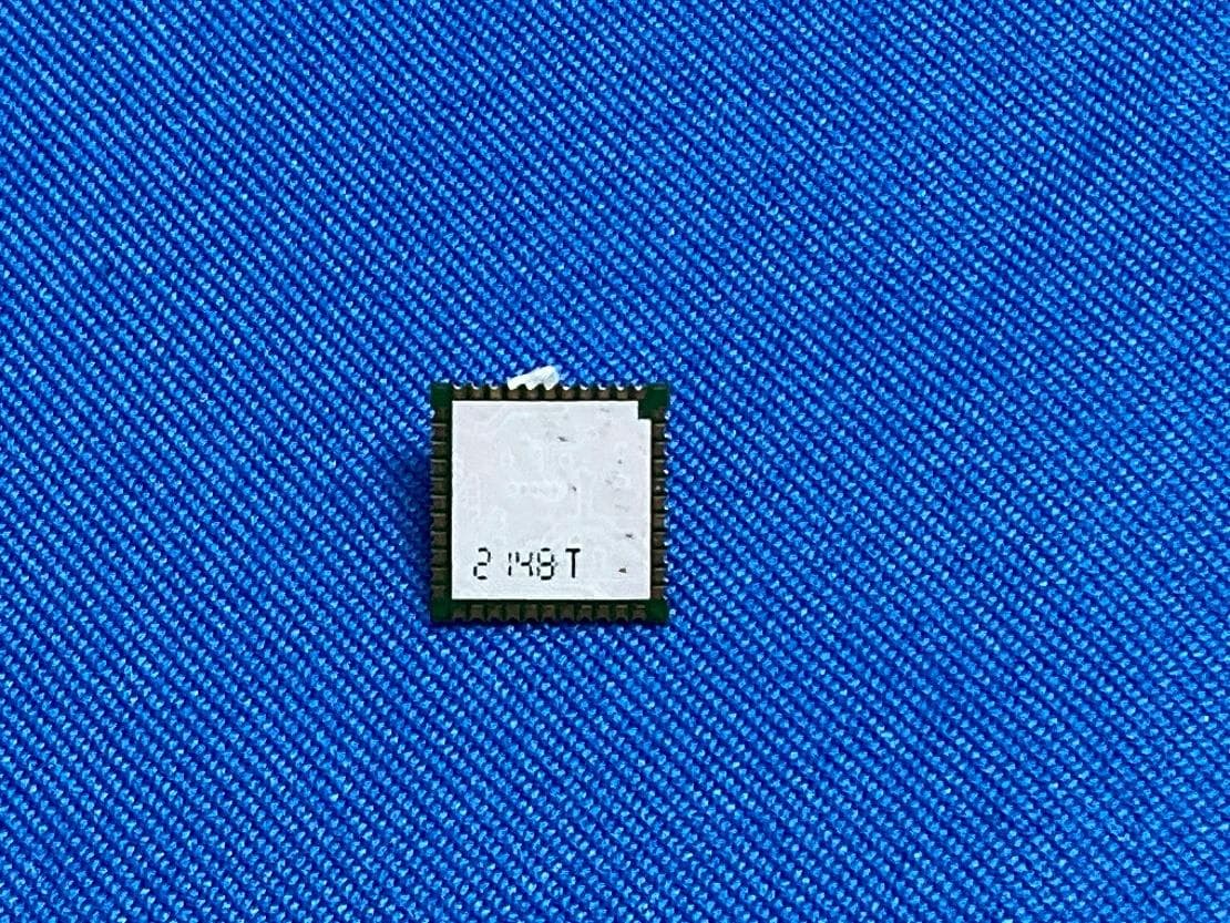
S4LFF51
Apr 09, 2023WiFi/BT Module
Equipment Class
DTS - Digital Transmission System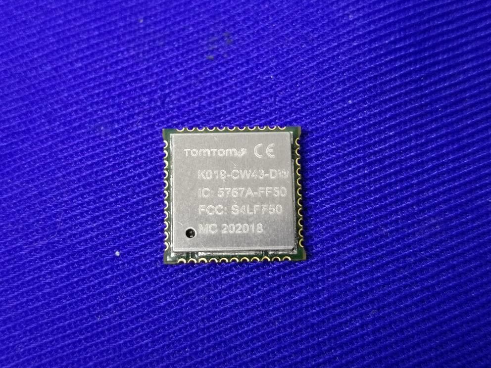
S4LFF50
Jul 01, 2020WIFI/BT Module
Equipment Class
NII - Unlicensed National Information Infrastructure TX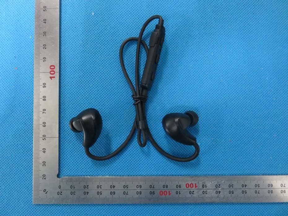
S4L4ROM
Nov 16, 2015Bluetooth Sports Headphones
Equipment Class
DSS - Part 15 Spread Spectrum Transmitter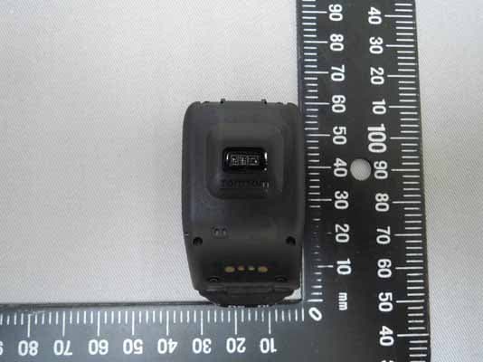
S4L4RFM
Sep 16, 2015TomTom Cardio GPS Watch
Equipment Class
DSS - Part 15 Spread Spectrum Transmitter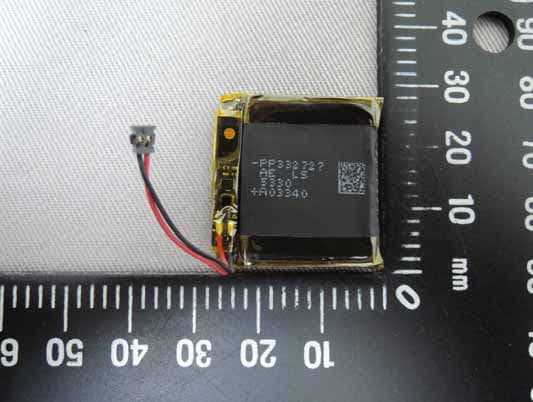
S4L4REM
Sep 16, 2015TomTom GPS Watch
Equipment Class
DTS - Digital Transmission System