S4LRIDERGPS TRACKING SYSTEM
TomTom International BV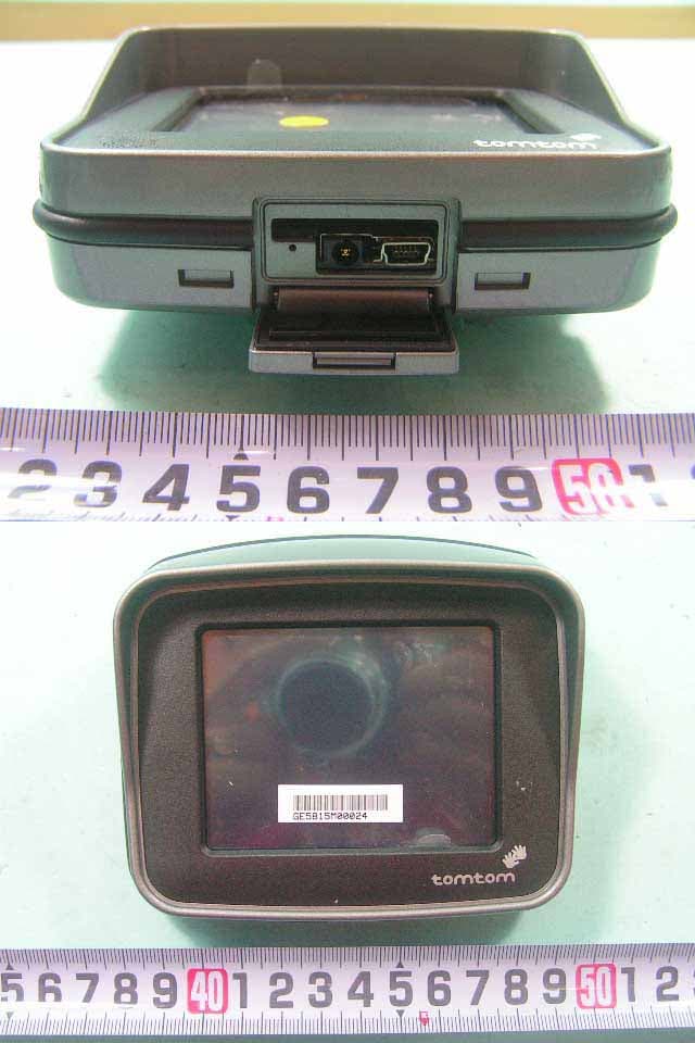
Click to zoom
Application Details
- Equipment Class
- DSS - Part 15 Spread Spectrum Transmitter
- Date of Grant
- Aug 30, 2005
- Application Purpose
- Original Equipment
- Date of Application
- Aug 30, 2005
- Equipment Note
- GPS TRACKING SYSTEM
- Frequency Range
- 2402.00000000 - 2480.00000000
- Company
- TomTom International BV
- Country
- Netherlands
Documents & Files
Document Text
Text extracted from the exhibit documents filed with the FCC. Open a document above to read the original.
Users Manual
Contents Contents ..................................................................................................................... 1 What is in the box? ..................................................................................................... 2 TomTom RIDER ......................................................................................................... 3 Using your TomTom RIDER ....................................................................................... 4 Setting up................................................................................................................ 4 Locating your current position ................................................................................. 4 Bluetooth headset module ...................................................................................... 4 Taking care of your TomTom RIDER ...................................................................... 5 Mounting the TomTom RIDER on your motorcycle .................................................... 6 Where should I mount my TomTom RIDER?.......................................................... 6 Mounting your TomTom RIDER .............................................................................. 6 Handlebar Mount .................................................................................................... 6 Handlebar adaptor .................................................................................................. 7 Mirror Mount............................................................................................................ 7 Adhesive Mount ...................................................................................................... 8 Placing your TomTom RIDER in the Holder............................................................ 8 Battery cable ........................................................................................................... 9 Making your first journey .......................................................................................... 10 Finding alternative routes...................................................................................... 10 Driving View.............................................................................................................. 12 Menus....................................................................................................................... 13 Main menu ............................................................................................................13 Driving menu......................................................................................................... 13 Why can't I open the main menu while I am driving? ............................................ 14 How can I cancel the driving menu? ..................................................................... 14 What is GPS? ........................................................................................................... 15 TomTom PLUS......................................................................................................... 16 What is in the box? [boxrider.jpg] [boxSD.jpg] [AllMountsPlusHolder.jpg] [boxScrews.jpg] [BoxPlugBike.jpg] [chargeKit.jpg] [bag.jpg] [boxUSB2.jpg] [boxCD.jpg] [BTExplainleft.jpg] [BoxHelmHeadset.jpg] [boxCarHeadset.jpg] [cleaner.jpg] [booklet.jpg] [LicenseCard.jpg] 1. Your TomTom RIDER 2. A memory card (SD card) containing the application and maps 3. Mounting kit: Holder, Handlebar Mount, Handlebar Adaptor, Mirror Mount, Adhesive Mount and the adhesive pad 4. Screws and Allen keys for the mounting kit 5. Battery cable 6. Home charger, with international adaptors 7. TomTom RIDER case 8. USB cable 9. CD for Microsoft Windows® or Apple Macintosh®. The CD contains the full manual as well as a tool for backing up your memory card. 10. Bluetooth™ headset module and headset cable 11. Helmet headset 12. Standard headset 13. Screen cloth 14. Documentation pack 15. Your product code card TomTom RIDER [NumbersRider1.jpg] [NumbersRider3.jpg] [NumberRider2a.jpg] 1. Touchscreen 2. On/Off button 3. Docking connector 4. Memory card (SD card) slot 5. USB connector 6. Charging connector 7. Reset button Using your TomTom RIDER [FromPoster5.jpg] 1. Open the compartment on the bottom of your TomTom RIDER. 2. Push the memory card into the memory card slot. 3. Press and hold the On/Off button for 2 seconds, or until your TomTom RIDER starts. The first time you switch on your TomTom RIDER, it may take up to 20 seconds to start. To switch off your TomTom RIDER, press and hold the On/Off button for 2 seconds. Setting up First, you have to answer a few questions to set up your device and your Bluetooth headset module. Answer the questions by tapping the screen. You will use the touchscreen for everything you do with your TomTom RIDER. Follow the instructions to establish a Bluetooth connection between your TomTom RIDER and your Bluetooth headset module. See the Bluetooth headset module section below for more information about your Bluetooth headset module. Once you have answered the questions, your TomTom RIDER will display the Driving View. The screen is shown in black and white until your TomTom RIDER locates your current position. Once this is done, the Driving View is shown in full colour. Locating your current position Your TomTom RIDER must be outside to be able to locate your current position. The first time you start your TomTom RIDER, it takes up to 5 minutes for the device to find your current position. In future, your position will be found much faster, normally within a few seconds. If your TomTom RIDER takes longer than 5 minutes to locate your current position, make sure that you are in an open place without tall buildings or trees around you. Your TomTom RIDER does not transmit your location, so others cannot use it to track you while you are driving. Note: Before driving with your TomTom RIDER, we recommend…
Text truncated - open the document above for the full version.
External Photos
SPORTON International Inc. PAGE NUMBER : A1 OF A17 TEL : 886-2-2696-2468 ISSUED DATE : Aug. 27, 2005 FAX : 886-2-2696-2255 APPENDIX A. Photographs of EUT SPORTON International Inc. PAGE NUMBER : A2 OF A17 TEL : 886-2-2696-2468 ISSUED DATE : Aug. 27, 2005 FAX : 886-2-2696-2255 SPORTON International Inc. PAGE NUMBER : A3 OF A17 TEL : 886-2-2696-2468 ISSUED DATE : Aug. 27, 2005 FAX : 886-2-2696-2255 SPORTON International Inc. PAGE NUMBER : A4 OF A17 TEL : 886-2-2696-2468 ISSUED DATE : Aug. 27, 2005 FAX : 886-2-2696-2255 SPORTON International Inc. PAGE NUMBER : A5 OF A17 TEL : 886-2-2696-2468 ISSUED DATE : Aug. 27, 2005 FAX : 886-2-2696-2255 SPORTON International Inc. PAGE NUMBER : A6 OF A17 TEL : 886-2-2696-2468 ISSUED DATE : Aug. 27, 2005 FAX : 886-2-2696-2255 SPORTON International Inc. PAGE NUMBER : A7 OF A17 TEL : 886-2-2696-2468 ISSUED DATE : Aug. 27, 2005 FAX : 886-2-2696-2255 SPORTON International Inc. PAGE NUMBER : A8 OF A17 TEL : 886-2-2696-2468 ISSUED DATE : Aug. 27, 2005 FAX : 886-2-2696-2255
ID Label/Location Info
Label Location
Internal Photos
SPORTON International Inc. PAGE NUMBER : A9 OF A17 TEL : 886-2-2696-2468 ISSUED DATE : Aug. 27, 2005 FAX : 886-2-2696-2255 SPORTON International Inc. PAGE NUMBER : A10 OF A17 TEL : 886-2-2696-2468 ISSUED DATE : Aug. 27, 2005 FAX : 886-2-2696-2255 SPORTON International Inc. PAGE NUMBER : A11 OF A17 TEL : 886-2-2696-2468 ISSUED DATE : Aug. 27, 2005 FAX : 886-2-2696-2255 SPORTON International Inc. PAGE NUMBER : A12 OF A17 TEL : 886-2-2696-2468 ISSUED DATE : Aug. 27, 2005 FAX : 886-2-2696-2255 SPORTON International Inc. PAGE NUMBER : A13 OF A17 TEL : 886-2-2696-2468 ISSUED DATE : Aug. 27, 2005 FAX : 886-2-2696-2255 SPORTON International Inc. PAGE NUMBER : A14 OF A17 TEL : 886-2-2696-2468 ISSUED DATE : Aug. 27, 2005 FAX : 886-2-2696-2255 SPORTON International Inc. PAGE NUMBER : A15 OF A17 TEL : 886-2-2696-2468 ISSUED DATE : Aug. 27, 2005 FAX : 886-2-2696-2255 SPORTON International Inc. PAGE NUMBER : A16 OF A17 TEL : 886-2-2696-2468 ISSUED DATE : Aug. 27, 2005 FAX : 886-2-2696-2255 SPORTON International Inc. PAGE NUMBER : A17 OF A17 TEL : 886-2-2696-2468 ISSUED DATE : Aug. 27, 2005 FAX : 886-2-2696-2255
RF Exposure Info
FCC ID: S4LRIDER Issued on Aug. 27, 2005 Report No.: FR580321 SPORTON International Inc. Page No. : 48 of 53 TEL : 886-2-2696-2468 Issued Date : Aug. 27, 2005 FAX : 886-2-2696-2255 5.10. RF Exposure 5.10.1. Limit For Maximum Permissible Exposure (MPE) This product can be classified as mobile device, so the 20cm separation distance warning is required. In this section, the power density at 20cm location is calculated to examine if it is lower than the limit. (A) Limits for Occupational / Controlled Exposure Frequency Range (MHz) Electric Field Strength (E) (V/m) Magnetic Field Strength (H) (A/m) Power Density (S) (mW/ cm²) Averaging Time |E|²,|H|² or S (minutes) 0.3-3.0 614 1.63 (100)* 6 3.0-30 1842 / f 4.89 / f (900 / f)* 6 30-300 61.4 0.163 1.0 6 300-1500 F/300 6 1500-100,000 5 6 (B) Limits for General Population / Uncontrolled Exposure Frequency Range (MHz) Electric Field Strength (E) (V/m) Magnetic Field Strength (H) (A/m) Power Density (S) (mW/cm²) Averaging Time |E|²,|H|² or S ( minutes ) 0.3-1.34 614 1.63 (100)* 30 1.34-30 824/f 2.19/f (180/f)* 30 30-300 27.5 0.073 0.2 30 300-1500 F/1500 30 1500-100,000 1.0 30 F = frequency in MHz *Plane-wave equivalent power density 5.10.2. MPE Calculation Method E (V/m) = d GP××30 Power Density: Pd (mW/cm²) = 377 2 E E = Electric field (V/m) P = Peak RF output power (mW) G = EUT Antenna numeric gain (numeric) d = Separation distance between radiator and human body (m) The formula can be changed to Pd = 2 377 30 d GP × ×× From the peak EUT RF output power, the minimum mobile separation distance, d=20cm, as well as the gain of the used antenna, the RF power density can be obtained. FCC ID: S4LRIDER Issued on Aug. 27, 2005 Report No.: FR580321 SPORTON International Inc. Page No. : 49 of 53 TEL : 886-2-2696-2468 Issued Date : Aug. 27, 2005 FAX : 886-2-2696-2255 5.10.3. Calculated Result and Limit Modulation Type: GFSK Temperature: 26°C Relative Humidity: 64% Duty Cycle of the Equipment During the Test: 45.16% Test Engineer: Vic Antenna Gain (dBi) Antenna Gain (numeric) Peak Output Power (dBm) Peak Output Power ( mW ) Power Density (S) (mW/cm²) Limit of Power Density (S) (mW/cm²) -3 0.5012 1.6300 1.4555 0.000145 1
Test Report
FCC ID: S4LRIDER Issued on Aug. 27, 2005 Report No.: FR580321 SPORTON International Inc. TEL : 886-2-2696-2468 FAX : 886-2-2696-2255 FCC TEST REPORT CATEGORY : Mobile PRODUCT NAME : GPS Tracking System FCC ID. : S4LRIDER FILING TYPE : Certification BRAND NAME : TomTom MODEL NAME : TomTom RIDER APPLICANT : TomTom BV. Rembrandtplein 35, 1017 CT Amsterdam, The Netherlands MANUFACTURER : Inventec Appliances Corp. 37, Wugong 5th, Rd., Wugu Shiang, Taipei, Taiwan 248 ISSUED BY : SPORTON INTERNATIONAL INC. 6F, No. 106, Sec. 1, Hsin Tai Wu Rd., Hsi Chih, Taipei Hsien, Taiwan, R.O.C. Statements: The test result in this report refers exclusively to the presented test model / sample. Without written approval of SPORTON International Inc., the test report shall not be reproduced except in full. Certificate or Test Report could not be used by the applicant to claim the product endorsement by NVLAP and any agency of U.S. government. The test equipment used to perform the test is calibrated and traceable to NML/ROC or NIST/USA. Lab Code: 200079-0 FCC ID: S4LRIDER Issued on Aug. 27, 2005 Report No.: FR580321 SPORTON International Inc. Page No. : i TEL : 886-2-2696-2468 Issued Date : Aug. 27, 2005 FAX : 886-2-2696-2255: Table of Contents HISTORY OF THIS TEST REPORT..............................................................................................II CERTIFICATE OF COMPLIANCE.......................................................................................................................III 1. GENERAL DESCRIPTION OF EQUIPMENT UNDER TEST...........................................................................1 1.1. Applicant ......................................................................................................................................................................................... 1 1.2. Manufacturer ................................................................................................................................................................................... 1 1.3. Basic Description of Equipment under Test.................................................................................................................................... 1 1.4. Features of Equipment under Test ................................................................................................................................................. 1 1.5. Table for Carrier Frequencies ......................................................................................................................................................... 2 2. TEST CONFIGURATION OF THE EQUIPMENT UNDER TEST .....................................................................3 2.1. Connection Diagram of Test System .............................................................................................................................................. 3 2.2. The Test Mode Description............................................................................................................................................................. 4 2.3. Description of Test Supporting Units .............................................................................................................................................. 4 3. GENERAL INFORMATION OF TEST ..............................................................................................................5 3.1. Test Facility ..................................................................................................................................................................................... 5 3.2. Standards for Methods of Measurement......................................................................................................................................... 5 3.3. Frequency Range Investigated ....................................................................................................................................................... 5 3.4. Test Distance .................................................................................................................................................................................. 5 3.5. Test Software .................................................................................................................................................................................. 5 4. LIST OF MEASUREMENTS .............................................................................................................................6 4.1. Summary of the Test Results.......................................................................................................................................................... 6 5. TEST RESULT ..................................................................................................................................................7 5.1. Test of Hopping Channel Bandwidth .............................................................................................................................................. 7 5.2. Test of Hopping Channel Separation............................................................................................................................................ 11 5.3. Test of Number of Hopping Frequency......................................................................................................................................... 15 5.4. Test of Dwell Time of Each Frequency ......................................................................................................................................... 17 5.5. Maximum Peak Output Power ...................................................................................................................................................... 24 5.6. Test of Band Edges Emission....................................................................................................................................................... 25 …
Text truncated - open the document above for the full version.
Test Setup Photos
FCC ID: S4LRIDER Issued on Aug. 27, 2005 Report No.: FR580321 SPORTON International Inc. Page No. : 33 of 53 TEL : 886-2-2696-2468 Issued Date : Aug. 27, 2005 FAX : 886-2-2696-2255 5.7.8. Photographs of Conducted Emission Test Configuration FRONT VIEW REAR VIEW FCC ID: S4LRIDER Issued on Aug. 27, 2005 Report No.: FR580321 SPORTON International Inc. Page No. : 46 of 53 TEL : 886-2-2696-2468 Issued Date : Aug. 27, 2005 FAX : 886-2-2696-2255 5.8.11. Photographs of Radiated Emission Test Configuration FRONT VIEW REAR VIEW
Contact Information
Applicant
Barto Wijlens(Head of Global Supply chain)
Test Firm
SPORTON International IncKathy Lin
Technical Specifications
| # | Rule Parts | Frequency Range | Power Output |
|---|---|---|---|
| 1 | 15C | 2.40 GHz - 2.48 GHz | 1.50 mW |
Other Applications from TomTom International BV
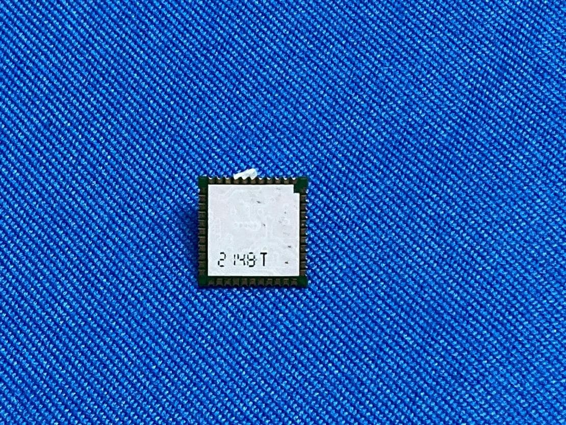
S4LFF51
Apr 09, 2023WiFi/BT Module
Equipment Class
DTS - Digital Transmission System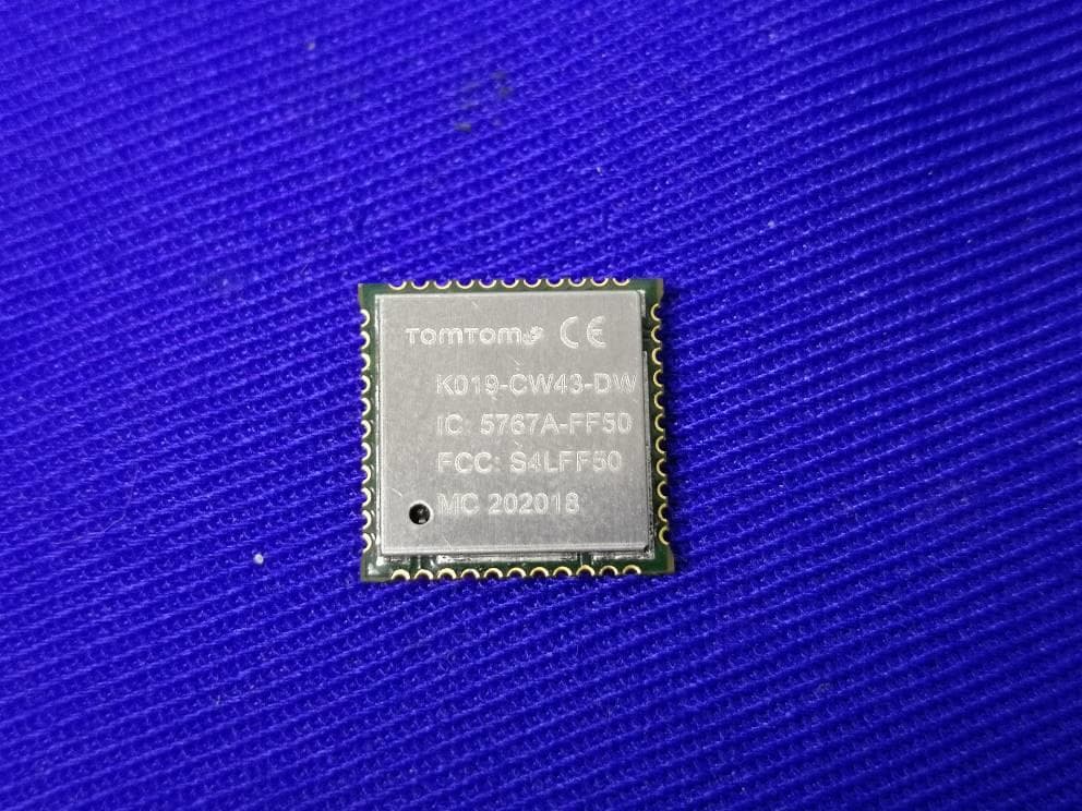
S4LFF50
Jul 01, 2020WIFI/BT Module
Equipment Class
NII - Unlicensed National Information Infrastructure TX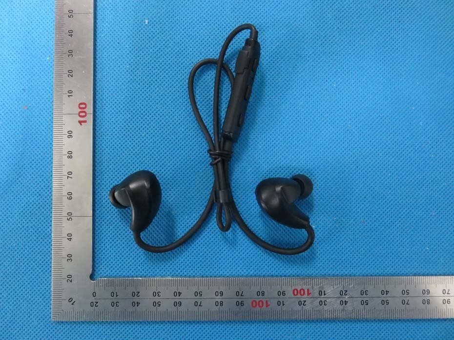
S4L4ROM
Nov 16, 2015Bluetooth Sports Headphones
Equipment Class
DSS - Part 15 Spread Spectrum Transmitter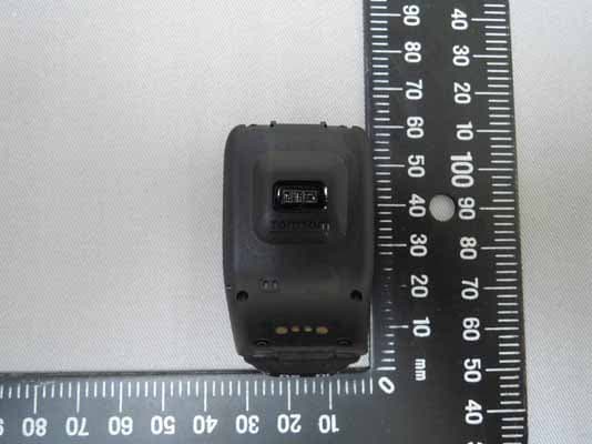
S4L4RFM
Sep 16, 2015TomTom Cardio GPS Watch
Equipment Class
DSS - Part 15 Spread Spectrum Transmitter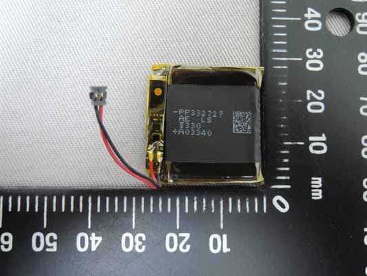
S4L4REM
Sep 16, 2015TomTom GPS Watch
Equipment Class
DTS - Digital Transmission System