S4LRIDER2NDGPS Tracking System
TomTom International BV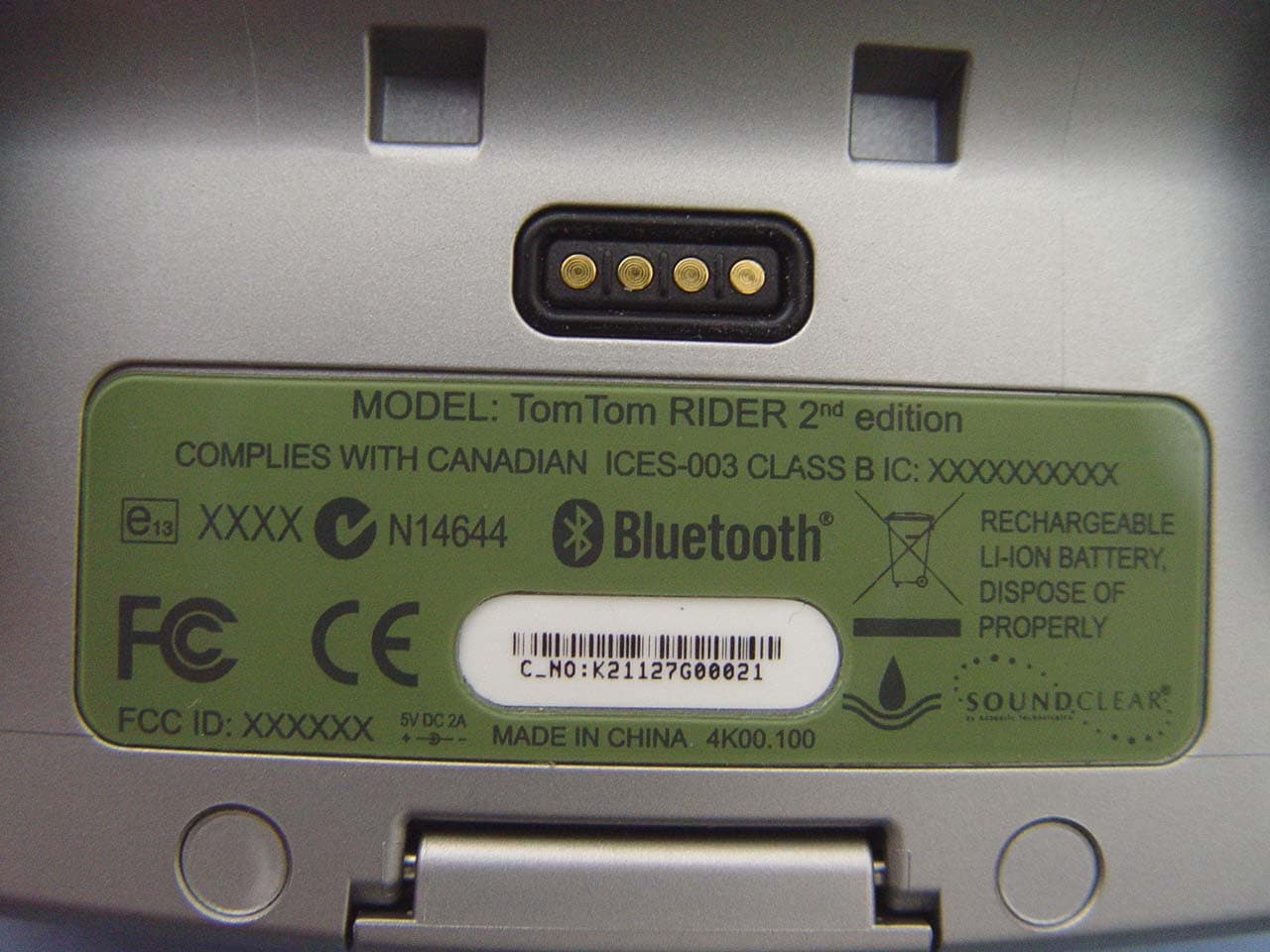
Click to zoom
Application Details
- Equipment Class
- DSS - Part 15 Spread Spectrum Transmitter
- Date of Grant
- Apr 22, 2007
- Application Purpose
- Original Equipment
- Date of Application
- Apr 22, 2007
- Equipment Note
- GPS Tracking System
- Frequency Range
- 2402.00000000 - 2480.00000000
- Company
- TomTom International BV
- Country
- Netherlands
Documents & Files
Document Text
Text extracted from the exhibit documents filed with the FCC. Open a document above to read the original.
Users Manual
1234 123 4 CMY CMMYCY CMY K Lisbon_install_part1.pdf 01/03/2007 08:21:47 1a 1b 45 2367 Click! CMY CMMYCY CMY K Lisbon_install_part2.pdf 01/03/2007 08:22:12 Tom- Tom RIDER toc_US.fm Page 1 Thursday, March 1, 2007 9:16 AM TomTom RIDER English8 Español20 Français32 Limited warranty for purchases made outside of the USA and Canada 44 EN ES FR toc_US.fm Page 2 Thursday, March 1, 2007 9:16 AM What’s in the box 8 EN What’s in the box AYour TomTom RIDER aTouchscreen bOn/Off button cMemory card (SD card) slot dUSB connector eCharging connector fReset button BYour product code cardCA memory card (SD card) 1 2 3 4 5 6 Lisbon.book Page 8 Thursday, March 1, 2007 8:39 AM What’s in the box 9 EN DCardo scala-rider™ headsetERAM Mount™ mounting kit FHolder and security strapGTomTom RIDER case HHome chargerIDocumentation pack JBattery cableKUSB cable Lisbon.book Page 9 Thursday, March 1, 2007 8:39 AM EN Using your TomTom RIDER 10 Using your TomTom RIDER Switching on 1. Open the compartment on the bottom of your TomTom RIDER. 2. Push the memory card into the memory card slot. 3. Press and hold the On/Off button for 2 seconds, or until your TomTom RIDER starts. The first time you switch on your TomTom RIDER, it may take up to 20 seconds to start. To switch off your TomTom RIDER, press and hold the On/Off button for 2 seconds. Setting up First, you have to answer a few questions to set up your device and your Cardo scala- rider™ headset. Answer the questions by tapping the screen. You will use the touchscreen for everything you do with your TomTom RIDER. Follow the instructions to establish a Bluetooth connection between your TomTom RIDER and your Cardo scala-rider™ headset. Once you have answered the questions, your TomTom RIDER will display the Driving View. The screen is shown in black and white until your TomTom RIDER locates your current position. Once this is done, the Driving View is shown in full color. Lisbon.book Page 10 Thursday, March 1, 2007 8:39 AM EN Using your TomTom RIDER 11 Cardo scala-rider™ headset AMicrophone BOn/Off button CSpeaker DLED EVolume down FVolume up GCharging connector Before you can use your Bluetooth headset, fully charge the headset using the charger supplied with the headset. Note: Make sure you use the correct charger. There are different chargers for your TomTom RIDER and your headset. Using the wrong charger may damage the device. Fully charging the headset takes between 2 and 3 hours. When charging, the LED is a steady red. When charging is finished, the LED turns off. When the batteries are running low, an alert tone is played. Using your headset To turn the headset on, press and hold the on/ off button for 6 seconds, until the LED flashes blue 3 times. An ascending alert tone is played. When the headset is on, the LED flashes blue every 3 seconds. To turn the headset off, press and hold the on/ off button for 3 seconds, until the LED flashes red 3 times. A descending alert tone is played. If you did not establish a Bluetooth connection between your Bluetooth headset module and your TomTom RIDER when you first turned your RIDER on, you can establish the connection at any time. From the Main Menu, tap Change Preferences. Tap Connect to headset and follow the instructions to establish the connection. A B C E D F G Lisbon.book Page 11 Thursday, March 1, 2007 8:39 AM EN Using your TomTom RIDER 12 Attach your headset to your helmet as shown in the Installation Poster. Make sure you position the microphone correctly. For best results, don’t position the microphone directly in front of your mouth, position it just to the side of your mouth. Locating your current position Your TomTom RIDER must be outside to be able to locate your current position. The first time you start your RIDER, it takes up to 5 minutes for the device to find your current position. In future, your position will be found much faster, normally within a few seconds. If your RIDER takes longer than 5 minutes to locate your current position, make sure that you are in an open place without tall buildings or trees around you. Your RIDER does not transmit your location, so others cannot use it to track you while you are driving. Note: Before driving with your TomTom RIDER, we recommend that you charge it fully using the home charger. Mounting your TomTom RIDER Attach the RAM™ mount kit to your motorcycle as shown on the Installation Poster, then place your RIDER in the holder. When you are attaching the mount kit to your motorcycle, follow these guidelines: • If you are unsure about attaching the mount kit yourself, ask a professional to fit it for you. • Make sure that the mount kit does not interfere with any of the controls on the motorcycle. • Always use the correct tools. If you use unsuitable tools, you may damage or break the mount kit. • Do not overtighten nuts. You may crack parts of the mount kit or damage your handlebars if you overtighten the nuts. • If you are using the u-bolt, don’t forget to put the rubber caps provided over the exposed threads. Damage due to modifications, improper installation, road hazards or accidents, are not covered. Neither RAM nor TomTom shall be liable for any injury, loss, or damage, direct or consequential, arising out of improper installation, or inability to use product. Before use, the user must determine the suitability of the product for its intended use. The user assumes all risk and liability, whatsoever, in connection with the mount. Lisbon.book Page 12 Thursday, March 1, 2007 8:39 AM EN Using your TomTom RIDER 13 Take care of your TomTom RIDER It is important to take care of your RIDER and to clean it correctly. • Use a soft cloth to wipe the screen of your RIDER; do not use any liquid cleaners. • If your RIDER gets wet, dry it with a soft cloth. • Do not open the casing of your RIDER under any circumstances. Doing so may be dangerous and will invalidate your warranty. • Do not use the memory card (SD card) with any device other than a TomTom device. Other dev…
Text truncated - open the document above for the full version.
External Photos
Compliance Certification Services Inc. Report No.: 70328002 Date of Issue: April 17, 2007 Page 1 Total Page: 15 Rev. 00 EXTERNAL PHOTOGRAPHS OF EUT Compliance Certification Services Inc. Report No.: 70328002 Date of Issue: April 17, 2007 Page 2 Rev.00 Compliance Certification Services Inc. Report No.: 70328002 Date of Issue: April 17, 2007 Page 3 Rev.00 Compliance Certification Services Inc. Report No.: 70328002 Date of Issue: April 17, 2007 Page 4 Rev.00
ID Label/Location Info
FCC ID:S4LRIDER2ND COMPLIES WITH CANADIAN ICES-003 CLASS B IC:5767A-RIDER2ND
Internal Photos
Compliance Certification Services Inc. Report No.: 70328002 Date of Issue: April 17, 2007 Page 5 Rev.00 INTERNAL PHOTOGRAPHS OF EUT Compliance Certification Services Inc. Report No.: 70328002 Date of Issue: April 17, 2007 Page 6 Rev.00 Compliance Certification Services Inc. Report No.: 70328002 Date of Issue: April 17, 2007 Page 7 Rev.00 Compliance Certification Services Inc. Report No.: 70328002 Date of Issue: April 17, 2007 Page 8 Rev.00 Compliance Certification Services Inc. Report No.: 70328002 Date of Issue: April 17, 2007 Page 9 Rev.00 Compliance Certification Services Inc. Report No.: 70328002 Date of Issue: April 17, 2007 Page 10 Rev.00 Compliance Certification Services Inc. Report No.: 70328002 Date of Issue: April 17, 2007 Page 11 Rev.00 Compliance Certification Services Inc. Report No.: 70328002 Date of Issue: April 17, 2007 Page 12 Rev.00 Compliance Certification Services Inc. Report No.: 70328002 Date of Issue: April 17, 2007 Page 13 Rev.00 Compliance Certification Services Inc. Report No.: 70328002 Date of Issue: April 17, 2007 Page 14 Rev.00 Compliance Certification Services Inc. Report No.: 70328002 Date of Issue: April 17, 2007 Page 15 Rev.00
Parts List/Tune Up Info
客 客 戶 戶 名 名 稱 稱 : :Inventec D D o o c c N N o o : : 0 0 0 0 0 0 4 4 2 2 1 1 0 0 0 0 4 4 0 0 0 0 7 7 R R e e v v : : A A 0 0 C C U U S S T T O O M M E E R R 承 承 認 認 書 書 A A P P P P R R O O V V A A L L S S H H E E E E T T 產 產 品 品 品 品 名 名 / / P P r r o o d d u u c c t t M M o o d d e e l l N N o o . . : : A A C C A A - - 5 5 3 3 2 2 0 0 - - A A 1 1 發 發 行 行 日 日 期 期 / / I I s s s s u u e e D D a a t t e e : : 2 2 0 0 0 0 5 5 / / 8 8 / / 3 3 承 承 認 認 日 日 期 期 / / A A p p p p r r o o v v e e d d D D a a t t e e : : A A p p p p r r o o v v e e d d b b y y c c u u s s t t o o m m e e r r : : ( ( s s i i g g n n i i n n g g o o r r s s t t a a m m p p i i n n g g h h e e r r e e ) ) 佳邦科技股份有限公司 INPAQ TECHNOLOGY Co., Ltd. ■ 新竹科學工業園區新竹市工業東四路 38號 □ 苗栗縣竹南鎮大厝里9鄰59-12號 No. 38, Industry E.4, RD Science-Based Industrial Park, Hsinchu , Taiwan 300, R.O.C. No. 59-12, 9 Lin, Ta Tsuo Li, Chu Nan Chen, Miao Li Hsien, Taiwan, R.O.C. UNLESS OTHER SPECIFIED TOLERANCES ON: X=± X.X=± X.XX= ANGLES=± HOLEDIA=± 佳邦科技股份有限公司 INPAQ TECHNOLOGY CO., LTD. SCALE: ----- UNIT:mm DRAWN BY:張明貴 CHECKED BY:許倬綱 DESIGNED BY:張明貴 APPROVED BY曾泓瑋 THIS DRAWINGS AND SPECIFICATIONS ARE THE PROPERTY OF INPAQ TECHNOLOGY CO.,LTD.AND SHALL NOT BE REPRODUCED OR USED AS THE BASIS FOR THE MANUFACTURE OR SALE OF APPARATUS OR DEVICES WITHOUT PERMISSION DOCUMENT PAGE REV. TITLE: ACA5320A1XX Specification NO. 000421004007 A0 PAGE 1 OF 6 LAN Chip Type Antenna Module 1. Explanation of part number : (1)Product series : LAN Antenna Chip (2)System code : X for antenna center frequency Exp.: A = 2.45G group (3)Size code : A C X X X X X X X X (1)(2)(3)(4)(5) X Exp.: 5320 = 5.3x2.0 mm (4)Type code : Exp.: A1=Type 1 (5)Suffix : UNLESS OTHER SPECIFIED TOLERANCES ON: X=± X.X=± X.XX= ANGLES=± HOLEDIA=± 佳邦科技股份有限公司 INPAQ TECHNOLOGY CO., LTD. SCALE: ----- UNIT:mm DRAWN BY:張明貴 CHECKED BY:許倬綱 DESIGNED BY:張明貴 APPROVED BY曾泓瑋 THIS DRAWINGS AND SPECIFICATIONS ARE THE PROPERTY OF INPAQ TECHNOLOGY CO.,LTD.AND SHALL NOT BE REPRODUCED OR USED AS THE BASIS FOR THE MANUFACTURE OR SALE OF APPARATUS OR DEVICES WITHOUT PERMISSION DOCUMENT PAGE REV. TITLE: ACA5320A1XX Specification NO. 000421004007 A0 PAGE 2 OF 6 2. Electrical Specification : ITEM SPECIFICATION Frequency Band 2400MHz~2500MHz VSWR Less than 2 Polarization Linear Peak Gain 0~1dBi typ. Impedance 50Ωtyp. Matching circuit : A Pi matching circuit will be required to have better performance 3. Physical Dimension : Model Size(mm) L W T D ACA5320A1XX 5.3±0.2 2.0±0.2 1.2±0.2 0.4±0.2 unit : mm UNLESS OTHER SPECIFIED TOLERANCES ON: X=± X.X=± X.XX= ANGLES=± HOLEDIA=± 佳邦科技股份有限公司 INPAQ TECHNOLOGY CO., LTD. SCALE: ----- UNIT:mm DRAWN BY:張明貴 CHECKED BY:許倬綱 DESIGNED BY:張明貴 APPROVED BY曾泓瑋 THIS DRAWINGS AND SPECIFICATIONS ARE THE PROPERTY OF INPAQ TECHNOLOGY CO.,LTD.AND SHALL NOT BE REPRODUCED OR USED AS THE BASIS FOR THE MANUFACTURE OR SALE OF APPARATUS OR DEVICES WITHOUT PERMISSION DOCUMENT PAGE REV. TITLE: ACA5320A1XX Specification NO. 000421004007 A0 PAGE 3 OF 6 4. Performance Specifications: RELIABILITY TEST Item Condition Specification Thermal shock -40°C~+85°C for 100 cycles each cycle being 30 min No apparent damage Fulfill the electrical spec. after test Humidity resistance 85±2°C, 80~90% R.H. for 500 hours No apparent damage Fulfill the electrical spec. after test High temperature resistance +85±2°C for 500 hours No apparent damage Fulfill the electrical spec. after test Low temperature resistance -40±3°C for 500 hours No apparent damage Fulfill the electrical spec. after test Vibration 10 Hz/min~55 Hz/min~10 Hz/min vibration frequency with 1.5 mm amplitude for two hours in x, y, z directions No apparent damage Drop shock Dropped onto printed circuit board from 100cm height three times in x, y, z directions. The terminals shall be protected. No apparent damage Soldering heat resistance Preheating temperature : 150±10°C Preheating time : 1 to 2 minutes Solder bath temperature : 260±5°C Bathing time : 5±0.5 seconds No apparent damage Bending test onto printed circuit board Solder specimen LTCC components on the test printed circuit board (L: 100 x W: 40 x T: 1.6mm) in appended recommended PCB pattern. Apply the load in direction of the arrow until bending reaches 2 mm. Unit: mm No apparent damage Solderability The dipped surface of the terminal shall be at least 75% covered with solder after dipped in solder bath of 235±5°C for 3±0.5 seconds. No apparent damage UNLESS OTHER SPECIFIED TOLERANCES ON: X=± X.X=± X.XX= ANGLES=± HOLEDIA=± 佳邦科技股份有限公司 INPAQ TECHNOLOGY CO., LTD. SCALE: ----- UNIT:mm DRAWN BY:張明貴 CHECKED BY:許倬綱 DESIGNED BY:張明貴 APPROVED BY曾泓瑋 THIS DRAWINGS AND SPECIFICATIONS ARE THE PROPERTY OF INPAQ TECHNOLOGY CO.,LTD.AND SHALL NOT BE REPRODUCED OR USED AS THE BASIS FOR THE MANUFACTURE OR SALE OF APPARATUS OR DEVICES WITHOUT PERMISSION DOCUMENT PAGE REV. TITLE: ACA5320A1XX Specification NO. 000421004007 A0 PAGE 4 OF 6 5. Layout Recommendation: PAD Definition: 1: Feed Termination (50 ohm feed point) 2: Solder Termination Note: Adding a 50 ohm transmission line before the feed point will be ok UNLESS OTHER SPECIFIED TOLERANCES ON: X=± X.X=± X.XX= ANGLES=± HOLEDIA=± 佳邦科技股份有限公司 INPAQ TECHNOLOGY CO., LTD. SCALE: ----- UNIT:mm DRAWN BY:張明貴 CHECKED BY:許倬綱 DESIGNED BY:張明貴 APPROVED BY曾泓瑋 THIS DRAWINGS AND SPECIFICATIONS ARE THE PROPERTY OF INPAQ TECHNOLOGY CO.,LTD.AND SHALL NOT BE REPRODUCED OR USED AS THE BASIS FOR THE MANUFACTURE OR SALE OF APPARATUS OR DEVICES WITHOUT PERMISSION DOCUMENT PAGE REV. TITLE: ACA5320A1XX Specification NO. 000421004007 A0 PAGE 5 OF 6 6. Taping Package and Label Marking: 6-1.Carrier tape dimensions UNLESS OTHER SPECIFIED TOLERANCES ON: X=± X.X=± X.XX= ANGLES=± HOLEDIA=± 佳邦科技股份有限公司 INPAQ TECHNOLOGY CO., LTD. SCALE: ----- UNIT:mm DRAWN BY:張明貴 CHECKED BY:許倬綱 DESIGNED BY:張明貴 APPROVED BY曾泓瑋 THIS DRAWINGS AND SPECIFICATIONS ARE THE PROPERTY OF INPAQ TECHNOLOGY CO.,LTD.AND SHALL NOT BE REPRODUCED OR USED AS THE BASIS FOR THE MANUFACTURE OR SALE OF APPARATUS OR DEVICES WITHOUT PERMISSION DOCUMENT PAGE REV. TIT…
Text truncated - open the document above for the full version.
Test Report
Compliance Certification Services Inc. Report No.: 70328002-RP1 FCC ID: S4LRIDER2ND Date of Issue: April 17, 2007 Note: This report shall not be reproduced except in full, without the written approval of Compliance Certification Services Inc. This document may be altered or revised by Compliance Certification Services Inc. personnel only, and shall be noted in the revision section of the document. Page 1 Total Page: 48 Rev. 00 FCC 47 CFR PART 15 SUBPART C TEST REPORT For GPS Tracking System Model: TomTom RIDER 2 nd edition Trade Name: TomTom Issued to TomTom International BV. Rembrandtplein 35, 1017 CT Amsterdam, The Netherlands Issued by Compliance Certification Services Inc. No. 81-1, Lane 210, Bade Rd. 2, Luchu Hsiang, Taoyuan Hsien, (338) Taiwan, R.O.C. http://www.ccsemc.com.tw [email protected] Compliance Certification Services Inc. Report No.: 70328002-RP1 FCC ID: S4LRIDER2ND Date of Issue: April 17, 2007 Page 2 Rev. 00 TABLE OF CONTENTS 1. TEST RESULT CERTIFICATION.....................................................................................................3 2. EUT DESCRIPTION...........................................................................................................................4 3. TEST METHODOLOGY....................................................................................................................5 3.1 EUT CONFIGURATION.....................................................................................................................5 3.2 EUT EXERCISE.................................................................................................................................5 3.3 GENERAL TEST PROCEDURES..........................................................................................................5 3.4 FCC PART 15.205 RESTRICTED BANDS OF OPERATIONS.....................................................6 3.5 DESCRIPTION OF TEST MODES........................................................................................................7 4. INSTRUMENT CALIBRATION........................................................................................................8 4.1 MEASURING INSTRUMENT CALIBRATION...................................................................................8 4.2 MEASUREMENT EQUIPMENT USED......................................................................................8 5. FACILITIES AND ACCREDITATIONS ...........................................................................................9 5.1 FACILITIES ......................................................................................................................................9 5.2 EQUIPMENT.....................................................................................................................................9 5.3 TABLE OF ACCREDITATIONS AND LISTINGS..................................................................................10 6. SETUP OF EQUIPMENT UNDER TEST........................................................................................11 6.1 SETUP CONFIGURATION OF EUT....................................................................................................11 6.2 SUPPORT EQUIPMENT ............................................................................................................11 7. FCC PART 15.247 REQUIREMENTS.............................................................................................12 7.1 PEAK POWER.................................................................................................................................12 7.2 BAND EDGES MEASUREMENT .............................................................................................13 7.3 PEAK POWER SPECTRAL DENSITY.................................................................................................18 7.4 FREQUENCY SEPARATION....................................................................................................21 7.5 NUMBER OF HOPPING FREQUENCY ...................................................................................23 7.6 TIME OF OCCUPANCY (DWELL TIME)................................................................................25 7.7 SPURIO US EMISSIONS .............................................................................................................32 7.8 POWERLINE CONDUCTED EMISSIONS............................................................................................42 APPENDIX I RADIO FREQUENCY EXPOSURE ................................................................................45 APPENDIX II PHOTOGRAPHS OF TEST SETUP ...............................................................................46 Compliance Certification Services Inc. Report No.: 70328002-RP1 FCC ID: S4LRIDER2ND Date of Issue: April 17, 2007 Page 4 Rev. 00 2. EUT DESCRIPTION Product GPS Tracking System Trade Name TomTom Model Number TomTom RIDER 2 nd edition Model Discrepancy N/A Power Supply 1. Power Adapter: Model: A10P1-05MP I/P: AC 100-240V, 0.3A, 47-63Hz O/P: DC 5V, 2.0A 2. Battery: Type: MALAGA Battery SPEC: SAMSUNG ICR 18650-22, 2200mAh Frequency Range 2402 ~ 2480 MHz Transmit Power 2.53 dBm Modulation Technique FHSS (GFSK) Transmit Data Rate 1Mbps Number of Channels 79 Channels Antenna Specification Gain: 1 dBi Antenna Designation Chip Antenna Remark: 1. The sample selected for test was production product and was provided by manufacturer. 2. This submittal(s) (test report) is intended for FCC ID: S4LRIDER2ND filing to comply with Section 15.207, 15.209 and 15.247 of the FCC Part 15, Subpart C Rules. Compliance Certification Services Inc. Report No.: 70328002-RP1 FCC ID: S4LRIDER2ND Date of Issue: April 17, 2007 Page 5 Rev. 00 3. TEST METHODOLOGY The tests documented in this report were performed in accordance with ANSI C63.4 and FCC CFR 47 2.1046, 2.1047, 2.1049, 2.1051, 2.1053, 2.1055, 2.1057, 15.207, 15.209 and 15.247. 3.1 EUT CONFIGURATION The EUT configurati…
Text truncated - open the document above for the full version.
Test Setup Photos
Compliance Certification Services Inc. Report No.: 70328002-RP1 FCC ID: S4LRIDER2ND Date of Issue: April 17, 2007 Page 46 Rev. 00 APPENDIX II PHOTOGRAPHS OF TEST SETUP CONDUCTED EMISSION SETUP PHOTO Compliance Certification Services Inc. Report No.: 70328002-RP1 FCC ID: S4LRIDER2ND Date of Issue: April 17, 2007 Page 47 Rev. 00 RADIATED EMISSION SETUP PHOTOS Compliance Certification Services Inc. Report No.: 70328002-RP1 FCC ID: S4LRIDER2ND Date of Issue: April 17, 2007 Page 48 Rev. 00 POWERLINE CONDUCTED EMISSIONS SETUP PHOTOS
Contact Information
Applicant
Barto Wijlens(Head of Global Supply chain)
Test Firm
Compliance Certification Services Inc.Harris Lai
Technical Specifications
| # | Rule Parts | Frequency Range | Power Output |
|---|---|---|---|
| 1 | 15C | 2.40 GHz - 2.48 GHz | 1.79 mW |
Other Applications from TomTom International BV
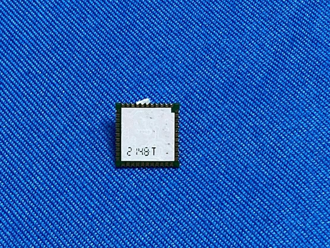
S4LFF51
Apr 09, 2023WiFi/BT Module
Equipment Class
DTS - Digital Transmission System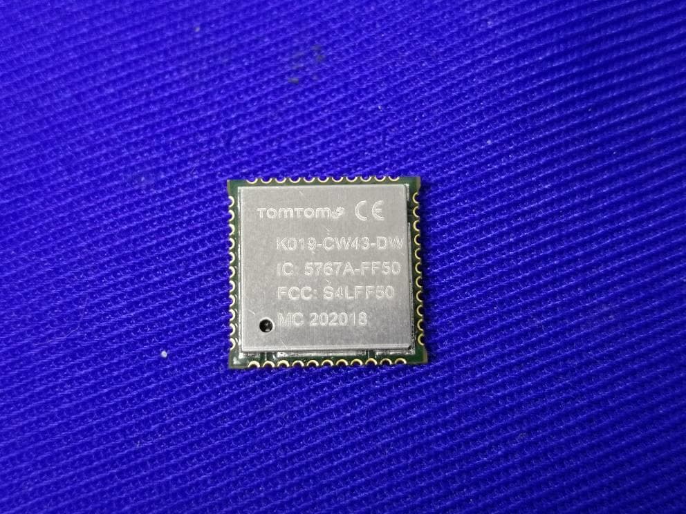
S4LFF50
Jul 01, 2020WIFI/BT Module
Equipment Class
NII - Unlicensed National Information Infrastructure TX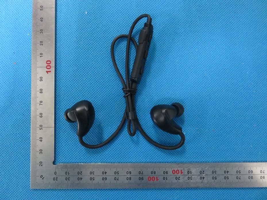
S4L4ROM
Nov 16, 2015Bluetooth Sports Headphones
Equipment Class
DSS - Part 15 Spread Spectrum Transmitter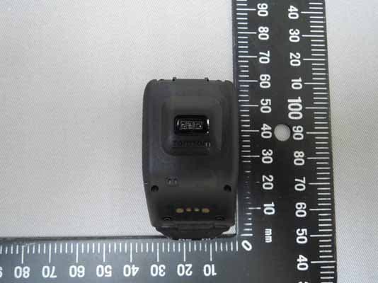
S4L4RFM
Sep 16, 2015TomTom Cardio GPS Watch
Equipment Class
DSS - Part 15 Spread Spectrum Transmitter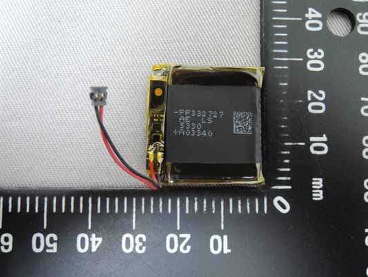
S4L4REM
Sep 16, 2015TomTom GPS Watch
Equipment Class
DTS - Digital Transmission System