S4MGC1000GATEWAY CONTROLLER
TeraHop Networks Incorporated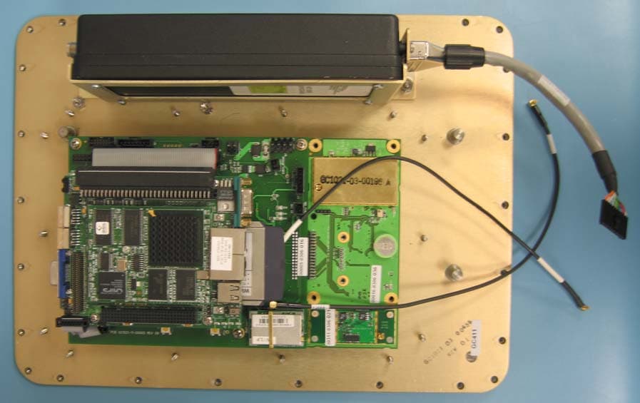
Click to zoom
Application Details
- Equipment Class
- DSS - Part 15 Spread Spectrum Transmitter
- Date of Grant
- Aug 03, 2006
- Application Purpose
- Original Equipment
- Date of Application
- Aug 03, 2006
- Equipment Note
- GATEWAY CONTROLLER
- Frequency Range
- 2406.00000000 - 2474.00000000
- Country
- United States
Documents & Files
Document Text
Text extracted from the exhibit documents filed with the FCC. Open a document above to read the original.
Users Manual
GC1000-03-00559 (REV. 01) PAGE 1 OF 7 INSTALLATION INSTRUCTIONS P OLE MOUNTED GC1030/1040 (GC1000-03-00516) This equipment complies with Part 15 of the FCC rules. And changes or modifications not expressly approved by the manufacturer could the void the user’s authority to operate the equipment. WARNING: This device must be installed in a location that is not accessible to the general public. Install the device so that the antenna is more than 20 cm from the unsuspecting personnel. Failure to install this device as described will result in a failure to comply with FCC rules for rf exposure and is discouraged. GC1000-03-00559 (REV. 01) PAGE 2 OF 7 COMPONENT LIST A – 1 pc B – 1 pc 1030/1040 Gateway (GC1000-03-00516) Pole Mount (GC1021-03-00081) C – 4 pc D – 2 pcs ¼”-20 x ¾” long screw Tube Clamp E – 1 pc F – 1 pc Flat Mount Bracket (GC1021-03-00542) Ethernet Crossover Cable (GC1021-04-00260) G – 1 pc H – 1 pc Infrared Sensor (GC1021-03-00205) 12 VDC Power Supply (GC1021-03-00368) I – 1 pc J – 1 pc IEC C13 Power Cable Battery Jumper Cable (GC1021-04-00213) GC1000-03-00559 (REV. 01) PAGE 3 OF 7 TOOLS NEEDED - Flat head screwdriver - Phillips head screwdriver STEP 1 With the Phillips head screwdriver, assemble the Pole Mount (B) to the 1030/1040 Gateway (A) using the ¼”-20 screws (C). See Figure 1 below. For mounting the Gateway to a round pole or to the corner of a square pole, proceed to Step 2. For mounting the Gateway to the flat side of a square pole, proceed to Step 3. Figure 1 STEP 2 Position the assembled Pole Mount (B) and 1030/1040 Gateway (A) against the round pole or corner of the square pole. Make sure that the bulkhead fittings of the Gateway are facing downward (see Figure 2). Wrap a Tube Clamp (D) around the pole through the clamp holes (labeled in Figure 2) in the Pole Mount GC1000-03-00559 (REV. 01) PAGE 4 OF 7 (B). Wrap another Tube Clamp (D) around the pole through the other set of clamp holes in the Pole Mount (B). Tighten the screw on the Tube Clamps (D) with the flat head screw driver to fasten the 1030/1040 Gateway (A) to the pole. See Figure 2. Figure 2 STEP 3 Attach the Flat Mount Bracket (E) to the back of the Pole Mount (B) as shown in Figure 3. Position the assembled 1030/1040 Gateway (A), Pole Mount (B), and Flat Mount Bracket (E) against the flat side of the square pole. Make sure that the bulkhead fittings of the Gateway are facing downward (see Figure 3). Wrap a Tube Clamp (D) around the pole through the clamp holes (labeled in Figure 3) in the Pole Mount (B). Wrap another Tube Clamp (D) around the pole through the other set of clamp holes in the Pole Mount (B). Tighten the screw on the Tube Clamps (D) with the flat head screw driver to fasten the 1030/1040 Gateway (A) to the pole. GC1000-03-00559 (REV. 01) PAGE 5 OF 7 Figure 3 STEP 4 If you are going to connect the Gateway to a Battery Pack, attach the female end of the Battery Jumper Cable (J) to the Battery Input bulkhead fitting (see Figure 4) of the 1030/1040 Gateway (A) as shown in Figure 5. STEP 5 If you are going to connect the Gateway to a 12 VDC Power Supply (H), attach the female end of the Power Supply cable to the DC Input bulkhead fitting (see Figure 4) of the 1030/1040 Gateway (A) as shown in Figure 5. Attach the IEC C13 Power Cable (I) to the Power Supply. GC1000-03-00559 (REV. 01) PAGE 6 OF 7 Figure 4 STEP 6 If you are going to use the Infrared Sensor (G), attach the female end of the Infrared Sensor cable to the Sensor bulkhead fitting (see Figure 4) of the 1030/1040 Gateway (A) as shown in Figure 5. S TEP 7 If you are going to use the Ethernet port on the Gateway, first unscrew the Ethernet Dust Cap from the Ethernet Bulkhead Fitting (see Figure 4). Attach the Ethernet Crossover Cable (F) to the Ethernet Bulkhead Fitting as shown in Figure 5. GC1000-03-00559 (REV. 01) PAGE 7 OF 7 Figure 5 For questions or assistance, please contact: TeraHop Networks, Inc. Alpharetta, GA 30005 (678) 455-8844 www.terahop.com
External Photos
Picture Title: ASSY, GC 1030 Document Number: GC1030-13-00516 Issue Date: 05/08/06 Page 1 of 2 Revision: 01 Revision Date: External View Internal View w/ Outer Cover Removed Picture Title: ASSY, GC 1030 Document Number: GC1030-13-00516 Page 2 of 2 Internal View w/ Electronics Cover Removed Internal Side View w/ Electronics Cover Removed
External Photos
Picture Title: ASSY, GC 1040 Document Number: GC1040-13-00516 Issue Date: 05/08/06 Page 1 of 2 Revision: 01 Revision Date: External View Internal View w/ Outer Cover Removed Picture Title: ASSY, GC 1040 Document Number: GC1040-13-00516 Page 2 of 2 Internal View w/ Electronics Cover Removed Internal Side View w/ Electronics Cover Removed
ID Label/Location Info
Model: GC1040 FCC ID: S4MGC1000 This device complies with Part 15 of the FCC rules subject to the following two conditions: (1) This device may not cause harmful interference, and (2) This device must accept all interference received, including interference that may cause undesired operation. TeraHop Networks Model: GC1030 FCC ID: S4MGC1000 This device complies with Part 15 of the FCC rules subject to the following two conditions: (1) This device may not cause harmful interference, and (2) This device must accept all interference received, including interference that may cause undesired operation. TeraHop Networks
Internal Photos
Picture Title: Bluetooth Assembly Document Number: GC1021-13-00311 Issue Date: 05/08/06 Page 1 of 1 Revision: 03 Revision Date: Assembly: GC1021-04-00311 REV 03 Raw Board: GC1021-11-00311 REV 03 Top View Bottom View
Internal Photos
Picture Title: Antenna Panel Assembly Document Number: GC1021-13-00382 Issue Date: 05/08/06 Page 1 of 2 Revision: 03 Revision Date: Assembly: GC1021-04-00382 REV 03 Raw Board: GC1021-11-00382 REV 03 Top View Picture Title: Antenna Panel Assembly Document Number: GC1021-13-00382 Page 2 of 2 Bottom View
Internal Photos
Picture Title: Adapter Board Assembly Document Number: GC1040-13-00455 Issue Date: 05/08/06 Page 1 of 1 Revision: 01 Revision Date: Assembly: GC1040-04-00455 REV 01 Raw Board: GC1040-11-00455 REV 01 Top View Bottom View
Internal Photos
Picture Title: I/O Panel Assembly Document Number: GC1021-13-00384 Issue Date: 05/08/06 Page 1 of 1 Revision: 02 Revision Date: Assembly: GC1021-04-00384 REV 02 Raw Board: GC1021-11-00384 REV 02 Top View Bottom View
Internal Photos
Picture Title: Main Board Assembly Document Number: GC1021-13-00005 Issue Date: 05/08/06 Page 1 of 2 Revision: 09 Revision Date: Assembly: GC1021-04-00005 REV 09 Raw Board: GC1021-11-00005 REV 09 Top View Picture Title: Main Board Assembly Document Number: GC1021-13-00005 Page 2 of 2 Bottom View
Internal Photos
Picture Title: TRX Board Assembly Document Number: RSI200-13-00004 Issue Date: 05/08/06 Page 1 of 1 Revision: 11a Revision Date: Assembly: RSI200-04-00004 REV 11a Raw Board: RSI200-11-00004 REV 11a Top View Bottom View
Internal Photos
Picture Title: TTX Board Assembly Document Number: GC1021-13-00016 Issue Date: 05/08/06 Page 1 of 2 Revision: 09 Revision Date: Assembly: GC1021-04-00016 REV 09 Raw Board: GC1021-11-00016 REV 09 Top View w/o TTX Shield Bottom View w/o TTX Shield Picture Title: TTX Board Assembly Document Number: GC1021-13-00005 Page 2 of 2 Top View w/ TTX Shield Bottom View w/ TTX Shield
Operational Description
TeraHop Gateway/Controller Technical Overview Thursday, May 18, 2006 Controller (GC1040) The Controller is a server/gateway, which contains a single board computer, hard drive, Ethernet, WiFi, server software and the database. The GC1040 is designed to communicate to users via WiFi and system components via Class Based Networking, and Bluetooth. The Controller contains a hard disk drive and runs the Server software. In typical deployments, a second Controller is also installed to act as a backup to provide continued operation if a failure of the primary Controller occurs (to be completed in a future release). The Controller is also able to support Ethernet, mobile phone (T-Mobile and Sprint) and satellite (Iridium) links back to the MSS for backup and maintenance. Gateway (GC1030) Gateway contains a single board computer, Ethernet, WiFi for communication to the GC1040. The GC1030 is designed to communicate to system components via WiFi, Class Based Networking, Bluetooth and RCR. Gateways supply a bridge between the Controller and the appropriate senors. In future releases, the Gateways will be configured as a WiFi bridge to “hop” gateways back to the Controller. Gateways can optionally be equipped with mobile phone (Sprint and T-Mobile) and Satellite (Iridium) data modems to link remotely to network elements. Gateways contain a GPS Receiver that is used to determine the Gateway’s exact location. Product Performance Characteristics Specification Gateway (GC1030) WiFi (802.11b) Frequency: GHz Data rate: up to 11 Mbps Range: average 100 m Mobile Phone (T-Mobile) Tri-band GSM Frequencies: 900, 1800, 1900 MHz Range: approximately 7 miles from mobile tower Mobile Phone (Sprint) Frequency: 1900 MHz Range: approximately 7 miles from mobile tower Satellite (Iridium) Frequency: 1600 MHz Data Rate: 2400 bps Bluetooth Frequency: 2.4 GHz Data Rate: up to 1 Mbps Range: average 100m TTO (Tag Turn On) Frequency: 2.4 GHz Range: average 100m GPS Frequency: 1.54 GHz Position: approximately 3 feet, assuming no multipath Temperature Range Operating -20C to +60C Storage: -40C to +70C Power AC100 to 230 VAC 50/60 Hz; DC 8-15 VDC 400 milliamps (stand conf) Size 10.75 in x 14.25 in x 4.75 in Weight 9 lbs Controller (GC1040) Hard Drive 30 GB Server Application KeyZone Operating System
RF Exposure Info
Company TeraHop Networks Inc. ModelGC1030/1040 FCC IDS4MGC1000 Report6L0185Rus1 Prediction of MPE limit at a given distance Equation from page 18 of OET Bulletin 65, Edition 97-01 where:S = power density P = power input to the antenna G = power gain of the antenna in the direction of interest relative to an isotropic radiator R = distance to the center of radiation of the antenna Maximum peak output power at antenna input terminal:27.00(dBm) Maximum peak output power at antenna input terminal:501.1872336(mW) Antenna gain(typical):5(dBi) Maximum antenna gain:3.16227766(numeric) Time Averaging:100(%) Prediction distance:20(cm) Prediction frequency:2400(MHz) MPE limit for uncontrolled exposure at prediction frequency:1(mW/cm^2) Power density at prediction frequency:0.315304(mW/cm^2) Margin of compliance:-5.0(dB) 2 4R PG S π =
Test Report
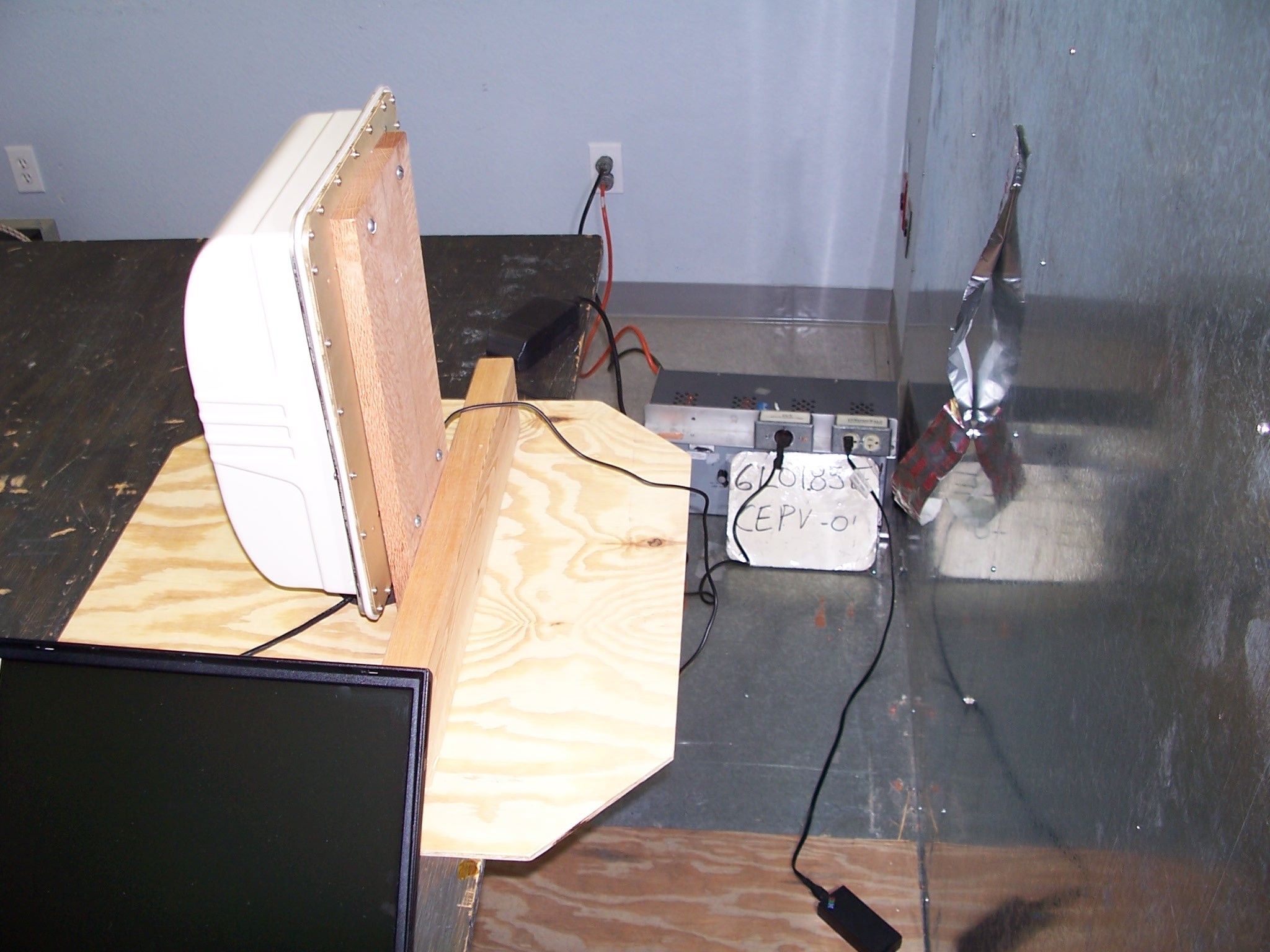
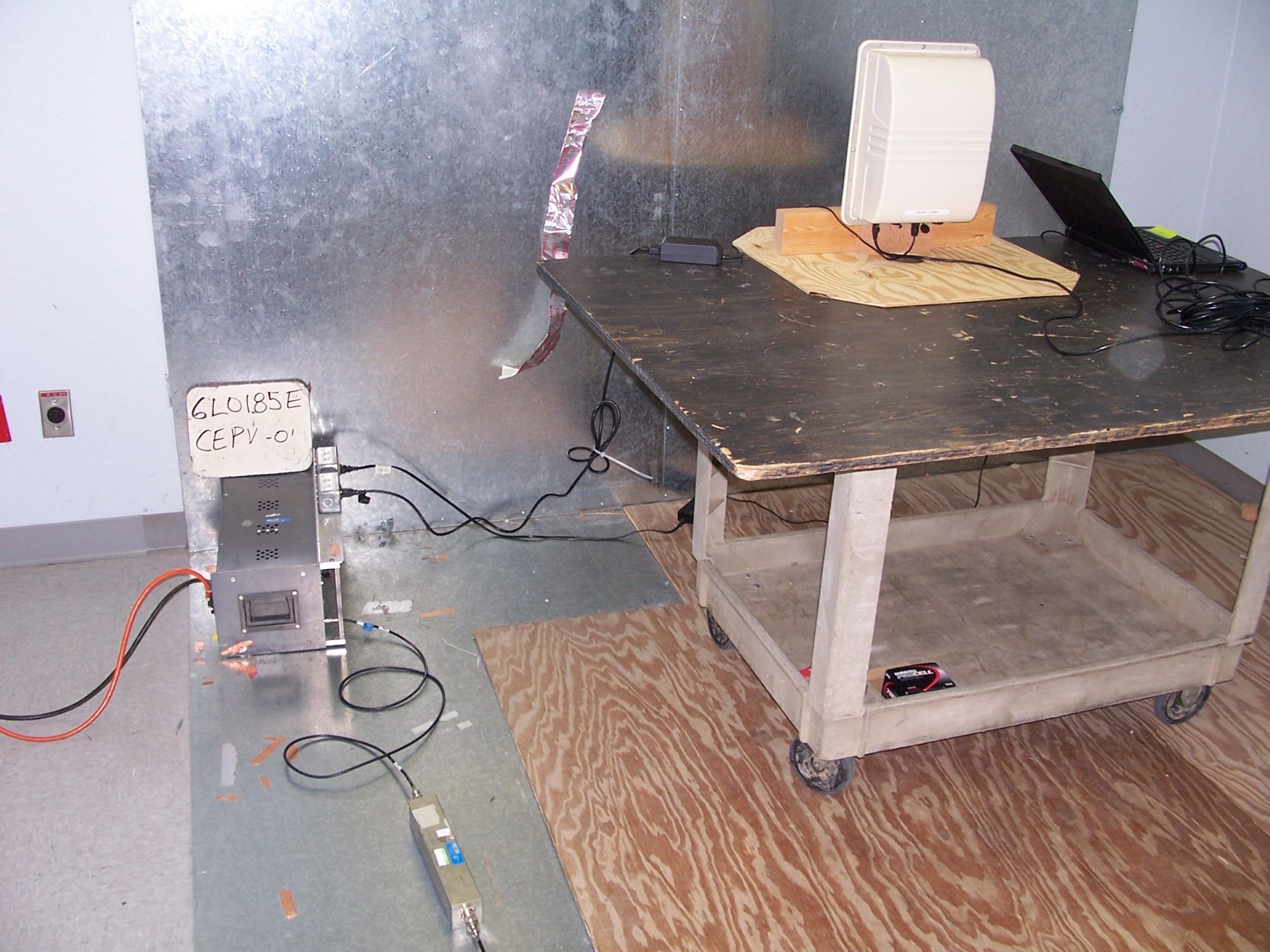
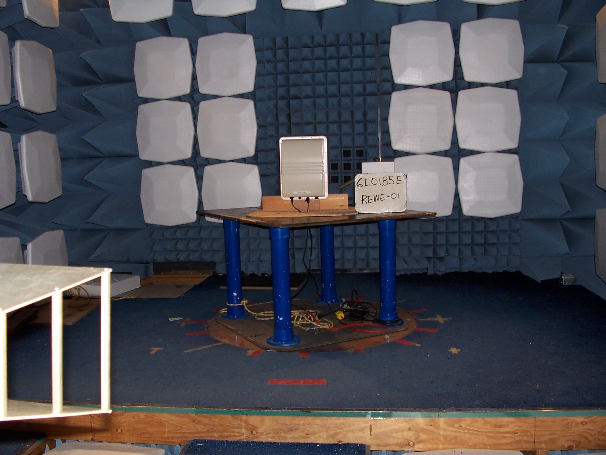
Nemko Test Report: 6L0185RUS1 Applicant: TeraHop Networks, Inc. 1225 Old Alpharetta Road Suite 210 Alpharetta, GA 30005 Equipment Under Test: Gateway Controller model GC1030/40 (E.U.T.) In Accordance With: FCC Part 15, Subpart C, 15.247 Frequency Hopping Transmitters Tested By: Nemko USA Inc. 802 N. Kealy Lewisville, Texas 75057-3136 Authorized By: Kevin Rose Wireless Engineer Date: May 19, 2006 Nemko USA, Inc. FCC PART 15, SUBPART C FREQUENCY HOPPING SPREAD SPECTRUM TRANSMITTER EQUIPMENT: Gateway Controller GC1030/40 Test Report No.: 6L0185RUS1 Page 2 of 45 Table of Contents Section 1. Summary of Test Results ................................................................... 3 Section 2. Equipment Under Test (E.U.T.) ......................................................... 5 Section 3. Powerline Conducted Emissions ........................................................ 7 Section 4. Channel Separation........................................................................... 10 Section 5. Time of Occupancy .......................................................................... 13 Section 6. Occupied Bandwidth ........................................................................ 16 Section 7. Peak Power Output ........................................................................... 20 Section 8. Spurious Emissions (Antenna Conducted)....................................... 21 Section 9. Spurious Emissions (Radiated) ........................................................ 26 Section 10. Test Equipment List ....................................................................... 32 ANNEX A - TEST DETAILS ............................................................................... 33 ANNEX B - TEST DIAGRAMS........................................................................... 43 Nemko USA, Inc. FCC PART 15, SUBPART C FREQUENCY HOPPING SPREAD SPECTRUM TRANSMITTER EQUIPMENT: Gateway Controller GC1030/40 Test Report No.: 6L0185RUS1 Page 3 of 45 Section 1. Summary of Test Results Manufacturer: TeraHop Networks, Inc. Model No.: Gateway Controller Serial No.: None General: All measurements are traceable to national standards. These tests were conducted on a sample of the equipment for the purpose of demonstrating compliance with Part 15, Subpart C, Paragraph 15.247 for Frequency Hopping Spread Spectrum devices. Radiated tests were conducted is accordance with ANSI C63.4-1992. Radiated emissions are made on an open area test site. A description of the test facility is on file with the FCC. New Submission Production Unit Class II Permissive Change Pre-Production Unit THIS TEST REPORT RELATES ONLY TO THE ITEM(S) TESTED. THE FOLLOWING DEVIATIONS FROM, ADDITIONS TO, OR EXCLUSIONS FROM THE TEST SPECIFICATIONS HAVE BEEN MADE. NONE See “ Summary of Test Data”. NVLAP LAB CODE: 100426-0 Nemko USA Inc. authorizes the above named company to reproduce this report provided it is reproduced in its entirety and for use by the company’s employees only. Any use which a third party makes of this report, or any reliance on or decisions to be made based on it, are the responsibility of such third parties. Nemko USA Inc. accepts no responsibility for damages, if any, suffered by any third party as a result of decisions made or actions based on this report. This report applies only to the items tested. Nemko USA, Inc. FCC PART 15, SUBPART C FREQUENCY HOPPING SPREAD SPECTRUM TRANSMITTER EQUIPMENT: Gateway Controller GC1030/40 Test Report No.: 6L0185RUS1 Page 4 of 45 Summary Of Test Data NAME OF TEST PARA. NO. RESULT Powerline Conducted Emissions 15.207(a) Complies Channel Separation 15.247(a)(1) Complies Time of Occupancy 15.247(a)(1)(ii) Complies 20 dB Occupied Bandwidth 15.247(a)(1) Complies Peak Power Output 15.247(b) Complies Spurious Emissions (Antenna Conducted) 15.247(c) Complies Spurious Emissions (Radiated) 15.247(c) Complies Footnotes: Nemko USA, Inc. FCC PART 15, SUBPART C FREQUENCY HOPPING SPREAD SPECTRUM TRANSMITTER EQUIPMENT: Gateway Controller GC1030/40 Test Report No.: 6L0185RUS1 Page 5 of 45 Section 2. Equipment Under Test (E.U.T.) General Equipment Information Frequency Band: 902 – 928 MHz 2400 – 2483.5 MHz Frequency Range of EUT: Bluetooth: 2402 – 2480 MHz TTX: 2406 – 2474 MHz Number of Channels: Bluetooth: 79 TTX: 76 Channel Spacing: Bluetooth: 1 MHz TTX: 800 kHz Power Output (EIRP): Bluetooth: 39.8 mW TTX: 1.58 W User Frequency Adjustment: Software controlled Nemko USA, Inc. FCC PART 15, SUBPART C FREQUENCY HOPPING SPREAD SPECTRUM TRANSMITTER EQUIPMENT: Gateway Controller GC1030/40 Test Report No.: 6L0185RUS1 Page 6 of 45 Description of EUT The GC is critical link between the sensors and the WAN. The sensors communicate with the GC over Bluetooth. The GC can communicate with a WAN via cell, WiFi, or sat modem. System Diagram Nemko USA, Inc. FCC PART 15, SUBPART C FREQUENCY HOPPING SPREAD SPECTRUM TRANSMITTER EQUIPMENT: Gateway Controller GC1030/40 Test Report No.: 6L0185RUS1 Page 7 of 45 Section 3. Powerline Conducted Emissions NAME OF TEST: Powerline Conducted Emissions PARA. NO.: 15.207(a) TESTED BY: Arturo Ruvalcaba DATE: 16 May 2006 Test Results: Complies. Measurement Data: See attached plots. Equipment Used: 969-1433-1984-970-1284 Measurement Uncertainty: +/- 10. 7 dB Temperature: 22 °C Relative Humidity: 33 % Nemko USA, Inc. FCC PART 15, SUBPART C FREQUENCY HOPPING SPREAD SPECTRUM TRANSMITTER EQUIPMENT: Gateway Controller GC1030/40 Test Report No.: 6L0185RUS1 Page 8 of 45 Test Data – Powerline Conducted Emissions Meas.EUTDetectorLimitMeterPathTransducerCorrectedSpec.limitCR/SLPass Freq. TestTypeTypeReadingLossFactorReading(dBuV)Diff.Fail (MHz)Point(P,QP, A)(QP, A)(dBuV)(dB)(dB)(dBuV)Q.P.Avg.(dB)Unc.Comment 0.16NQPQP53.01155.065.46 55.464 -10.5Pass 0.16NAA42.01144.065.46 55.464 -11.5Pass 0.202NQPQP48.01150.063.53 53.528 -13.5Pass 0.202NAA40.01142.063.53 53.528 -11.5Pass 0.242NQPQP45.01147.062.03 52.028 -15.0Pass 0.242NAA39.01141.062.03 52.028 -11.0Pass 0.401NQPQP45.01147.057.…
Text truncated - open the document above for the full version.
Contact Information
Applicant
Greg Fletcher(Chief Financial Officer)
Test Firm
Nemko USA, Inc.Tom Tidwell
Technical Specifications
| # | Rule Parts | Frequency Range | Power Output |
|---|---|---|---|
| 2 | 15C | 2.41 GHz - 2.47 GHz | 500.00 mW |
Other Applications from TeraHop Networks Incorporated
S4MRSI11
Oct 03, 2006Remote Control Transmitter
Equipment Class
DSS - Part 15 Spread Spectrum Transmitter
S4MRSI290
Oct 03, 2006Spread Spectrum Transmitter
Equipment Class
DSS - Part 15 Spread Spectrum Transmitter