S4MRSI290Spread Spectrum Transmitter
TeraHop Networks Incorporated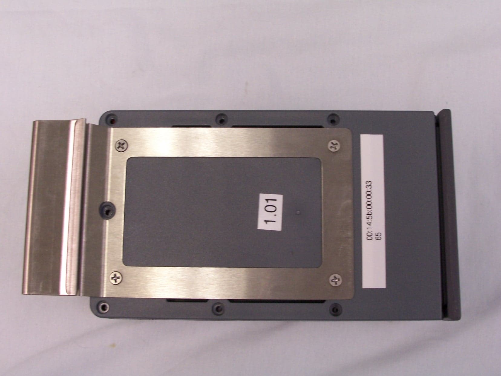
Click to zoom
Application Details
- Equipment Class
- DSS - Part 15 Spread Spectrum Transmitter
- Date of Grant
- Oct 03, 2006
- Application Purpose
- Original Equipment
- Date of Application
- Oct 03, 2006
- Equipment Note
- Spread Spectrum Transmitter
- Frequency Range
- 2402.00000000 - 2480.00000000
- Country
- United States
Documents & Files
Document Text
Text extracted from the exhibit documents filed with the FCC. Open a document above to read the original.
Users Manual
. KeyZone KZV-290 Vault Installation Guide Document number RSI290-09-00567 KeyZone KZV-290 Vault Installation Guide . KeyZone KZV-290 Vault Installation Guide Document Number: RSI290-09-00567 KeyZone is a trademark of TeraHop Networks, Inc. TeraHop Networks is a trademark of TeraHop Networks, Inc. Revision History Revision Number Date Copyright © August 21, 2006 TeraHop Networks™, Inc. All rights reserved. 1225 Old Alpharetta Rd., Suite 210 Alpharetta GA 30005 www.TeraHop.com KeyZone KZV-290 Vault Installation Guide TeraHop™ Networks, Inc. 1 1.0 Introduction The purpose of this guide is to provide installation instructions for the KeyZone Vault. 2.0 FCC Rules Compliance This equipment complies with Part 15 of the FCC rules. Any changes or modifications not expressly approved by the manufacturer could the void the user’s authority to operate the equipment. 3.0 Warnings and Cautions WARNINGS If the vehicle is going to be driven, remove the Vault from the vehicle window. Failure to do so may result in damages to the Vault or the vehicle. When using the remote to open a vault, stand so that your body is at least 20 centimeters (8 inches) away from the vault and the remote. Failure to use this device as described will result in a failure to comply with FCC rules for radio frequency (RF) exposure and is discouraged. 4.0 Installation Procedures Follow the process presented below to install the Vault on a vehicle. It is recommended that you install the Vault on the driver’s side window. 1. Lower the window on which the Vault will be mounted. See Figure 1. Figure 1 KeyZone KZV-290 Vault Installation Guide TeraHop™ Networks, Inc. 2 2. Hang the Vault outside of the window from its hanging clip. See Figure 2. Figure 2 3. Raise the window so that it is fully closed. See Figure 3. Figure 3
Block Diagram
Tag Turn-on RX TRX L 125 kHz Bluetooth RX TX RX TX SIZEFSCM NO B SCALE1 in : 1 in CSR BT 2.4 GHz PIC CPLD i-Button 26 kHz Red Green Drawer Switch Alert Tone 32 kHz 3.0 V 1.8 V Piezo Motion Sensor TeraHop Networks 1225 Old Alpharetta Rd., Suite 210 Alparetta GA 30005 RSI 290 Block Diagram FSCM NODWG NOREV 1 1 in : 1 inSHEET Drawer Latch Solinoid Drawer Switch Alert Tone 4.5 V RSI290-06-00647
ID Label/Location Info
Model: RSI290 FCC ID: S4MRSI290 This device complies with Part 15 of the FCC rules subject to the following two conditions: (1) This device may not cause harmful interference, and (2) This device must accept all interference received, including interference that may cause undesired operation. TeraHop Networks
ID Label/Location Info
FCC Label
Internal Photos
RSI290 Internal Pictures
Internal Photos
RSI290 PCA Internal Pictures
Operational Description
DOCUMENT NO DWG REV 1 DATE 8/10/06 SHEET 1of 1 RSI 290 Operational Description Confidential and Proprietary RSI 290 Operational Description TeraHop Networks, Inc. 1225 Old Alpharetta Road Alpharetta, GA 30005 678-455-8844 DOCUMENT NO DWG REV 1 DATE 8/10/06 SHEET 2of 2 RSI 290 Operational Description Confidential and Proprietary The KeyZone Vault is a secure plastic housing that stores the vehicle’s keys in a drop down drawer that is held in-place by a heavy gauge steel mechanical locking mechanism. It includes a rubberized metal mounting bracket that slips over the top edge of a vehicle’s door window. The Vault is covered with a rubberized boot and standoff feet that protect the vehicle from any potential damage caused by the Vault. The vehicle keys are placed inside the Vault drawer, which is then pushed upward into the Vault to lock the draw in place. There are two indicator lights on the front of the Vault whose operation is described below. To remove the keys from the Vault, the dealer personnel, using their authorized KeyZone Remote, presses the single button on the Remote while holding it approximately one inch from the front face of the Vault. When the Vault receives the signal and verifies that the proper authentication code is received, the Green LED on the front of the Vault will flash. This indicates that authorization has taken place and the user can open the Vault drawer. The sales person or other user then presses up on the bottom of the Vault. This action releases the locking mechanism and the drawer drops down exposing the vehicle’s keys. If the user’s Remote or the Vault contain the incorrect authentication keys, the Vault will not be set to open and the Red LED will flash. Whenever a Vault drawer is opened or closed, the Vault sends a message into the system and the KeyZone Server logs the event. The system maintains these records that consist of who accessed the Vault, which Vault was accessed and the associated vehicle, and what time the event occurred. The Vault also contains vibration sensor that is used as part of the security system. There are three levels of movement that are detected and sent to the server for interpretation. The first level of motion looks for minor infractions and triggers responses from the Controller and Sentinel. The second level of motion is more significant and will escalate the response from the Controller and Sentinel. The third is the most severe measurement that looks for significant shock such as an attempt to break a window and will cause the strongest programmed response from the Controller and Sentinel. The Vault also contains an internal calendar and clock that stores the alarm activation and deactivation times. Whenever any of the alarm events occurs during the activation period, the Vault sends a message to the network for processing and the triggering of the appropriate alarm message. The Dallas Semiconductor Ibutton™ ID only (unique factory-lasered 64 bit registration number) is attached to the vault RF Cover key fob to allow the vault to associate a key with an ID number. The registration number is stored in the vault and the server database. The vault will read the ID when the draw is closed to insure the correct RF cover key fob is put in place. If the wrong RF cover key fob is put in the drawer, the locking mechanism will be blocked three times but on the fourth the vault will accept the key and notify the server of the problem.
RF Exposure Info
Prediction of MPE limit at a given distance Equation from page 18 of OET Bulletin 65, Edition 97-01 where:S = power density P = power input to the antenna G = power gain of the antenna in the direction of interest relative to an isotropic radiator R = distance to the center of radiation of the antenna Maximum peak output power at antenna input terminal:15.60(dBm) Maximum peak output power at antenna input terminal:36.30780548(mW) Antenna gain(typical):0(dBi) Maximum antenna gain:1(numeric) Time Averaging:100(%) Prediction distance:20(cm) Prediction frequency:2442(MHz) MPE limit for uncontrolled exposure at prediction frequency:1(mW/cm^2) Power density at prediction frequency:0.007223(mW/cm^2) Margin of compliance:-21.4(dB) 2 4R PG S π =
Test Report
Nemko Test Report: 6L0238RUS1rev2 Applicant: TeraHop Networks, Inc. 300 Satellite Blvd. Suwanee, GA 30024 USA Equipment Under Test: RSI290 (E.U.T.) In Accordance With: FCC Part 15, Subpart C, 15.247 Frequency Hopping Transmitters Tested By: Nemko USA Inc. 802 N. Kealy Lewisville, Texas 75057-3136 Authorized By: Kevin Rose Wireless Engineer Date: July 24, 2006 Total number of pages 35 Nemko USA FCC PART 15, SUBPART C FREQUENCY HOPPING SPREAD SPECTRUM TRANSMITTER EQUIPMENT RSI290 PROJECT NO.:6L0238RUS1rev2 Page 2 of 35 Table of Contents Section 1. Summary of Test Results .....................................................................3 Section 2. Equipment Under Test (E.U.T.) ...........................................................5 Section 3. Channel Separation...............................................................................7 Section 4. Occupied Bandwidth ............................................................................9 Section 5. Time of Occupancy ............................................................................12 Section 6. Peak Power Output .............................................................................14 Section 7. Spurious Emissions (Antenna Conducted).........................................17 Section 8. Spurious Emissions (Radiated) ...........................................................20 Section 9. Test Equipment List ...........................................................................25 ANNEX A - TEST DETAILS .................................................................................26 ANNEX B - TEST DIAGRAMS.............................................................................34 Nemko USA FCC PART 15, SUBPART C FREQUENCY HOPPING SPREAD SPECTRUM TRANSMITTER EQUIPMENT RSI290 PROJECT NO.:6L0238RUS1rev2 Page 3 of 35 Section 1. Summary of Test Results Manufacturer: TeraHop Networks, Inc. Model No.: RSI290 Serial No.: None General: All measurements are traceable to national standards. These tests were conducted on a sample of the equipment for the purpose of demonstrating compliance with Part 15, Subpart C, Paragraph 15.247 for Frequency Hopping Spread Spectrum devices. Radiated tests were conducted is accordance with ANSI C63.4-2003. Radiated emissions are made on an open area test site. A description of the test facility is on file with the FCC. New Submission Production Unit Class II Permissive Change Pre-Production Unit THIS TEST REPORT RELATES ONLY TO THE ITEM(S) TESTED. THE FOLLOWING DEVIATIONS FROM, ADDITIONS TO, OR EXCLUSIONS FROM THE TEST SPECIFICATIONS HAVE BEEN MADE. See “ Summary of Test Data”. Nemko USA Inc. authorizes the above named company to reproduce this report provided it is reproduced in its entirety and for use by the company’s employees only. Any use which a third party makes of this report, or any reliance on or decisions to be made based on it, are the responsibility of such third parties. Nemko USA Inc. accepts no responsibility for damages, if any, suffered by any third party as a result of decisions made or actions based on this report. This report applies only to the items tested. Nemko USA FCC PART 15, SUBPART C FREQUENCY HOPPING SPREAD SPECTRUM TRANSMITTER EQUIPMENT RSI290 PROJECT NO.:6L0238RUS1rev2 Page 4 of 35 Summary Of Test Data NAME OF TEST PARA. NO. RESULT Powerline Conducted Emissions 15.207(a) NA Channel Separation 15.247(a)(1) Complies Time of Occupancy 15.247(a)(1)(ii) Complies 20 dB Occupied Bandwidth 15.247(a)(1) Complies Peak Power Output 15.247(b) Complies Spurious Emissions (Antenna Conducted) 15.247(c) Complies Spurious Emissions (Radiated) 15.247(c) Complies Footnotes: The device is battery powered. Nemko USA FCC PART 15, SUBPART C FREQUENCY HOPPING SPREAD SPECTRUM TRANSMITTER EQUIPMENT RSI290 PROJECT NO.:6L0238RUS1rev2 Page 5 of 35 Section 2. Equipment Under Test (E.U.T.) General Equipment Information Frequency Band: 902 – 928 MHz 2400 – 2483.5 MHz Frequency Range of Test Sample: 2402 to 2480 MHz Operating Voltage: 4.7 Vdc Number of Channels: 79 Channel Spacing: 1 MHz 20 dB Bandwidth:: 870 kHz User Frequency Adjustment: Software controlled Nemko USA FCC PART 15, SUBPART C FREQUENCY HOPPING SPREAD SPECTRUM TRANSMITTER EQUIPMENT RSI290 PROJECT NO.:6L0238RUS1rev2 Page 6 of 35 Description of EUT The Vault is unit that holds vehicle key in a secure manner. It uses BT 2.4 GHz to communicate with a system server. It is opened by the use of 127 kHz close range radio remote. It also provides motion monitor for tamper security. System Diagram Nemko USA FCC PART 15, SUBPART C FREQUENCY HOPPING SPREAD SPECTRUM TRANSMITTER EQUIPMENT RSI290 PROJECT NO.:6L0238RUS1rev2 Page 7 of 35 Section 3. Channel Separation NAME OF TEST: Channel Separation PARA. NO.: 15.247(a)(1) TESTED BY: David Light DATE: 20 July 2006 Test Results: Complies. Measurement Data: See 20 dB BW plot Measured 20 dB bandwidth: 880 kHz maximum Channel Separation: 1 MHz Equipment Used: 1626-1464 Measurement Uncertainty: +/- 1*10 -7 ppm Temperature: 22 °C Relative Humidity: 35 % Nemko USA FCC PART 15, SUBPART C FREQUENCY HOPPING SPREAD SPECTRUM TRANSMITTER EQUIPMENT RSI290 PROJECT NO.:6L0238RUS1rev2 Page 8 of 35 Test Data – Channel Separation Nemko USA FCC PART 15, SUBPART C FREQUENCY HOPPING SPREAD SPECTRUM TRANSMITTER EQUIPMENT RSI290 PROJECT NO.:6L0238RUS1rev2 Page 9 of 35 Section 4. Occupied Bandwidth NAME OF TEST: Occupied Bandwidth PARA. NO.: 15.247(a)(1)(i) TESTED BY: David Light DATE: 20 July 2006 Test Results: Complies. Measurement Data: See attached plots. Equipment Used: 1626-1464 Measurement Uncertainty: +/- 1*10 -7 ppm Temperature: 22 °C Relative Humidity: 35 % Nemko USA FCC PART 15, SUBPART C FREQUENCY HOPPING SPREAD SPECTRUM TRANSMITTER EQUIPMENT RSI290 PROJECT NO.:6L0238RUS1rev2 Page 10 of 35 Test Data – Occupied Bandwidth Lowest Channel Mid Channel Nemko USA FCC PART 15, SUBPART C FREQUENCY HOPPING SPREAD SPECTRUM TRANSMITTER EQUIPMENT RSI290 PROJECT NO.:6L0238RUS1rev2 Page 11 of 35 Test Da…
Text truncated - open the document above for the full version.
Test Report
REH Consulting, Inc. September 8, 2006 TeraHop RSI-290 Series Antenna Plots An Agilent 8714ES Network Analyzer was used in S21 mode, with the product test antenna connected to port 1, and a broadband log-periodic antenna (source), spaced 1 m away, connected to port 2. A reference dipole, well matched at 2,450 MHz, was initially mounted in place of the test antenna to calibrate the path setup prior to measurement. The antenna was evaluated in three planes of rotation. Figure 1 illustrates the orientation of each plane. Note semi-rigid coax attached to BT antenna and passed through decoupling bead for these measurements. Figure 1 Antenna Polar Plot Orientations 1 of 1 REH Consulting, Inc. September 8, 2006 TeraHop RSI-290 Series Antenna Plots Figure 2 Attachment of semi-rigid coax to board and antenna, prior to mounting in RSI- 290 case. Figure 3 Ferrite decoupling bead on coax, bottom view of RSI-290 case. 2 of 2 REH Consulting, Inc. September 8, 2006 TeraHop RSI-290 Series Antenna Plots Figure 4. Mounting for azimuth measurements Figure 5 Mounting for front elevation measurement. 3 of 3 REH Consulting, Inc. September 8, 2006 TeraHop RSI-290 Series Antenna Plots Figure 5 Mounting for side elevation measurement 4 of 4 REH Consulting, Inc. September 8, 2006 TeraHop RSI-290 Series Antenna Plots Polar radiation pattern plots were generated for each axis of rotation. The rotation direction is defined relative to the antenna drawing next to it. Data points were collected at 30° intervals of rotation. The 30 dB line represents the level of gain produced by a reference dipole – this is the 0 dBd reference line. 290 Blue Tooth Antenna, 2.4 GHz Patterns Azimuth 0 30 60 90 120 150 180 210 240 270 300 330 40 30 20 10 0 40 0 20 Vmag i Vang i side of box near ant front of unit Elevation Front 0 30 60 90 120 150 180 210 240 270 300 330 40 30 20 10 0 40 0 20 Hmag j Hang j top of box front of unit 5 of 5 REH Consulting, Inc. September 8, 2006 TeraHop RSI-290 Series Antenna Plots 290 Blue Tooth Antenna, 2.4 GHz Pattern Elevation Side 0 30 60 90 120 150 180 210 240 270 300 330 40 30 20 10 0 40 0 20 Imag k Iang k side away from antenna Top of unit 6 of 6 REH Consulting, Inc. September 8, 2006 TeraHop RSI-290 Series Antenna Plots Figure 5. BT antenna return loss network analyzer S11 plot – Azimuth Setup Antenna Gain Highest gain in any orientation measured is 2.0 dBd, measured in Elevation Side plane at 150° position. 7 of 7
Test Setup Photos
Setup Photos
Contact Information
Applicant
Greg Fletcher(Chief Financial Officer)
Technical Contact
Nemko USA, Inc.Abe Cox
[email protected]972-436-9600
802 N Kealy Ave · Lewisville, Texas · United States
Non-Technical Contact
Nemko USA, Inc.Christine Taylor
[email protected]972-436-9600
Test Firm
Nemko USA, Inc.Tom Tidwell
Technical Specifications
| # | Rule Parts | Frequency Range | Power Output |
|---|---|---|---|
| 1 | 15C | 2.40 GHz - 2.48 GHz | 36.00 mW |
Other Applications from TeraHop Networks Incorporated
S4MRSI11
Oct 03, 2006Remote Control Transmitter
Equipment Class
DSS - Part 15 Spread Spectrum Transmitter
S4MGC1000
Aug 03, 2006GATEWAY CONTROLLER
Equipment Class
DSS - Part 15 Spread Spectrum Transmitter