S4MRSI11Remote Control Transmitter
TeraHop Networks Incorporated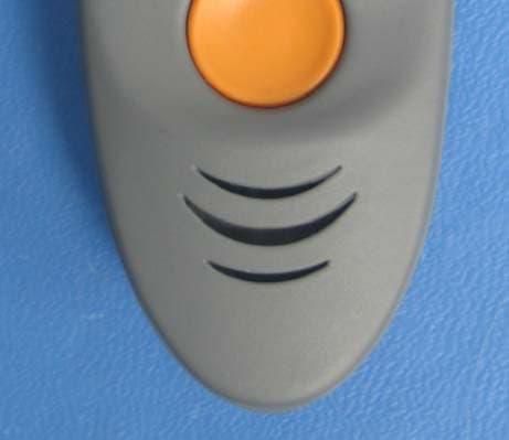
Click to zoom
Application Details
- Equipment Class
- DSS - Part 15 Spread Spectrum Transmitter
- Date of Grant
- Oct 03, 2006
- Application Purpose
- Original Equipment
- Date of Application
- Oct 03, 2006
- Equipment Note
- Remote Control Transmitter
- Frequency Range
- 2402.00000000 - 2480.00000000
- Country
- United States
Documents & Files
Document Text
Text extracted from the exhibit documents filed with the FCC. Open a document above to read the original.
Users Manual
USER INSTRUCTIONS KEYZONE REMOTE This device complies with Part 15 of the FCC rules subject to the following two conditions: (1) This device may not cause harmful interference, and (2) This device must accept all interference received, including interference that may cause undesired operation. This equipment complies with Part 15 of the FCC rules. Any changes or modifications not expressly approved by the manufacturer could the void the user’s authority to operate the equipment. RSI11-09-00622 (REV. 02) PAGE 1 OF 3 LOGIN/AUTHENTICATION KEY In the KeyZone Client Application, you must first log into the system with your name and password. Once you log in, an authentication key is sent to the Remote by the Gateway Server. The first time you press the button on the remote after logging in, both the green and red light will illuminate on the remote. Press the button on the remote again and the green light should illuminate. The green light indicates that the Gateway server has successfully assigned an authentication key to the Remote. If the red light illuminates instead, try moving the Remote to a location with a clearer line of sight to the Gateway Server and pressing the button again. If you continue to get the red light, then this indicates that the authentication key was not successfully assigned to the Remote. See Figure 1. Figure 1: Remote Lights Remote with a valid key Remote without a valid key OPENING A VAULT To use the Remote to open a KeyZone Vault, first position the Remote 1 inch or less from the Vault just beneath the rightmost light (see Figure 2). (Note: the Remote may not be able to access the Vault when the Remote and Vault are more than 1 inch apart). Press the button on the Remote and wait for one of the lights on the Vault to illuminate. If the green light on the Vault illuminates, then you have successfully accessed the Vault. You can then push upwards on the bottom of the Vault to release the car key drawer. If the red light on the Vault illuminates, then the Remote was unable to gain access to the Vault. This could indicate a problem with the Remote’s authentication key. RSI11-09-00622 (REV. 02) PAGE 2 OF 3 Figure 2: Correct Position Of Remote When Accessing A Vault For questions or assistance, please contact: TeraHop Networks, Inc. Alpharetta, GA 30005 (678) 455-8844 www.terahop.com RSI11-09-00622 (REV. 02) PAGE 3 OF 3
Block Diagram
TeraHop Networks 1225 Old Alpharetta Rd., Suite 210 Alparetta GA 30005 RSI 11 Block Diagram SIZEFSCM NODWG NOREV B1 SCALE 1 in : 1 in SHEET CSR BT 2.4 GHz PIC 26 kHz L 125 kHz Red Green Bluetooth 32 kHz RX TX RX TX 3.5 V 3.0 V RSI11-06-00584
External Photos
Picture Title: RSI11 External Document Number: RSI11-13B-00584 Issue Date: 07/07/06 Page 1 of 1 Revision: 01 Revision Date:
ID Label/Location Info
FCC ID: S4MRSI11
Internal Photos
Picture Title: RSI11 PCA Document Number: 58-00016-06 Issue Date: 07/07/06 Page 1 of 1 Revision: 02 Revision Date: Assembly: 58-00016 REV 02 Raw Board: 58-00016 REV 02 Top View Bottom View
Operational Description
DOCUMENT NO DWG REV 1 DATE 8/10/06 SHEET 1of 1 RSI 11 Operational Description Confidential and Proprietary RSI 11 Operational Description TeraHop Networks, Inc. 1225 Old Alpharetta Road Alpharetta, GA 30005 678-455-8844 DOCUMENT NO DWG REV 1 DATE 8/10/06 SHEET 2of 2 RSI 11 Operational Description Confidential and Proprietary The KeyZone Remote RSI11 is a small, handheld device that provides a single button push to access the Vaults. Each Remote contains a unique ID and is assigned to dealership personnel that need Vault access. The Remote has two indicator lights and one pushbutton switch. There are three mounting clip options that can be interchanged by the user to meet their individual carrying preferences. The clips provide the ability of the Remote to be clipped onto a person’s belt, connected to a keychain, or strung on a lanyard. The Remote’s battery is replaceable by the user. The Remote contains a Bluetooth Radio and a short-range radio (125KHz Radio). To activate a Remote for a day’s usage, the user enters their username and password into the application on a PC that communicates to the Controller via a WiFi. Once the user has logged into the system, the next press of the button will enable the Remote to communicate to the Controller to get its new authentication key. The Remote checks to see if the authentication key is up to date and will go up for a new key when the old key has expired each time the button is pressed. Otherwise the only communication is via the 125 KHz radio to the Vault RSI 290. The Remote’s LEDs illuminate based on success or failure. The Remote’s Green LED illuminates if the Remote successfully authenticates with a vault and if the Remote successfully downloads its authentication keys from the Controller. The Remote’s Red LED will illuminate upon failure of these communications. The Remote’s LEDs will now illuminate unless communications occur to conserve battery. Remote battery status will be stored in the database in a future release. The Remote Master is a Remote that has been programmed with a longer-term authentication that will enable the user to open the vault without daily verification of a logon. The purpose of this key is to enable access to the vaults in case of a system failure. The vault will still capture and log the event use of the master remote for reports
Test Report
Nemko Test Report: 6L0287RUS1rev3 Applicant: TeraHop Networks, Inc. 300 Satellite Blvd. Suwanee, GA 30024 USA Equipment Under Test: RSI11 (E.U.T.) In Accordance With: FCC Part 15, Subpart C, 15.247 Frequency Hopping Transmitters Tested By: Nemko USA Inc. 802 N. Kealy Lewisville, Texas 75057-3136 Authorized By: Kevin Rose Wireless Engineer Date: July 24, 2006 Number of pages: 35 Nemko USA FCC PART 15, SUBPART C FREQUENCY HOPPING SPREAD SPECTRUM TRANSMITTER EQUIPMENT RSI11 PROJECT NO.: 6L0287RUS1rev3 Page 2 of 35 Table of Contents Section 1. Summary of Test Results .....................................................................3 Section 2. Equipment Under Test (E.U.T.) ...........................................................5 Section 3. Channel Separation...............................................................................7 Section 4. Occupied Bandwidth ............................................................................9 Section 5. Time of Occupancy ............................................................................12 Section 6. Peak Power Output .............................................................................14 Section 7. Spurious Emissions (Antenna Conducted).........................................17 Section 8. Spurious Emissions (Radiated) ...........................................................20 Section 9. Test Equipment List ...........................................................................25 ANNEX A - TEST DETAILS .................................................................................26 ANNEX B - TEST DIAGRAMS.............................................................................34 Nemko USA FCC PART 15, SUBPART C FREQUENCY HOPPING SPREAD SPECTRUM TRANSMITTER EQUIPMENT RSI11 PROJECT NO.: 6L0287RUS1rev3 Page 3 of 35 Section 1. Summary of Test Results Manufacturer: TeraHop Networks, Inc. Model No.: RSI11 Serial No.: RSI11-0622-000027 General: All measurements are traceable to national standards. These tests were conducted on a sample of the equipment for the purpose of demonstrating compliance with Part 15, Subpart C, Paragraph 15.247 for Frequency Hopping Spread Spectrum devices. Radiated tests were conducted is accordance with ANSI C63.4-2003. Radiated emissions are made on an open area test site. A description of the test facility is on file with the FCC. New Submission Production Unit Class II Permissive Change Pre-Production Unit THIS TEST REPORT RELATES ONLY TO THE ITEM(S) TESTED. THE FOLLOWING DEVIATIONS FROM, ADDITIONS TO, OR EXCLUSIONS FROM THE TEST SPECIFICATIONS HAVE BEEN MADE. See “ Summary of Test Data”. Nemko USA Inc. authorizes the above named company to reproduce this report provided it is reproduced in its entirety and for use by the company’s employees only. Any use which a third party makes of this report, or any reliance on or decisions to be made based on it, are the responsibility of such third parties. Nemko USA Inc. accepts no responsibility for damages, if any, suffered by any third party as a result of decisions made or actions based on this report. This report applies only to the items tested. Nemko USA FCC PART 15, SUBPART C FREQUENCY HOPPING SPREAD SPECTRUM TRANSMITTER EQUIPMENT RSI11 PROJECT NO.: 6L0287RUS1rev3 Page 4 of 35 Summary Of Test Data NAME OF TEST PARA. NO. RESULT Powerline Conducted Emissions 15.207(a) NA Channel Separation 15.247(a)(1) Complies Time of Occupancy 15.247(a)(1)(ii) Complies 20 dB Occupied Bandwidth 15.247(a)(1) Complies Peak Power Output 15.247(b) Complies Spurious Emissions (Antenna Conducted) 15.247(c) Complies Spurious Emissions (Radiated) 15.247(c) Complies Footnotes: The device is battery powered. Nemko USA FCC PART 15, SUBPART C FREQUENCY HOPPING SPREAD SPECTRUM TRANSMITTER EQUIPMENT RSI11 PROJECT NO.: 6L0287RUS1rev3 Page 5 of 35 Section 2. Equipment Under Test (E.U.T.) General Equipment Information Frequency Band: 902 – 928 MHz 2400 – 2483.5 MHz Frequency Range of Test Sample: 2402 to 2480 MHz Operating Voltage: 3.6 Vdc Number of Channels: 79 Channel Spacing: 1 MHz 20 dB Bandwidth:: 880 kHz User Frequency Adjustment: Software controlled Nemko USA FCC PART 15, SUBPART C FREQUENCY HOPPING SPREAD SPECTRUM TRANSMITTER EQUIPMENT RSI11 PROJECT NO.: 6L0287RUS1rev3 Page 6 of 35 Description of EUT The EUT is a key fob remote used to access a vault used for storing automobile keys in dealership parking lots. The remote is placed next to the vault and the button is pushed to activate the 127 kHz low power radio. The remote transmits an authorization code via Bluetooth to the vault. If the remote has successfully unlocked the vault, a green LED lights. System Diagram Nemko USA FCC PART 15, SUBPART C FREQUENCY HOPPING SPREAD SPECTRUM TRANSMITTER EQUIPMENT RSI11 PROJECT NO.: 6L0287RUS1rev3 Page 7 of 35 Section 3. Channel Separation NAME OF TEST: Channel Separation PARA. NO.: 15.247(a)(1) TESTED BY: David Light DATE: 20 July 2006 Test Results: Complies. Measurement Data: See 20 dB BW plot Measured 20 dB bandwidth: 880 kHz maximum Channel Separation: 1 MHz Equipment Used: 1626-1464 Measurement Uncertainty: +/- 1*10 -7 ppm Temperature: 22 °C Relative Humidity: 35 % Nemko USA FCC PART 15, SUBPART C FREQUENCY HOPPING SPREAD SPECTRUM TRANSMITTER EQUIPMENT RSI11 PROJECT NO.: 6L0287RUS1rev3 Page 8 of 35 Test Data – Channel Separation Nemko USA FCC PART 15, SUBPART C FREQUENCY HOPPING SPREAD SPECTRUM TRANSMITTER EQUIPMENT RSI11 PROJECT NO.: 6L0287RUS1rev3 Page 9 of 35 Section 4. Occupied Bandwidth NAME OF TEST: Occupied Bandwidth PARA. NO.: 15.247(a)(1)(i) TESTED BY: David Light DATE: 20 July 2006 Test Results: Complies. Measurement Data: See attached plots. Equipment Used: 1626-1464 Measurement Uncertainty: +/- 1*10 -7 ppm Temperature: 22 °C Relative Humidity: 35 % Nemko USA FCC PART 15, SUBPART C FREQUENCY HOPPING SPREAD SPECTRUM TRANSMITTER EQUIPMENT RSI11 PROJECT NO.: 6L0287RUS1rev3 Page 10 of 35 Test Data – Occupied Bandwidth Lowest Channel Mid Channel Nemko USA …
Text truncated - open the document above for the full version.
Test Report
REH Consulting, Inc. September 7, 2006 TerHop RSI-11 Series Antenna Plots An Agilent 8714ES Network Analyzer was used in S21 mode, with the product test antenna (test) connected to port 1, and a broadband log-periodic antenna (source), spaced 1m away, connected to port 2. A reference dipole, well matched at 2,450 MHz, was initially mounted in place of the test antenna to calibrate the path setup prior to measurement. The antenna was evaluated in three planes of rotation. Figure 1 illustrates the orientation of each plane. Note semi-rigid coax attached to BT antenna and passed through decoupling bead for these measurements. Figure 1 Antenna Polar Plot Orientations 1 of 1 REH Consulting, Inc. September 7, 2006 TerHop RSI-11 Series Antenna Plots Figure 2 Log-periodic (source) and test antenna. System path loss was calibrated with a reference dipole prior to DUT measurement. 2 of 2 REH Consulting, Inc. September 7, 2006 TerHop RSI-11 Series Antenna Plots Figure 3. Test Setup for Azimuth Measurement 3 of 3 REH Consulting, Inc. September 7, 2006 TerHop RSI-11 Series Antenna Plots Figure 4 Elevation Across Plane of Board Test Setup 4 of 4 REH Consulting, Inc. September 7, 2006 TerHop RSI-11 Series Antenna Plots Figure 5 In Plane Elevation Measurement Test Setup 5 of 5 REH Consulting, Inc. September 7, 2006 TerHop RSI-11 Series Antenna Plots Polar radiation pattern plots were generated via Mathcad for each axis of rotation. The rotation direction is defined relative to the antenna drawing next to it. Data points were collected at 30° intervals of rotation. The 30 dB line represents the level of gain produced by a reference dipole – this is the 0 dBd reference line. RSI-11 Blue Tooth Antenna, 2.4 GHz Patterns Azimuth 0 30 60 90 120 150 180 210 240 270 300 330 40 30 20 10 0 40 0 20 Vmag i Vang i g ant surfa normal to A n t e n n a B o a r d Elevation Across Plane 0 30 60 90 120 150 180 210 240 270 300 330 40 30 20 10 0 40 0 20 Hmag j Hang j g ant nor B o a r d S h i e l d A n t e n n a 6 of 6 REH Consulting, Inc. September 7, 2006 TerHop RSI-11 Series Antenna Plots RSI-11 Blue Tooth Antenna, 2.4 GHz Pattern Elevation In Plane 0 30 60 90 120 150 180 210 240 270 300 330 40 30 20 10 0 40 0 20 Imag k Iang k g 7 of 7 REH Consulting, Inc. September 7, 2006 TerHop RSI-11 Series Antenna Plots Figure 5. Return loss network analyzer S11 plot – Azimuth Setup Antenna Gain Highest gain in any orientation measured is -4.7 dBd. 8 of 8
Contact Information
Applicant
Greg Fletcher(Chief Financial Officer)
Technical Contact
Non-Technical Contact
Nemko USAChristine Taylor
[email protected]972-436-9600
Test Firm
Nemko USA, Inc.Tom Tidwell
Technical Specifications
| # | Rule Parts | Frequency Range | Power Output |
|---|---|---|---|
| 1 | 15C | 2.40 GHz - 2.48 GHz | 17.00 mW |
Other Applications from TeraHop Networks Incorporated
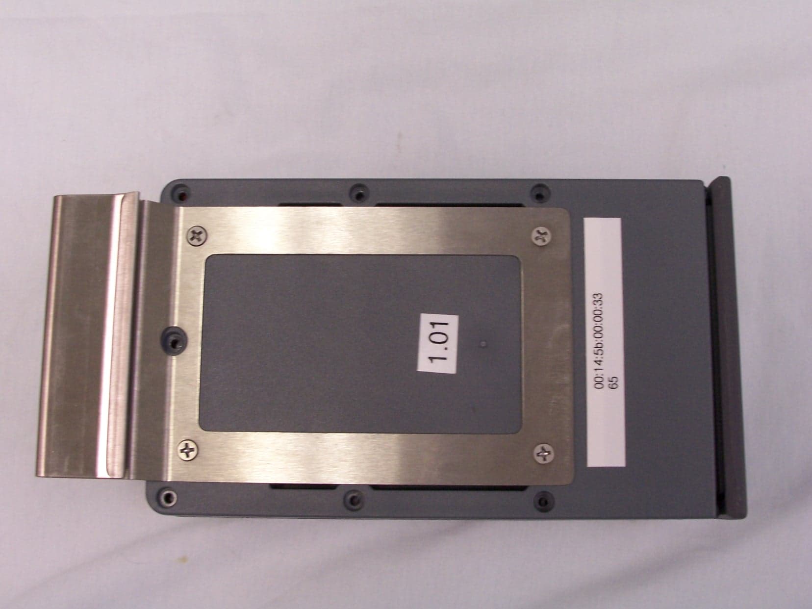
S4MRSI290
Oct 03, 2006Spread Spectrum Transmitter
Equipment Class
DSS - Part 15 Spread Spectrum Transmitter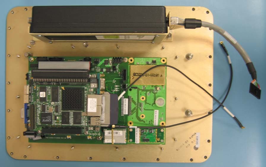
S4MGC1000
Aug 03, 2006GATEWAY CONTROLLER
Equipment Class
DSS - Part 15 Spread Spectrum Transmitter