S4PBC02ATHE-01BLUETOOTH HEADSET
Shenzhen Micah Eletronics Corp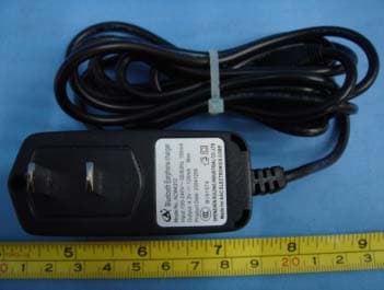
Click to zoom
Application Details
- Equipment Class
- DSS - Part 15 Spread Spectrum Transmitter
- Date of Grant
- Apr 18, 2005
- Application Purpose
- Original Equipment
- Date of Application
- Apr 18, 2005
- Equipment Note
- BLUETOOTH HEADSET
- Frequency Range
- 2400.00000000 - 2483.50000000
- Country
- China
Documents & Files
Document Text
Text extracted from the exhibit documents filed with the FCC. Open a document above to read the original.
Users Manual
USER MANUAL BLUETOOTH HEADSET Introduction Congratulations and thank you for choosing Bluetooth Headset. It is a cordless, Hands Free headset solution for Bluetooth equipped mobile phones. What is Bluetooth Wireless Technology? Bluetooth is a wireless protocol for audio and data communication between devices within a small distance of about 10m (33 ft). It uses the 2.4GHz international free spectrum to make 1Mbit connection links. It is a popular solution for replacing wire connections. Products with Bluetooth technology must be qualified and pass interoperability testing by the Bluetooth Special Interest Group prior to release. How to Use Your Headset? Your wireless headset lets you connect with other devices that have integrated Bluetooth technology. Your headset allows you to: (1) Use your Bluetooth equipped mobile phone Hands Free, especially when driving. (2) Handle incoming and outgoing calls with the headset multifunction control button (MFB). (3) Use voice activation to make and receive calls with mobile phones that support voice dialing and activation. NOTE: The Headset supports both Headset and Hands Free Bluetooth Profiles for increased functionality and compatibility with more products. Please consult your phone user’s guide for more information. Operating Your Headset Overview Please make sure that your mobile phone or equipment has compatible Bluetooth functionality. Headset Features 5 6 7 8 9 4 3 2 1 1 MFB Multi Function Button. 2 Charging port Battery Charger Socket. 3 SW1 Adjusts speaker volume up. 4 SW2 Adjusts speaker volume down. 5 LED 1 Red LED. 6 LED 2 Yellow LED. 7 Speaker Sound Reproduction. 8 Microphone Voice input. 9 Earhook Attaches headset to ear. Charging Your Headset First Time Use - Please charge the headset for 20 hours before the first use to properly condition the built-in Li-ion battery. Recharging When you hear 5 rapid beeps through the headset speaker, repeated at 20-second intervals, the headset has about 10 minutes power left. The headset battery should be recharged as soon as possible. After the battery is fully charged, the indicator LED on the charger will turn to green. It takes about 1.5 hours to fully charge the battery. Do not charge for more than 24 hours. Over extended periods of time, batteries gradually wear down and require longer charging times, this is normal. The more you talk on the phone with the headset, the less standby time your battery has. How to Charge Step 1 Plug the charger into the headset, with the charger’s release tab facing up and the headset facing down. 2 After a full charge, remove the charger from the electrical outlet, press the release tab, and detach the charger cord from the headset. NOTE: Please use only the included travel charger for charging the headset. Wearing the Headset When packaged, the headset is configured for wearing on the right ear. Step 1 Hook the headset vertically on your right ear 2 Position the speaker in your ear comfortably, and point the microphone towards your mouth. Right or Left Ear The direction of the ear clip has to be changed should you decide to wear the headset on your left ear. To Adjust the Ear Clip for Left-ear Use: Turning the Headset On or Off To turn the headset on Press and hold the headset MFB for more than 2 seconds, the headset will light up. The indicator red LED will flash 4 times. You can now use your headset. To turn the headset off Press and hold the headset MFB for more than 2 seconds, the indicator yellow LED will flash 4 times before the headset switches off. Pairing your headset and your phone [Pairing] creates a link between devices equipped with Bluetooth wireless technology and allows the phone to remember the headset’s unique ID; you could add it to a list of paired device in the phone. The headset should be paired once with the phone before use. If the pairing information or log is deleted from the phone, the headset must be paired again with the phone before use, once your headset and phone are paired, your headset can be used with your phone. Step 1 While the headset is on, press and hold the MFB till the red LED/yellow LED flash alternatively, the headset is now in pairing mode. 2 Perform a device discovery from the phone according to its manual. 3 Select [PIONEER EXTRA] from the discovered devices list and confirm the on-screen prompts. 4 When prompted by the phone, enter the passkey [1234] and the headset will confirm a successful pairing with the red/yellow LED flashing 4 times. NOTE: 1 make sure the headset and the device you are using with are no more than 10m/33 ft. apart, so they are within operable range. 2 If the headset is not successfully paired within 1 minute, it will automatically leave pairing mode. If you want to continue pairing, please start pairing mode again. For details on device discovery for your phone, please refer to the user’s guide for the phone. Volume Adjustment Headset speaker volume can be adjusted during a call. To adjust the speaker volume SW1 SW2 To turn up the volume, press the headset SW1. To turn down the volume, press the headset SW2. Placing and Receiving Calls Your headset supports both Hands Free and Headset Profiles. Accessing call functions depend on which profile the phone supports. You can activate call function with Hands Free and Headset Profiles according to the following table: NOTE: 1. Some phones do not support all features listed. Please Consult your phone user’s guide. 2. The MFB button is activated by short and long presses. A short press refers to duration of less than 1 second. A long press refers to duration of more than 1 second. After a short press, you should hear 1 beep to confirm the operation. After a long press for more than 1 second, you should hear 1 beep, releasing the button confirms the operation. Device Status Action Function Phone Headset Hand Free profiles Headset Profiles Enter pairing mode On On Long press MFB till the red LED/yellow LED flash alternatively Leave pairing mode On On…
Text truncated - open the document above for the full version.
Block Diagram
TX Li-battery MIC Crystal 16MHz Mierdcontroller RF synthesiser Baseband andlogio MOD DSP PA Balun filter RX filter Balun Li-battery SPK Crystal 16MHz Mierdcontroller RF synthesiser Baseband andlogio MOD DSP LNA
External Photos
EUT – External Photos View 2.1 EUT - Front View 2.2 EUT - Back View Adaptor - Front View Adaptor - Back View
ID Label/Location Info
FCC ID Label Location This device complies with Part 15 of the FCC Rules. Operation is subject to the following two conditions:(1) this device may not cause harmful interference, and (2) this device must accpt any interference received, including interference that may cause undesired operation The Label must not be a stick-on paper. The Label on these products must be permanently affixed to the product and readily visible at the time of purchase and must last the expected lifetime of the equipment not be readily detachable. Proposed Label Location on EUT EUT Bottom View/proposed FCC Mark Location For Home or Office Use
ID Label/Location Info
FCC ID Label Sample for Model BC02ATHE-01 FCC ID: S4PBC02ATHE-01 Made in China This device complies with Part 15 of the FCC Rules.
Internal Photos
2.1 PCB - Component View(1) 2.2 PCB - Component View(2) 2.3 PCB - Back View
Operational Description
BLUETOOTH HEADSETBlock Diagram Description TX block diagram description: The control signals and data in the BC02-AUDIO is modulated and processed and pass the PA in the chip. They output from the chip and through the Balun and Filter. Last they will be transmitted from ANT to another Bluetooth device. RX block diagram description: The RF signal from other Bluetooth device is received via ANT. And they through filter and balun into the BC02-AUDIO chip. They are magnified by internal LNA in the chip.
Test Report
FCC TEST REPORT Page 1 of 36 FCC ID : S4PBC02ATHE-01 Applicant : Shenzhen Micah Electronics Corp 1/F.,Bldg.M6,Middle District, High and New Technique Industrial Garden, Shenzhen, China Equipment Under Test (EUT) : Product description : Bluetooh Model No. : BC02ATHE-01 Standards : FCC 15 Paragraph 15.205, Paragraph 15.207, Paragraph 15.209, Paragraph 15.31, Paragraph 15.33, Paragraph 15.35, Paragraph 15.247 Date of Test : April 18, 2005 Test Engineer : Jimmy Lee Reviewed By : PERPARED BY: Shenzhen Huatongwei International Inspection Co., Ltd Keji S,12th,Road, Hi-tech Industrial Park, Shenzhen, Guangdong, China FCC Registration Number: 662850 Shenzhen Micah Electronics Corp FCC ID:S4PBC02ATHE-01 2 Contents Page 1 COVER PAGE..........................................................................................................................................................1 2 CONTENTS..............................................................................................................................................................2 3 TEST SUMMARY....................................................................................................................................................5 4 GENERAL INFORMATION..................................................................................................................................5 4.1 CLIENT INFORMATION............................................................................................................................................5 4.2 GENERAL DESCRIPTION OF E.U.T...........................................................................................................................5 4.3 DETAILS OF E.U.T..................................................................................................................................................5 4.4 DESCRIPTION OF SUPPORT UNITS...........................................................................................................................5 4.5 STANDARDS APPLICABLE FOR TESTING..................................................................................................................5 4.6 TEST FACILITY........................................................................................................................................................6 4.7 TEST LOCATION......................................................................................................................................................6 5 EQUIPMENT USED DURING TEST...................................................................................................................7 6 CONDUCTED EMISSION TEST..........................................................................................................................8 6.1 TEST EQUIPMENT....................................................................................................................................................8 6.2 TEST PROCEDURE...................................................................................................................................................8 6.3 CONDUCTED TEST SETUP.......................................................................................................................................9 6.4 EUT OPERATING CONDITION.................................................................................................................................9 6.5 CONDUCTED EMISSION LIMITS.............................................................................................................................10 6.6 CONDUCTED EMISSION TEST RESULT...................................................................................................................11 6.7 CONDUCTIED EMISSIONS TEST DATA...................................................................................................................12 7 RADIATION EMISSION TEST...........................................................................................................................13 7.1 TEST EQUIPMENT..................................................................................................................................................13 7.2 MEASUREMENT UNCERTAINTY.............................................................................................................................13 7.3 TEST PROCEDURE.................................................................................................................................................13 7.4 RADIATED TEST SETUP.........................................................................................................................................14 7.5 SPECTRUM ANALYZER SETUP...............................................................................................................................14 7.6 CORRECTED AMPLITUDE & MARGIN CALCULATION............................................................................................15 7.7 SUMMARY OF TEST RESULTS................................................................................................................................15 7.8 EUT OPERATING CONDITION...............................................................................................................................16 7.9 RADIATED EMISSIONS LIMIT.................................................................................................................................16 7.10 RADIATED EMISSIONS TEST RESULT................................................................................................................17 8 MAXIMUM PEAK OUTPUT POWER...............................................................................................................20 9 HOPPING CHANNEL NUMBER........................................................................................................................21 10 CARRIER FREQUENCIES SEPARATED....................................…
Text truncated - open the document above for the full version.
Test Setup Photos
Test Setup Photos Conduction Emission Test View For 0.15MHz-30MHz Radiation Emission Test View For 30MHz-1000MHz Radiation Emission Test View For 1GHz-25GHz
Contact Information
Applicant
Boyang Xie(Quality engineer)
Test Firm
Shenzhen Huatongwei International Insp. Co., LtdMoffy Yu
Technical Specifications
| # | Rule Parts | Frequency Range | Power Output |
|---|---|---|---|
| 1 | 15C | 2.40 GHz - 2.48 GHz | 100.00 µW |
Other Applications from Shenzhen Micah Eletronics Corp
S4PBC03RUT1-01
Sep 08, 2005USB DONGLE
Equipment Class
DSS - Part 15 Spread Spectrum Transmitter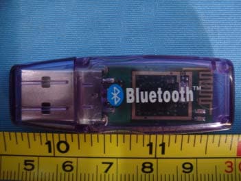
S4PBC03RUT-01
Apr 21, 2005Bluetooth USB Dongle
Equipment Class
DSS - Part 15 Spread Spectrum Transmitter