S6J1059Multi ISO RFID Reader
Technology Solutions (UK) Ltd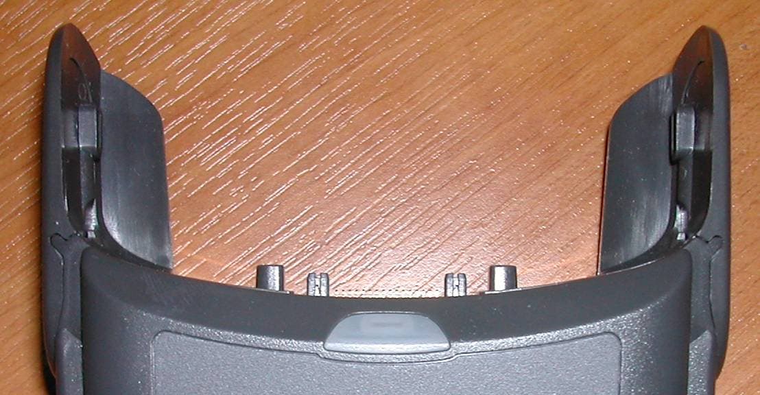
Click to zoom
Application Details
- Equipment Class
- DXX - Part 15 Low Power Communication Device Transmitter
- Date of Grant
- Jan 16, 2007
- Application Purpose
- Original Equipment
- Date of Application
- Oct 30, 2006
- Equipment Note
- Multi ISO RFID Reader
- Frequency Range
- 13.56000000 - 13.56000000
- Country
- United Kingdom
Documents & Files
Document Text
Text extracted from the exhibit documents filed with the FCC. Open a document above to read the original.
Users Manual
Multi ISO RFID 1059 User Guide.doc Multi ISO RFID 1059 User Guide Technology Solutions UK Ltd Suite C Loughborough Technology Centre Epinal Way Loughborough Leics LE11 3GE Tel: +44 (0) 1509 238248 Fax: +44 (0) 1509 220020 Email: [email protected] Multi ISO RFID 1059 User Guide.doc1059 Page 2 of 22 © 2006 TSL. All rights reserved. No part of this publication may be reproduced or used in any form, or by any electrical or mechanical means, without permission in writing from Technology Solutions (UK) Ltd. This includes electronic or mechanical means, such as photocopying, recording, or information storage and retrieval systems. The material in this manual is subject to change without notice. Technology Solutions (UK) Ltd (TSL) reserves the right to make changes to any product to improve reliability, function, or design. TSL does not assume any product liability arising out of, or in connection with, the application or use of any product, circuit, or application described herein. No license is granted, either expressly or by implication, estoppel, or otherwise under any patent right or patent, covering or relating to any combination, system, apparatus, machine, material, method, or process in which TSL products might be used. An implied license exists only for equipment, circuits, and subsystems contained in TSL products. TSL and the TSL logo are registered trademarks of TSL. Other product names mentioned in this manual may be trademarks or registered trademarks of their respective companies and are hereby acknowledged. All software is provided strictly on an “as is” basis. All software, including firmware, furnished to the user is on a licensed basis. TSL grants to the user a non-transferable and non-exclusive license to use each software or firmware program delivered hereunder (licensed program). Except as noted below, such license may not be assigned, sublicensed, or otherwise transferred by the user without prior written consent of TSL. No right to copy a licensed program in whole or in part is granted, except as permitted under copyright law. The user shall not modify, merge, or incorporate any form or portion of a licensed program with other program material, create a derivative work from a licensed program, or use a licensed program in a network without written permission from TSL. The user agrees to maintain TSL’s copyright notice on the licensed programs delivered hereunder, and to include the same on any authorized copies it makes, in whole or in part. The user agrees not to decompile, disassemble, decode, or reverse engineer any licensed program delivered to the user or any portion thereof. TSL reserves the right to make changes to any software or product to improve reliability, function, or design. TSL does not assume any product liability arising out of, or in connection with, the application or use of any product, circuit, or application described herein. Symbol is a registered trademark of Symbol Technologies, Inc. Multi ISO RFID 1059 User Guide.doc1059 Page 3 of 22 Contents 1Introduction............................................................................................................................... 4 2Parts of the RFID 1059............................................................................................................ 4 3Attaching to an MC70............................................................................................................... 5 4Detaching from an MC70......................................................................................................... 6 5Using the RFID 1059................................................................................................................ 7 5.1Basic operation................................................................................................................. 7 5.2Software support for the RFID 1059................................................................................ 9 5.2.1Low level command set............................................................................................ 9 5.2.2API.............................................................................................................................. 9 5.3Power management with the RFID 1059........................................................................ 9 5.4Fitting a SAM................................................................................................................... 10 5.5Compatible peripherals.................................................................................................. 11 5.6ActiveSync....................................................................................................................... 11 6Troubleshooting and Maintenance........................................................................................ 12 6.1Maintenance.................................................................................................................... 12 6.2Troubleshooting.............................................................................................................. 12 7Technical specifications......................................................................................................... 14 7.1Summary of specifications............................................................................................. 14 7.2Pin-outs........................................................................................................................... 17 7.3Regulatory Information................................................................................................... 18 7.4Statement of compliance................................................................................................ 19 8Health and Safety Recommendations.................................................................................. 20 9Waste Electrical and Electronic Equipment (WEEE)..............................................…
Text truncated - open the document above for the full version.
Attestation Statements
FCC Application Processing Branch Re:FCC ID S6J1059 Applicant:Technology Solutions (UK) Ltd Correspondence Reference Number:32114 731 Confirmation Number:EA335142 Response is shown in bold below: 1) Regarding reply to question 2 of preceding corresp., per FCC rules 47 CFR 2.909(a), 2.927(b), 2.931, 2.932, 2.1043, etc., applicant for FCC ID S6J1059 is responsible for FCC rules compliance when installed in end use configuration with a mobile terminal. Although not a factor in present filing, other example mobile-terminal accessories as cited in response to preceding corresp. are subject to same conditions that Class II permissive change is required if reported characteristics previously on file for associated FCC ID(s) are changed when accessory is installed. Applicant for this accessory modification is responsible to evaluate whether attachment constitutes a Class I or Class II permissive change. Please explain whether Class I or Class II permissive change is applicable when S6J1059 is operated attached to Symbol FCC IDs, eg H9PMC7004, H9PMC7070, H9PMC7090, H9PMC7094. A Class I permissive change is applicable for intended end-use configurations. The items indicated above must be submitted before processing can continue on the above referenced application. Failure to provide the requested information within 60 days of the original e-mail date may result in application dismissal pursuant to Section 2.917 (c) and forfeiture of the filing fee pursuant to section 1.1108. DO NOT reply to this e-mail by using the Reply button. In order for your response to be processed expeditiously, you must upload your response via the Internet at www.fcc.gov , Electronic Filing, OET Equipment Authorization Electronic Filing. If the response is submitted through Add Attachments, in order to expedite processing, a message which informs the processing staff that a new exhibit has been submitted must also be submitted via Submit Correspondence. Also, please note that partial responses increase processing time and should not be submitted. Any questions about the content of this correspondence should be directed to the e-mail address listed below the name of the sender.
Attestation Statements
FCC Application Processing Branch Re:FCC ID S6J1059 Applicant:Technology Solutions (UK) Ltd Correspondence Reference Number:32114 731 Confirmation Number:EA335142 Response is shown in bold below: 1) Regarding reply to question 2 of preceding corresp., per FCC rules 47 CFR 2.909(a), 2.927(b), 2.931, 2.932, 2.1043, etc., applicant for FCC ID S6J1059 is responsible for FCC rules compliance when installed in end use configuration with a mobile terminal. Although not a factor in present filing, other example mobile-terminal accessories as cited in response to preceding corresp. are subject to same conditions that Class II permissive change is required if reported characteristics previously on file for associated FCC ID(s) are changed when accessory is installed. Applicant for this accessory modification is responsible to evaluate whether attachment constitutes a Class I or Class II permissive change. Please explain whether Class I or Class II permissive change is applicable when S6J1059 is operated attached to Symbol FCC IDs, eg H9PMC7004, H9PMC7070, H9PMC7090, H9PMC7094. A Class I permissive change is applicable for intended end-use configurations. The items indicated above must be submitted before processing can continue on the above referenced application. Failure to provide the requested information within 60 days of the original e-mail date may result in application dismissal pursuant to Section 2.917 (c) and forfeiture of the filing fee pursuant to section 1.1108. DO NOT reply to this e-mail by using the Reply button. In order for your response to be processed expeditiously, you must upload your response via the Internet at www.fcc.gov , Electronic Filing, OET Equipment Authorization Electronic Filing. If the response is submitted through Add Attachments, in order to expedite processing, a message which informs the processing staff that a new exhibit has been submitted must also be submitted via Submit Correspondence. Also, please note that partial responses increase processing time and should not be submitted. Any questions about the content of this correspondence should be directed to the e-mail address listed below the name of the sender.
Cover Letter(s)
Technology Solutions (UK) Ltd Suite C, Loughborough Technology Centre Tel Number: +44 1509 238248 Epinal Way Fax Number: +44 1509 220020 LOUGHBOROUGH Company Number: 02777518 Leics VAT Number: GB 620 0306 11 LE11 3GE Certif icate No.GB2 0012 67Registration No . 004 4/1 I SO 90 01 REGI STERE D FI RM I NTERNATI ONAL ACCREDI TATI ON BOARD Attention: 2 nd November 2006 Application Examiner Re: Request for confidentiality Applicant: Technology Solutions (UK) Ltd. FCC ID: S6J1059 To whom it may concern, Permanent Confidentiality Request is hereby submitted by Technology Solutions (UK) Ltd to withhold permanently from public review certain portions of the application for equipment certification for the referenced FCC identifiers. This request for confidentiality is made pursuant to 47 CFR 0.457(d) and 0.459 of the FCC Rules. In particular, the following sections of the application are to be kept permanently confidential: Schematics (including PCB layouts and Bills of Material) Detailed Block diagrams Internal photos Rationale for request for confidentiality: Technology Solutions (UK) Ltd has invested considerable time and materials in research and development to produce the referenced product. The material contains trade secrets and confidential information that Technology Solutions (UK) Ltd does not customarily release to the public and which is otherwise not generally available to the public. Disclosure of the permanently confidential portions of this application to competitors would give them significant competitive advantages in developing similar products If you have questions or need further information, please contact the undersigned. Sincerely, Dr. David R. Evans, Managing Director Technology Solutions (UK) Ltd.
Cover Letter(s)
FCC Application Processing Branch Applicant: Technology Solutions (UK) Ltd FCC ID: S6J1059 Form 731 Confirmation Number: EA335142 Date of Original E-Mail: 01/16/2007 Correspondence Reference Number: 32413 Response is shown in bold below: 1) You requested confidentiality on internal photos. This is not permitted on this type of product. However, you can request short-term confidentiality. Please request that internal photos have short-term confidentiality or request that confidentiality be removed entirely for the internal photos. Please apply short-term confidentiality to the internal photographs. The items indicated above must be submitted before processing can continue on the above referenced application. Failure to provide the requested information within 60 days of the original e-mail date may result in application dismissal pursuant to Section 2.917 (c) and forfeiture of the filing fee pursuant to section 1.1108. DO NOT reply to this e-mail by using the Reply button. In order for your response to be processed expeditiously, you must upload your response via the Internet at www.fcc.gov, Electronic Filing, OET Equipment Authorization Electronic Filing. If the response is submitted through Add Attachments, in order to expedite processing, a message which informs the processing staff that a new exhibit has been submitted must also be submitted via Submit Correspondence. Also, please note that partial responses increase processing time and should not be submitted. Any questions about the content of this correspondence should be directed to the e-mail address listed below the name of the sender.
External Photos
1059 External Photos.doc 1059 External Photos 1059 External Photos.doc1059 Page 2 of 2 Contents 1Front view of product................................................................................................................ 3 2Rear view of product................................................................................................................ 4 3Product attached to PDA......................................................................................................... 5 History VersionDateModifications 1.002/11/06 Document Creation 1059 External Photos.doc1059 Page 3 of 3 1 Front view of product 1059 External Photos.doc1059 Page 4 of 4 2 Rear view of product 1059 External Photos.doc1059 Page 5 of 5 3 Product attached to PDA
ID Label/Location Info
1059 . Page 1 of 1 ID label The ID label is 1.8” × 0.4”. It is fixed behind a window in the main product label which is printed on 0.125mm velvet polycarbonate with a 3M 468MP adhesive backing or equivalent. The small size of the RFID reader and its identification label prevent the compliance statement from being printed on the product. The compliance statement is printed in the User Manual. ID label location The ID label is fitted to the rear of the product as shown below:
Internal Photos
1059 Internal Photos.doc 1059 Internal Photos 1059 Internal Photos.doc1059 Page 2 of 9 Contents 1Top view of RF PCB................................................................................................................. 3 2View of all PCBs....................................................................................................................... 4 3Rear view of RF Section PCB................................................................................................. 5 4Front view of Main PCB........................................................................................................... 6 5Rear view of Main PCB............................................................................................................ 7 6Front view of connector PCB................................................................................................... 8 7Rear view of connector PCB................................................................................................... 9 History VersionDateModifications 1.002/11/06 Document Creation 1059 Internal Photos.doc1059 Page 3 of 9 1 Top view of RF PCB 1059 Internal Photos.doc1059 Page 4 of 9 2 View of all PCBs RF Section PCB Main PCB Connector PCB 1059 Internal Photos.doc1059 Page 5 of 9 3 Rear view of RF Section PCB 1059 Internal Photos.doc1059 Page 6 of 9 4 Front view of Main PCB 1059 Internal Photos.doc1059 Page 7 of 9 5 Rear view of Main PCB 1059 Internal Photos.doc1059 Page 8 of 9 6 Front view of connector PCB 1059 Internal Photos.doc1059 Page 9 of 9 7 Rear view of connector PCB
RF Exposure Info
FCC Application Processing Branch Re: FCC ID S6J1059 Applicant: Technology Solutions (UK) Ltd Correspondence Reference Number: 32054 731 Confirmation Number: EA335142 Responses are shown in bold below each question: 1) Will this device be operated always and only with Symbol-MC70? Yes. The mechanical design of the S6J1059 is such that it can only connect on to a Symbol MC70. 2) As we understand, Symbol-MC70 is available with different associated transmitter options. For example, certification application filing for FCCID H9PMC7094 (800, 1900, 2400, 5300, 5800 MHz) includes SAR evaluation for held-to-ear and body-worn-accessory use conditions. In general, some metallic and/or structural changes to handsets used next to head or body can change the near-field exposure conditions and change SAR. Will the existing H9PMC7094 transmitters be capable of operating in the same near-body conditions as reported there when FCCID S6J1059 is attached to Symbol-MC70? If yes, this filing for S6J1059 attached to H9PMC7094 may need more info to support compliance demonstration for FCC RF exposure requirements. The MC70 is available in different transmitter options. The full functionality of the MC70 is retained when using the S6J1059. A range of accessories are currently available for the MC70 which represent structural and/or metallic changes to the MC70. A very similar example is the Symbol MSR7000-100R Magnetic Swipe Card Reader. This accessory attaches in the same way as the S6J1059, is a similar, small physical size and contains additional metal in the form of printed circuit board. Other accessories which represent structural and/or metallic changes are the high capacity battery (Symbol Part Number 82-71364-02) and the Pistol Grip Handle (Symbol Part Number 21-70982-01). The small size of the S6J1059 relative to the MC70 and distance from the transmitting antenna of the MC70 minimises the influence of the accessory on the SAR. Technology Solutions therefore believes that in common with the other standard Symbol accessories for the MC70, no additional SAR evaluation is required. The items indicated above must be submitted before processing can continue on the above referenced application. Failure to provide the requested information within 60 days of the original e-mail date may result in application dismissal pursuant to Section 2.917 (c) and forfeiture of the filing fee pursuant to section 1.1108. DO NOT reply to this e-mail by using the Reply button. In order for your response to be processed expeditiously, you must upload your response via the Internet at www.fcc.gov , Electronic Filing, OET Equipment Authorization Electronic Filing. If the response is submitted through Add Attachments, in order to expedite processing, a message which informs the processing staff that a new exhibit has been submitted must also be submitted via Submit Correspondence. Also, please note that partial responses increase processing time and should not be submitted. Any questions about the content of this correspondence should be directed to the e-mail address listed below the name of the sender.
Test Report
Total number of pages : 45 KTL EMC Test Report:6C9433GUS1 Applicant:Technology Solutions (UK) Limited Apparatus:1059 HF Multi ISO Readerfor the MC70 Handheld Computer Authorised by: :K. J. Anderson, Principal EMC and Radio Group Engineer. Issue Date:10 th October 2006 Authorised Copy Number: CD KTL EMC Test Report: 6C9433GUS1 2 Contents Section 1:Introduction3 1.1General3 1.2Tests Requested By4 1.3Manufacturer4 1.4Apparatus Assessed4 1.5Test Result Summary5 1.6Notes Relating To The Assessment6 1.7Deviations from Test Standards6 Section 2:Measurement Uncertainty7 2.1Introduction7 2.2Application of Measurement Uncertainty7 2.3Measurement Uncertainty Values7 Section 3:Modifications8 3.1Modifications Performed During Assessment8 Appendix A:Formal Emission Test Results9 Appendix B:Supporting Graphical Data25 Appendix C:Additional Test and Sample Details34 Appendix D:Additional Information40 Appendix E:Photographs and Figures41 KTL EMC Test Report: 6C9433GUS1 3 Section 1:Introduction 1.1General This report contains an assessment of an apparatus against Electromagnetic Compatibility Standards based upon tests carried out on samples submitted to the Laboratory. Test performed by:KTL Saxon Way Priory Park West Hull HU13 9PB United Kingdom Telephone:+44 (0) 1482 801801 Fax:+44 (0) 1482 801806 Email:[email protected] Web site:www.ktl.com Tests performed by: : M Render, Senior EMC and Radio Engineer Report author: As above This report must not be reproduced except in full without prior written permission from KTL. KTL EMC Test Report: 6C9433GUS1 4 1.2Tests Requested By This test report has been prepared on behalf of: Technology Solutions (UK) Limited Suite C Loughborough Technology Centre Epinal Way Loughborough Leicestershire United Kingdom 1.3Manufacturer As above. 1.4Apparatus Assessed The following apparatus was assessed between 03/08/06 and 19/08/06: 1059 HF Multi ISO Readerfor the MC70 Handheld Computer The above equipment was a short range scanning receiver operating at 13.56MHz. Modulation: Pulse modulation with a modulation depth of 100%. KTL EMC Test Report: 6C9433GUS1 5 1.5Test Result Summary Full details of test results are contained within Appendix A. The following table summarises the results of the assessment. The statements relating to compliance with the standards below apply ONLY as qualified in the notes and deviations stated in sections 1.6 to 1.7 of this test report. Test TypeRegulationMeasurement standardRangeResult REFE** Title 47 of the CFR:2005, Part 15 Subpart (c), Clause 15.225(a) ANSI C63.4:2003 13.553MHz to 13.567MHz Pass REFE** Title 47 of the CFR:2005, Part 15 Subpart (c), Clause 15.225(b) ANSI C63.4:2003 13.410MHz to 13.553MHz and 13.567MHz to 13.710MHz Pass REFE** Title 47 of the CFR:2005, Part 15 Subpart (c), Clause 15.225(c) ANSI C63.4:2003 13.710MHz to 14.010MHz * Pass REFE** Title 47 of the CFR:2005, Part 15 Subpart (c), Clause 15.209 (d) ANSI C63.4:200330kHz to 30MHzPass REFE Title 47 of the CFR:2005, Part 15 Subpart (c), Clause 15.209 ANSI C63.4:200330MHz to 5GHzPass PLCE Title 47 of the CFR:2005, Part 15 Subpart (c), Clause 15.207 ANSI C63.4:2003150kHz to 30MHzPass Frequency Stability Title 47 of the CFR:2005, Part 15 Subpart (c), Clause 15.225(e) ANSI C63.4:20030.01% of nominal Pass *Excluding frequency bands identified in Clauses 15.225(a), 15.225(b) and 15.225(c). **Measurements made using a screened magnetic loop antenna. Abbreviations used in the above table: CFR: Code of Federal RegulationsANSI: American National Standards Institution REFE: Radiated Electric Field Emissions PLCE: AC power conducted emissions Mod: Modification KTL EMC Test Report: 6C9433GUS1 6 1.6Notes Relating To The Assessment With regard to this assessment, the following points should be noted: The results contained in this report relate only to the items tested and were obtained inthe period between the date of initial receipt of samples and the date of issue of the report. The apparatus was set up and exercised using the configurations, modes of operation and arrangements defined in this report only. Particular operating modes, apparatus monitoring methods and performance criteria required by the standards tested to have been performed except where identified in Section 1.7 of this test report (Deviations from Test Standards). For emissions testing, throughout this test report, “Pass” indicates that the results for the sample as tested were below the specified limit (refer also to Section 2, Measurement Uncertainty). All testing with the exception of testing at the Open Area Test Site was performed under the following environmental conditions: Temperature: 17 to 23 degrees C Humidity : 45 to 75 % Barometric Pressure: 86 to 106 kPa All dates used in this report are in the format dd/mm/yy. This assessment has been performed in accordance with the requirements of ISO/IEC 17025. KTL’s facilities are listed with the Federal Communications Commission (FCC) as suitable for performing measurements in support of application for certification under parts 15 and 18 of the FCC rules: Registration number 90743. KTL Hull is a listed electromagnetic compatibility Conformance Assessment Body (CAB) for EC access to the US market. (Decision No 3/2000 of the Joint Committee established under the Agreement on Mutual Recognition between the European Community and the United States of America.This decision was effective from 16 th January 2001). 1.7Deviations from Test Standards There were no deviations from the standards tested to. KTL EMC Test Report: 6C9433GUS1 7 Section 2:Measurement Uncertainty 2.1Introduction The standard ISO/IEC 17025 used for laboratory accreditation requires laboratories to estimate measurement uncertainty using accepted methods of analysis. Where required, the reported expanded uncertainty is based on a standard uncertainty providing a confidence level of approximately 95%. Measurement uncertainty is calculated using the methods defined in the UKAS document LAB34 Edition 1 August 2002…
Text truncated - open the document above for the full version.
Test Setup Photos
1059 Test Setup Photos The Test Setup Photos are contained in the Test Report from KTL (6C9433GUS1.pdf), Appendix E, page 41 onwards.
Test Setup Photos
Total number of pages : 45 KTL EMC Test Report:6C9433GUS1 Applicant:Technology Solutions (UK) Limited Apparatus:1059 HF Multi ISO Readerfor the MC70 Handheld Computer Authorised by: :K. J. Anderson, Principal EMC and Radio Group Engineer. Issue Date:10 th October 2006 Authorised Copy Number: CD KTL EMC Test Report: 6C9433GUS1 2 Contents Section 1:Introduction3 1.1General3 1.2Tests Requested By4 1.3Manufacturer4 1.4Apparatus Assessed4 1.5Test Result Summary5 1.6Notes Relating To The Assessment6 1.7Deviations from Test Standards6 Section 2:Measurement Uncertainty7 2.1Introduction7 2.2Application of Measurement Uncertainty7 2.3Measurement Uncertainty Values7 Section 3:Modifications8 3.1Modifications Performed During Assessment8 Appendix A:Formal Emission Test Results9 Appendix B:Supporting Graphical Data25 Appendix C:Additional Test and Sample Details34 Appendix D:Additional Information40 Appendix E:Photographs and Figures41 KTL EMC Test Report: 6C9433GUS1 3 Section 1:Introduction 1.1General This report contains an assessment of an apparatus against Electromagnetic Compatibility Standards based upon tests carried out on samples submitted to the Laboratory. Test performed by:KTL Saxon Way Priory Park West Hull HU13 9PB United Kingdom Telephone:+44 (0) 1482 801801 Fax:+44 (0) 1482 801806 Email:[email protected] Web site:www.ktl.com Tests performed by: : M Render, Senior EMC and Radio Engineer Report author: As above This report must not be reproduced except in full without prior written permission from KTL. KTL EMC Test Report: 6C9433GUS1 4 1.2Tests Requested By This test report has been prepared on behalf of: Technology Solutions (UK) Limited Suite C Loughborough Technology Centre Epinal Way Loughborough Leicestershire United Kingdom 1.3Manufacturer As above. 1.4Apparatus Assessed The following apparatus was assessed between 03/08/06 and 19/08/06: 1059 HF Multi ISO Readerfor the MC70 Handheld Computer The above equipment was a short range scanning receiver operating at 13.56MHz. Modulation: Pulse modulation with a modulation depth of 100%. KTL EMC Test Report: 6C9433GUS1 5 1.5Test Result Summary Full details of test results are contained within Appendix A. The following table summarises the results of the assessment. The statements relating to compliance with the standards below apply ONLY as qualified in the notes and deviations stated in sections 1.6 to 1.7 of this test report. Test TypeRegulationMeasurement standardRangeResult REFE** Title 47 of the CFR:2005, Part 15 Subpart (c), Clause 15.225(a) ANSI C63.4:2003 13.553MHz to 13.567MHz Pass REFE** Title 47 of the CFR:2005, Part 15 Subpart (c), Clause 15.225(b) ANSI C63.4:2003 13.410MHz to 13.553MHz and 13.567MHz to 13.710MHz Pass REFE** Title 47 of the CFR:2005, Part 15 Subpart (c), Clause 15.225(c) ANSI C63.4:2003 13.710MHz to 14.010MHz * Pass REFE** Title 47 of the CFR:2005, Part 15 Subpart (c), Clause 15.209 (d) ANSI C63.4:200330kHz to 30MHzPass REFE Title 47 of the CFR:2005, Part 15 Subpart (c), Clause 15.209 ANSI C63.4:200330MHz to 5GHzPass PLCE Title 47 of the CFR:2005, Part 15 Subpart (c), Clause 15.207 ANSI C63.4:2003150kHz to 30MHzPass Frequency Stability Title 47 of the CFR:2005, Part 15 Subpart (c), Clause 15.225(e) ANSI C63.4:20030.01% of nominal Pass *Excluding frequency bands identified in Clauses 15.225(a), 15.225(b) and 15.225(c). **Measurements made using a screened magnetic loop antenna. Abbreviations used in the above table: CFR: Code of Federal RegulationsANSI: American National Standards Institution REFE: Radiated Electric Field Emissions PLCE: AC power conducted emissions Mod: Modification KTL EMC Test Report: 6C9433GUS1 6 1.6Notes Relating To The Assessment With regard to this assessment, the following points should be noted: The results contained in this report relate only to the items tested and were obtained inthe period between the date of initial receipt of samples and the date of issue of the report. The apparatus was set up and exercised using the configurations, modes of operation and arrangements defined in this report only. Particular operating modes, apparatus monitoring methods and performance criteria required by the standards tested to ha…
Text truncated - open the document above for the full version.
Contact Information
Applicant
David Evans(Founder)
Technical Contact
Technology Solutions (UK) LtdDavid Alexander Corder
[email protected]+441509238248
Suite C, Loughborough Technology Centre · Leicestershire. · United Kingdom
Test Firm
Element Materials Technology Warwick LtdKeith Wright
Technical Specifications
| # | Rule Parts | Frequency Range | Power Output |
|---|---|---|---|
| 1 | 15C | 13.56 MHz - 13.56 MHz | - |
Other Applications from Technology Solutions (UK) Ltd
S6J3128
Aug 10, 20263128 BLUETOOTH UHF RFID RAIN READER
Equipment Class
DSS - Part 15 Spread Spectrum TransmitterS6J-3417
Aug 30, 20233417 UHF RAIN RFID Reader Module
Equipment Class
DSS - Part 15 Spread Spectrum Transmitter
S6J2128L
Apr 08, 20202128L / IH21L Linear Bluetooth Handheld UHF RFID Reader
Equipment Class
DSS - Part 15 Spread Spectrum Transmitter
S6J1153
Oct 30, 20141153 Bluetooth Wearable UHF RFID Reader
Equipment Class
DSS - Part 15 Spread Spectrum Transmitter
S6J1134
Dec 18, 20111134 LF RFID READER
Equipment Class
DXX - Part 15 Low Power Communication Device Transmitter