S79FD-2100DIGITAL DOOR LOCK
Firstech I&C Co., Ltd.
Click to zoom
Application Details
- Equipment Class
- DXX - Part 15 Low Power Communication Device Transmitter
- Date of Grant
- May 10, 2005
- Application Purpose
- Original Equipment
- Date of Application
- May 10, 2005
- Equipment Note
- DIGITAL DOOR LOCK
- Frequency Range
- 13.56000000 - 13.56000000
- Company
- Firstech I&C Co., Ltd.
- Country
- South Korea
Documents & Files
Document Text
Text extracted from the exhibit documents filed with the FCC. Open a document above to read the original.
Users Manual
Operating Instructions for FD-2100 Digital Door Lock Hereby, Firstech I&C Co., Ltd., declares that FD-2100 is in com pliance with the essential requirements and other relevant provisions of Directive 1995/5/ EC Digital Door Lock CAUTION: Any changes or modifications in construction of this device whi ch are not expressly approved by the party responsible for compliance could void the user s authority to the equipment. CAUTION : Risk of Explosion if battery is replaced by an incorrect type . Dispose of used batteries according to the instructions Digital Door Lock I N D E X 1. Name of parts 4 2. Specifications 5 3. Features 6 4. Operating instruction 7 5. How to add or delete the cards 7 6. Cautions 12 7. How to install 12 8. How to use Master PIN 14 Digital Door Lock . Name of part 1) Outer body 2) Inner body Digital Door Lock 2. Specifications Specifications Model No. FD-2100 Inner: 103(H) x 158.5(W) x 40(D) mm Size Outer: 165(H) x 68(W) x 31(D) mm Power DC 6V(4 alkaline ‘AA’ batteries) Battery life 1 year (assuming 10 open/close a day) Material Die Casting (aluminum) Reading Range Within 30mm Available digits of PIN 3-20 digits Number of cards to register 1-100 cards Door thickness for installation 35-45mm Power (for emergency) DC 9V (not included) Digital Door Lock 3. Features - Imaginary numbers before the real PIN Pressing imaginary numbers (how many digits you want) before the real PIN prevents people who spy out your PIN. - Setting and modification of password (3~20 digits) You can set and modify your password at any time. -Backlighting system This feature allows you to see the keypad in low light or dark conditions than ks to self-illumination of the buttons. -Auto re-lock function If enabled, this function will lock the door within six seconds after being cl osed. The users do not have to bother locking the door after opening. -Low battery warning Red light flashes with an alarm sound to let user know when the battery is running low. Digital Door Lock -Tamper proof All functions will stop for 30 seconds if you enter the wrong password more than three times by mistake. -Easy installation The installation of this lock is simple and, in most cases, the existing keyhole can be used. Full installation instruction is supplied. -PIN memory Once the PIN is set, it will not be changed or erased even when the ba tteries are changed. -Indoor double lock system The product has an indoor double lock system preventing someone opening the door from the outside. If this function is activated, no one, even with the correct PIN, can open the door from outside. -Outdoor double lock system The user can use this feature from the outside. If the “Lock Button” is held down for 3 seconds after locking the door, no one can open the door from inside. Digital Door Lock 4. Operating instruction -How to set up Personal Identification Number NOTE: All procedures have to be done in 8 seconds. Digital Door Lock -How to open the door using PIN from outside -How to open the door from inside Digital Door Lock -How to close the door when Auto-relock is activated The lock will automatically lock the door after being closed thanks to the magnetic sensor. NOTE: The lock will lock the door 6 seconds after the valid PIN or smart key are input. -How to close the door when Auto-relock is not activated -How to set automatic lock option Digital Door Lock -How to set on/off double lock from inside On (Red) The door remains locked despite of inputting PIN or smart keys Off -How to set on/off double lock from outside *How to set on 1) Press the “Lock Button” on outer body for 5 seconds 2) The double locking function will be activated and the open/close key in the inner side will not work. *How to set off It will open only by PIN or smart key from the outside. *** This function is especially good when no one is in or going out for a long time. -Ports for emergency Digital Door Lock 5. How to add or delete the cards You can open this lock by cards, key tags or “pass-watch” supplied with the system. -How to register the smart keys (up to 50 smart keys) -How to open the door using smart keys Digital Door Lock - How to delete and add smart keys when lost Press “Card Setup Key” Press “0” key twice Now, all the smart keys are deleted. *** Enroll the new smart keys by following Step 1 or 2. -How to set the buzzer on/off Digital Door Lock 6. Cautions -If water gets in the device, wipe out the water with a dry towel. It may cause a malfunction. -If the blue LED flashes when you press the lock key or “ key, that means the batteries are running low. Please change batteries to new ones quickly. (Battery life – approx. 1 year / alkaline batteries) -We strongly recommend that you press imaginary num bers before the real PIN wh en a stranger is nearby. -Do not use rechargeable batteries. -Even if PIN is changed, the regi stered cards are to remain the same . Burglar Alarm System -The noisy alarm will sound if someone tries to open the door with force. -Once the alarm goes off, only the registered card or inputting va lid PIN will cancel the alarm. -This Burglar Alarm System is installe d in the factory as a default. If you wish it to be set off, please follow the procedures below, Press key twice ((Beep) Digital Door Lock -To set the Burglar Alarm System on again, follow the 1) , 2) procedures and the Burglar Alarm System will be installed with the sound of "Beep-Beep-Beep". Press key twice ((Beep) Digital Door Lock 7. How to install Digital Door Lock Digital Door Lock
External Photos
Photographs of EUT (External) Front View Rear View Side View (Main body & Keypad)
ID Label/Location Info
Sample Label & Location Model Name: Digital Door Lock Model: FD-2100 Power: 6V , 150mA (Alkaline battery 1.5V x 4EA) This device complies with part 15 of the FCC Rules. Operation is subject to the following two conditions; (1) this device may not cause harmful interference, and (2) this device must accept any interference received, including interference that may cause undesired operation. FCC ID: S79FD-2100 Freq. Band: 13.56MHz FIRSTECH I&C CO., LTD. Made in Korea
Internal Photos
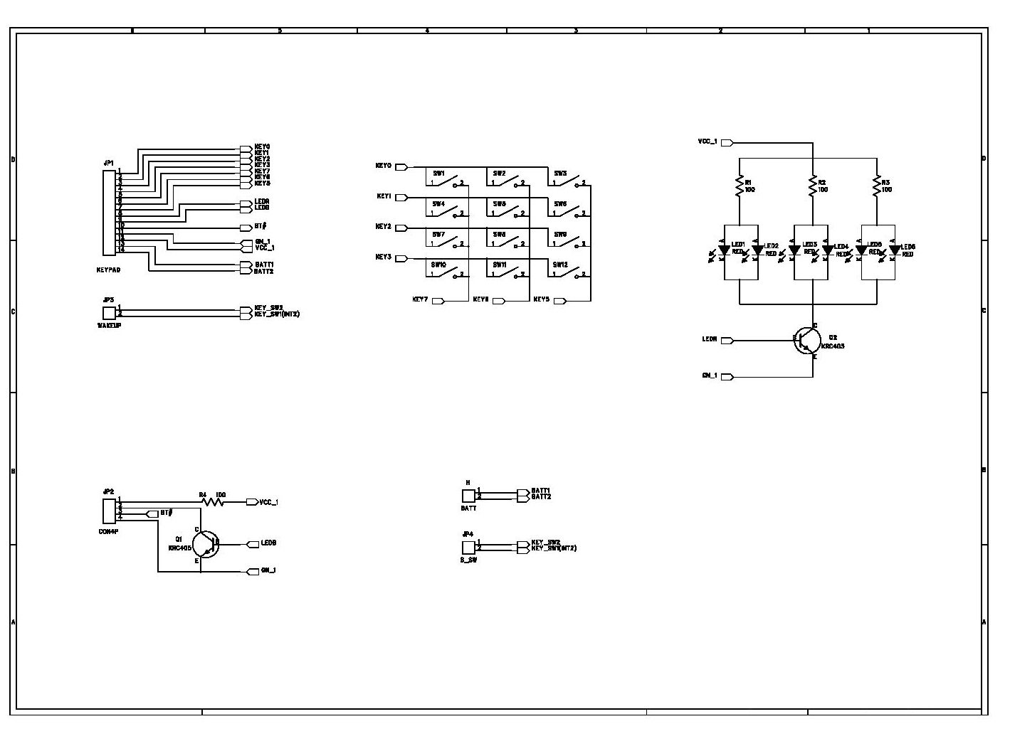
Photograph of EUT (Internal) Inside view – Main body Inside view - Keypad Mainboard ( Components side & Copper side)
Operational Description
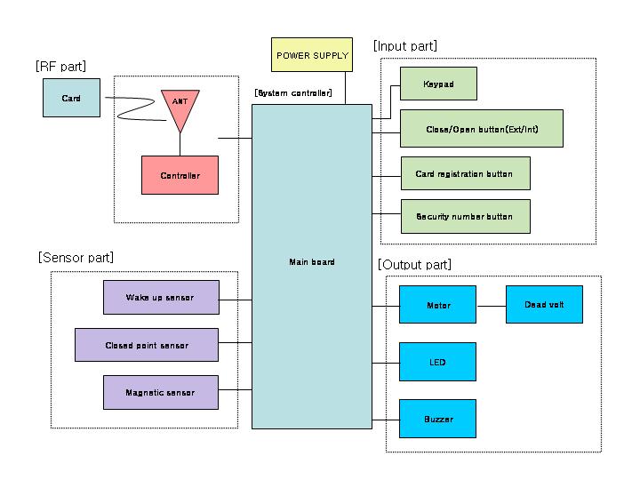
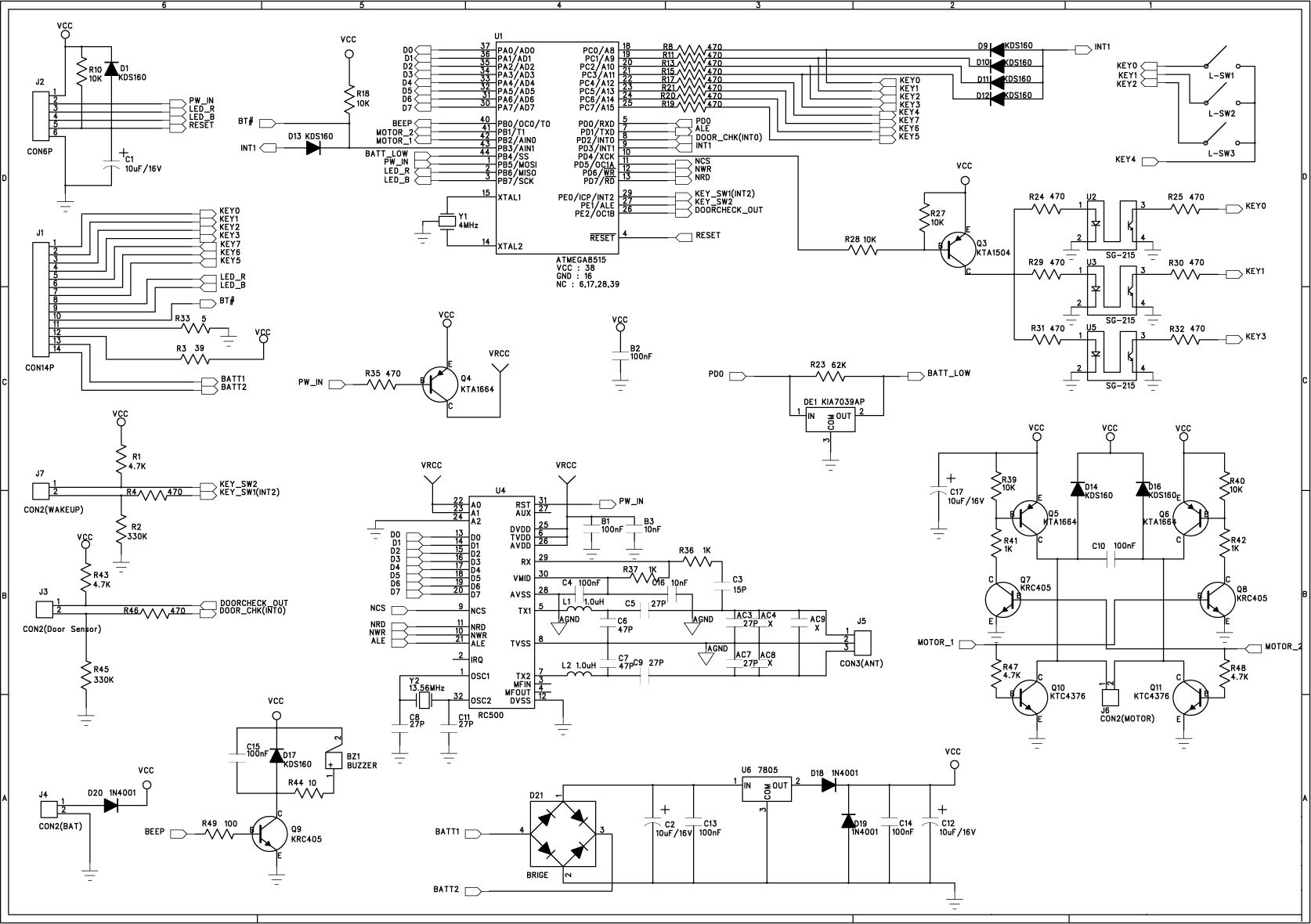
Circuit descriptions of Digital Door Lock FD-2100 Step 1: Sleep mode A This mode means awaiting for sensing material approach. (Photo coupler(U2) is cutoff state and U3 maintains checking the sensing RF-card approach.) Step 2: Wake-up mode This mode means period of the system goes into the operation status after detection sensing RF-card. (Power switching TR(Q4) is turned-on and this logic level drives the RF generation device IC(U4: RC-500). RF 13.56Mhz signal is triggered and transmitted to the RF antenna terminal by this logic level on and off, simultaneously.) Step 3: Operation mode If the sensing RF card approaches to this terminal, the inductive RF current in RF-card makes the chip in this card generates its own ID & data which will be interpreted by CPU. This data is transferred to the CPU (ATmega8515) which compares two data whether input data is correct with registered data in memory or not. If the data coincides with registered data then CPU sends the command to motor driver(Q10) that let the action motor releases the locking arm. Same time, door sensor detects the states of door opened and it sends the detection data to the CPU. Step 4: Sleep mode B After door open status, memorized melody signal drives the audio amplifier(Q9) that makes the alarm buzzer rings. Then Digital Door Lock goes into the sleep mode again. Attached: circuit diagram of FD-2100
Test Report
TIMCO ENGINEERING INC. 849 NW State Road 45 Newberry, Florida 32669 http://www.timcoengr.com 888.472.2424 F 352.472.2030 email: [email protected] APPLICANT: FIRSTECH I&C CO., LTD. FCC ID: S79FD-2100 REPORT #: U:\F\FIRSTECH\649UT5\649UT5TestReport.doc COVER SHEET Test Report Product Name: DIGITAL DOOR LOCK FCC ID: S79FD-2100 Applicant: FIRSTECH I&C CO., LTD. B105, B-DONG, WOOLIM LION'S VALLEY 1 371-28, GASAN-DONG, KUMCHON-GU SEOUL, KOREA Date Receipt: 3/29/2005 Date Tested: 4/1/2005 TIMCO ENGINEERING INC. 849 NW State Road 45 Newberry, Florida 32669 http://www.timcoengr.com 888.472.2424 F 352.472.2030 email: [email protected] APPLICANT: FIRSTECH I&C CO., LTD. FCC ID: S79FD-2100 REPORT #: U:\F\FIRSTECH\649UT5\649UT5TestReport.doc TABLE OF CONTENTS TABLE OF CONTENTS APPLICANT: FIRSTECH I&C CO., LTD. FCC ID : S79FD-2100 TEST REPORT CONTAINING: PAGE 1...............TEST EQUIPMENT LIST PAGE 2...............TEST PROCEDURE PAGE 3-4.............RADIATION INTERFERENCE TEST DATA PAGE 5...............FREQUENCY STABILITY TEST DATA PAGE 6...............OCCUPIED BANDWIDTH PAGE 7...............OCCUPIED BANDWIDTH PLOT EXHIBITS INCLUDING: BLOCK DIAGRAM INSTRUCTION MANUAL FCC ID LABEL SAMPLE AND LOCATION EXTERNAL PHOTOS INTERNAL PHOTOS OPERATIONAL DESCRIPTION TEST SET UP PHOTO TIMCO ENGINEERING INC. 849 NW State Road 45 Newberry, Florida 32669 http://www.timcoengr.com 888.472.2424 F 352.472.2030 email: [email protected] APPLICANT: FIRSTECH I&C CO., LTD. FCC ID: S79FD-2100 REPORT #: U:\F\FIRSTECH\649UT5\649UT5TestReport.doc Page 1 of 7 Equipment List Device Manufacturer Model Serial Number Cal/Char Date Due Date 3/10-Meter OATS TEI N/A N/A Listed 3/27/04 3/26/07 3-Meter OATS TEI N/A N/A Listed 1/13/03 1/12/06 Biconnical Antenna Eaton 94455-1 1057 CAL 3/18/03 3/18/05 Biconnical Antenna Eaton 94455-1 1096 CAL 8/17/04 8/17/06 Biconnical Antenna Electro- Metrics BIA-25 1171 CAL 4/29/05 4/29/07 Blue Tower Quasi-Peak Adapter HP 85650A 2811A01279 CAL 4/13/05 4/13/07 Blue Tower RF Preselector HP 85685A 2926A00983 CAL 4/13/05 4/13/07 Blue Tower Spectrum Analyzer HP 8568B 2928A04729 2848A18049 CAL 4/13/05 4/13/07 LISN Electro- Metrics ANS-25/2 2604 CAL 8/27/04 8/27/06 LISN Electro- Metrics EM-7820 2682 CAL 4/28/05 4/28/07 Log- Periodic Antenna Eaton 96005 1243 CAL 5/8/03 5/8/05 TIMCO ENGINEERING INC. 849 NW State Road 45 Newberry, Florida 32669 http://www.timcoengr.com 888.472.2424 F 352.472.2030 email: [email protected] APPLICANT: FIRSTECH I&C CO., LTD. FCC ID: S79FD-2100 REPORT #: U:\F\FIRSTECH\649UT5\649UT5TestReport.doc Page 2 of 7 TEST PROCEDURES GENERAL: This report shall NOT be reproduced except in full without the written approval of TIMCO ENGINEERING, INC. RADIATION INTERFERENCE: The test procedure used was ANSI STANDARD C63.4-2003 using a HEWLETT PACKARD spectrum analyzer with a preselector. In the frequency range 10 kHz to 30 MHz the RBW was 10 kHz and from 30-1000 MHz the RBW of the spectrum analyzer was 100 kHz with an appropriate sweep speed. The analyzer was calibrated in dB above a microvolt at the output of the antenna. The resolution bandwidth was 100 kHz and the video bandwidth was 300 kHz. The ambient temperature of the UUT was 78ºF with a humidity of 40%. FORMULA OF CONVERSION FACTORS: The Field Strength at 3m was established by adding the meter reading of the spectrum analyzer (which is set to read in units of dBuV) to the antenna correction factor supplied by the antenna manufacturer. The antenna correction factors are stated in terms of dB. The gain of the Preselector was accounted for in the Spectrum Analyzer Meter Reading. Example: Freq (MHz) METER READING + ACF = FS 33 20 dBuV + 10.36 dB = 30.36 dBuV/m @ 3m ANSI C63.4-2003 Section 8.2.1 MEASUREMENT PROCEDURES: The EUT was placed on a non-conducting table 80 cm above the ground plane with the EUT located in the center of the table. With the antenna vertical a preliminary scan was done at 1 meters distance, the EUT was moved to a 3.0-meter distance and the antenna height varied and also placed in a horizontal position. The frequency was scanned from 9.0 kHz to 1.0 GHz. When an emission was found, the table was rotated to produce the maximum signal strength. The EUT was measured in three (3) orthogonal planes. The unit was measured at TIMCO ENGINEERING, INC. located at 849 N.W. State Road 45 Newberry, Florida 32669. TIMCO ENGINEERING INC. 849 NW State Road 45 Newberry, Florida 32669 http://www.timcoengr.com 888.472.2424 F 352.472.2030 email: [email protected] APPLICANT: FIRSTECH I&C CO., LTD. FCC ID: S79FD-2100 REPORT #: U:\F\FIRSTECH\649UT5\649UT5TestReport.doc Page 3 of 7 APPLICANT: FIRSTECH I&C CO., LTD. FCC ID : S79FD-2100 NAME OF TEST: RADIATION INTERFERENCE RULES PART NO: 15.225 and 15.209 REQUIREMENTS : THE FIELD STRENGTH OF ANY EMISSION WITHIN THE BAND OF 13.553-13.57 MHz SHALL NOT EXCEEDS 10,000 uV/m (80 dBuV/m) AT 30 METERS (120 dBuV/m @ 3 Meters) THE FIELD STRENGTH OF ANY EMISSIONS APPEARING OUTSIDE OF THIS BAND SHALL NOT EXCEED THE GENERAL RADIATED EMISSION LIMITS SHOWN IN §15.209. 9 to 490 KHz: 2400/F (kHz) uV/m @ 300 METERS 490 to 1705 KHz: 24000/F (kHz) uV/m @ 30 METERS 1705 to 30 MHz: 29.54 dBuV/M @ 30 METERS 1705 to 30 MHz: 69.54 dBuV/M @ 3 METERS 30 to 88 MHz: 40.00 dBuV/M @ 3 METERS 88 to 216 MHz: 43.50 dBuV/M 216 to 960 MHz: 46.02 dBuV/M ABOVE 960 MHz: 54.00 dBuV/M TEST DATA : Emission Frequency MHz Meter Reading dBuV Ant. Polarity Coax Loss dB Correction Factor dB Field Strength dBuV/m Margin dB 13.56 26.81 H 0 35.52 62.33 57.67 23.80 9.9 V 10.94 15.35 36.19 33.35 24.50 15.0 V 9.75 14.97 39.72 29.82 26.40 14.6 V 10.70 13.94 39.24 30.30 29.85 11.2 H 0.88 13.59 25.67 43.87 31.40 17.7 V 0.41 11.55 29.66 10.34 49.15 14.1 H 0.50 11.47 26.07 13.93 124.40 10.4 V 0.67 13.70 24.77 18.73 124.40 12.6 H 0.67 13.14 26.41 17.09 132.30 10.2 V 0.68 13.16 24.04 19.46 132.30 13.3 H 0.68 12.91 26.89 16.61 140.20 8.1 V 0.69 12.80 21.59 21.91 140.20 11.4 H 0.69 12.81 24.90 18.60 328.70 14.2 H 1.13 15.20 30.53 15.47 344.60 13.9 H 1.14 15.15 30.…
Text truncated - open the document above for the full version.
Contact Information
Applicant
Han Myung-Jin(Manager)
Test Firm
Timco Engineering, Inc.S Sanders
Technical Specifications
| # | Rule Parts | Frequency Range | Power Output |
|---|---|---|---|
| 1 | 15C | 13.56 MHz - 13.56 MHz | - |
Other Applications from Firstech I&C Co., Ltd.

S79FD-4000
Oct 31, 2006Digital Door Lock
Equipment Class
DXX - Part 15 Low Power Communication Device Transmitter
S79FD-4000R
Aug 29, 2006Remote Control
Equipment Class
DSC - Part 15 Security/Remote Control Transmitter