S8C-KB10Wireless Keyboard
Shuttle Inc.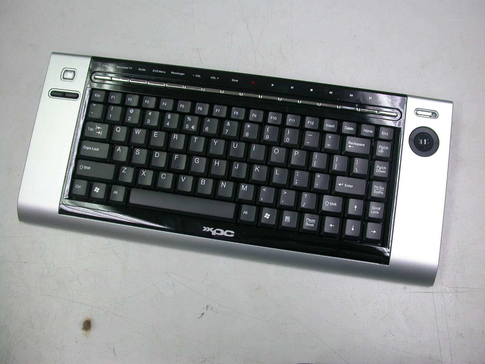
Click to zoom
Application Details
- Equipment Class
- DXX - Part 15 Low Power Communication Device Transmitter
- Date of Grant
- Sep 27, 2005
- Application Purpose
- Original Equipment
- Date of Application
- Sep 27, 2005
- Equipment Note
- Wireless Keyboard
- Frequency Range
- 27.14000000 - 27.14000000
- Company
- Shuttle Inc.
- Country
- Taiwan
Documents & Files
Document Text
Text extracted from the exhibit documents filed with the FCC. Open a document above to read the original.
Users Manual
Quick Installation Guide Hardware Installation (+ ) (-) 1. During initial installation of the USB device, the system will automatically detect a new hardware being added, and then bring up "Add New Hardware Wizard" dialogue box. Please follow the Wizard's USB driver installation steps. Once this installation step is completed the basic functions of the USB device will work under the operating system. 2. Make sure the batteries of the keyboard are installed correctly. Please follow the polarity signs in the battery compartment. Pairing Procedure The wireless kit can operate out of the box immediately. If it can’t work, please follow the steps below to process ID setting of the Wireless Kit. The ID-recognition function helps to protect against interference from other RF products in the same environment. Remember to pair ID when other RF products affect your keyboard kit. 1. Press the pairing/connect button on right-bottom of the PC. 2. Next, press and hold the pairing/connect button on the bottom of the keyboard at least 10 seconds. 3. Receiver LED indicator flashes 3 times rapidly as indication it’s paired with this keyboard. Note: - The whole procedure should be completed within 60 seconds. - Make sure your PC is on and running when doing the pairing procedure. - You don’t have to pair ID again after changing batteries. Battery Low Alarm - There are 4 different levels for battery power indication. The battery low icon will show in the Windows system tray when keyboard batteries are low (at Level 3 and Level 4). - The current status of battery power will show up on the Windows system tray when moving cursor on the KeyMaestro driver icon . - The battery low icon will disappear when you change the batteries. Battery Information 1. We recommend using alkaline batteries for a longer battery life. 2. Always change batteries when battery low alarm appears, otherwise the keyboard will shut down once the battery voltage is too low. 3. Don't mix different types of batteries or new and old batteries together. Always replace old batteries with new and same type batteries. 4. Remove batteries after long periods of non-use. Battery leakage or corrosion may damage the device quality and cause danger. Pairing/connect button on the bottom of the keyboard Receiver pairing/connect button on the PC ID Button FCC INFORMATION The Federal Communication Commission Radio Frequency Interference Statement includes the following paragraph: The equipment has been tested and found to comply with the limits for a Class B Digital Device, pursuant to part 15 of the FCC Rules. These limits are designed to provide reasonable protection against harmful interference in a residential installation. This equipment generates, uses and can radiate radio frequency energy and, if not installed and used in accordance with the instruction, may cause harmful interference to radio communication. However, there is no grantee that interference will not occur in a particular installation. If this equipment dose cause harmful interference to radio or television reception, which can be determined by turning the equipment off and on , the user is encouraged to try to correct the interference by one or more of the following measures: --Reorient or relocate the receiving antenna. --Increase the separation between the equipment and receiver. --Connect the equipment into an outlet on a circuit different from that to which the receiver is connected. --Consult the dealer or an experienced radio/TV technician for help. NOTE: The changes or modifications not expressly approved by the party responsible for compliance could void the user’s authority to operate the equipment. To comply with the FCC RF exposure compliance requirements, this device and its antenna must not be co-located or operating to conjunction with any other antenna or transmitter. English 9029URF Shuttle QIG 3100506820 Version 1.0 英文
External Photos
ETC Report No.: ET94S-08-207-02 Page A1 of A1 FCC ID.: S8C-KB10 ANNEX A: EXTERNAL CONSTRUCTION PHOTOS OF EUT 1. Outside view 1 of EUT 2. Outside view 2 of EUT
Internal Photos
ETC Report No.: ET94S-08-207-02 Page B1 of B3 FCC ID.: S8C-KB10 ANNEX B: INTERNAL CONSTRUCTION PHOTOS OF EUT 1. Inside View 1 of EUT 2. Inside View 2 of EUT ETC Report No.: ET94S-08-207-02 Page B2 of B3 FCC ID.: S8C-KB10 3. Inside View 3 of EUT 4. Front view of PCB1 ETC Report No.: ET94S-08-207-02 Page B3 of B3 FCC ID.: S8C-KB10 5. Rear view of PCB1 6. Front view of PCB2
Test Report
ETC Report No. : ET94S-08-207-02 Sheet 1 of 16 Sheets FCC ID.: S8C-KB10 Rev. No 1.0 CONFORMANCE TEST REPORT FOR FCC 47 CFR, Part 15 Subpart C Report No.: ET94S-08-207-02 Client: Shuttle Inc. Product: Wireless Keyboard Model: KB10 FCC ID: S8C-KB10 Manufacturer/supplier: GoodNice International Ltd. Date test item received: 2005/08/26 Date test campaign completed: 2005/09/09 Date of issue: 2005/09/22 The test result only corresponds to the tested sample. It is not permitted to copy this report, in part or in full, without the permission of the test laboratory. Total number of pages of this test report: 16 pages Total number of pages of photos: External photos 1 page Internal photos 3 pages Setup photos 2 pages Test Engineer Checked By Approved By Mark Mark Joe Hsieh ELECTRONICS TESTING CENTER, TAIWAN NO.8, LANE 29, WENMING RD., LESHAN TSUEN, GUISHAN SHIANG, TAOYUAN COUNTY, TAIWAN 33383, R.O.C. TEL: (03) 3276170~4 INT: +886-3-3276170~4 FAX: (03) 3276188 INT: +886-3-3276188 ETC Report No. : ET94S-08-207-02 Sheet 2 of 16 Sheets FCC ID.: S8C-KB10 Rev. No 1.0 Client : Shuttle Inc. Address : No. 30, Lane 76, Rei Kuang Rd., Nei-Hu Dist., Taipei, Taiwan Manufacturer : GoodNice International Ltd. Address : Fushi Industrial zone, Qinghu Industrial Park, QingXi Town, Dong Guan, Guang Dong, China. EUT : Wireless Keyboard Trade name : Shuttle Model No. : KB10 Power Source : DC 1.5V*4 Regulations applied : FCC 47 CFR, Part 15 Subpart C (2005) The testing described in this report has been carried out to the best of our knowledge and ability, and our responsibility is limited to the exercise of reasonable care. This certification is not intended to believe the sellers from their legal and/or contractual obligations. The compliance test is only certified for the test equipment and the results of the testing report relate only to the item tested. The compliance test of this report was conducted in accordance with the appropriate standards. It’s not intention to assure the quality and performance of the product. This report shall not be reproduced except in full, without the approval of ETC. This report must not be used by the client to claim product endorsement by NVLAP or any agency of the U.S. Government. Laboratory Introduction: Electronics Testing Center, Taiwan is recognized, filed and mutual recognition arrangement as following: 1 ISO9001: TüV Product Service 2 ISO/IEC 17025: BSMI, CNLA, DGT, NVLAP, CCIBLAC, UL, Compliance 3 Filing: FCC, Industry Canada, VCCI 4 MRA: Australia, Hong Kong, New Zealand, Singapore, USA, Japan, Korea, China, APLAC through CNLA 5 FCC Registration Number: 90588, 91094, 91095 NVLAP Lab Code 200133-0 ETC Report No. : ET94S-08-207-02 Sheet 3 of 16 Sheets FCC ID.: S8C-KB10 Rev. No 1.0 Table of Contents Page 1. GENERAL INFORMATION ......................................................................................................................................4 1.1 P RODUCT D ESCRIPTION .................................................................................................................................................4 1.2 C HARACTERISTICS OF D EVICE : ......................................................................................................................................4 1.3 T EST M ETHODOLOGY ....................................................................................................................................................4 1.4 T EST F ACILITY ...............................................................................................................................................................4 2. TEST SYSTEM AND LIMITATION .........................................................................................................................5 2.1 D EVICE FOR T ESTED S YSTEM ........................................................................................................................................5 2.2 RESTRICTED BANDS OF OPERATION...............................................................................................................................5 2.3 LIMITATION....................................................................................................................................................................6 2.4 L ABELING R EQUIREMENT ..............................................................................................................................................7 2.5 U SER I NFORMATION .......................................................................................................................................................7 3. RADIATED EMISSION MEASUREMENT..............................................................................................................8 3.1 A PPLICABLE S TANDARD .................................................................................................................................................8 3.2 M EASUREMENT P ROCEDURE .........................................................................................................................................9 3.3 T EST D ATA ..................................................................................................................................................................11 3.4 CALCULATION..............................................................................................................................................................14 3.5 RADIATED TEST EQUIPMENT.......................................................................................................................................14 3.6 M EASURING I NSTRUMENT S ETUP .................................................................................................................................15 4. CONDUCTED EMISSION MEASUREMENT ........................................................................................................16 ETC Report No. : ET94S-08-207-02 Sheet 4 of 16 Sheets …
Text truncated - open the document above for the full version.
Test Setup Photos
ETC Report No. : ET94S-08-207-02 Sheet 1 of 2 Sheets FCC ID.: S8C-KB10 Photos of Radiation Measuring Setup ETC Report No. : ET94S-08-207-02 Sheet 2 of 2 Sheets FCC ID.: S8C-KB10
Contact Information
Applicant
Weber Liu(Manager)
Test Firm
Electronics Testing Center, TaiwanWin-Po Tsai
Technical Specifications
| # | Rule Parts | Frequency Range | Power Output |
|---|---|---|---|
| 1 | 15C | 27.14 MHz - 27.14 MHz | - |
Other Applications from Shuttle Inc.
S8CNS02V2
Mar 10, 2021XPC nano
Equipment Class
DSS - Part 15 Spread Spectrum Transmitter
S8C-DSA2LS
May 19, 2014Embedded computer
Equipment Class
DTS - Digital Transmission System
S8C-PN20
Oct 15, 200711g module
Equipment Class
DTS - Digital Transmission System