S9GH500H500 Access Point
Ruckus Wireless, Inc.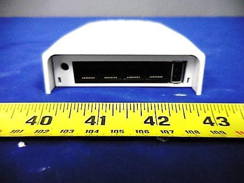
Click to zoom
Application Details
- Equipment Class
- DTS - Digital Transmission System
- Date of Grant
- Feb 08, 2015
- Application Purpose
- Original Equipment
- Date of Application
- Feb 08, 2015
- Equipment Note
- H500 Access Point
- Frequency Range
- 2412.00000000 - 2462.00000000
- Company
- Ruckus Wireless, Inc.
- Country
- United States
Documents & Files
Document Text
Text extracted from the exhibit documents filed with the FCC. Open a document above to read the original.
Users Manual
Copyright © 2014 Ruckus Wireless, Inc. Page 1 of 4 Draft Published 11 December 2014, Part Number 800-70718-001 Rev A H500 Access Point Quick Setup Guide This Quick Setup Guide provides step-by-step instructions on how to set up your Ruckus Wireless H500 Dual Band 802.11ac Multimedia Wi-Fi Access Point Wall Switch. After completing the steps described in this Guide, yo u will be able to access the Wi-Fi Wall Switch and begin providing wired and wireless network access to users. The rest of this document refers to the H500 Access Point Wall Switch as the H500 . The H500 has many options: • It can be mounted on a standard USA- or EU-style single-gang wall outlet box. • It can be powered by a cust omer-supplied IEEE 802.3af/at- compliant PoE switch or inject or, or can be powered by an optional customer-ordered DC power adapter. • It has side cutouts for one or two Ethernet bypass cables. The mounting bracket has locating hooks to keep the bypass cables aligned with the cutout s when attachin g the H500 to the mounting base. • It can have a low-power (0.5W or less) customer-supplied USB adapter plugged in. The USB adapter is very difficult to remove after the H500 is attached to the mounting base. A BOUT P OWERING P ERIPHERAL D EVICES The H500 can supply power to USB and PoE-powered devices, and the power supplied depends on the PoE power supplied to the H500.• The USB port is intended for low-power devices such as BLE beacons. The maximum power th at the USB port can supply is 0.5W. • The PoE port is intended for PoE-powered peripheral devices such as IP telephones. T HIS G UIDE IN O THER L ANGUAGES • 请从以下网站获得该指南的简体中文版 https://support.ruc kuswireless.com . • Vous trouverez la version française de ce guide à l'adresse suivante https://support.r uckuswireless.com . • このガイドの日本語版は https://support.ruckuswireless.com でご覧ください。 • 이 가이드의 한국어 버전은 웹 사이트 ( https://support.r uckuswireless.com ) 에서 확인하시기 바랍니 다 . • Veja a versão em português (Brasil) deste guia em https://support.ruc kuswireless.com. • Puede ver la versión en español (América Latina) de esta guía en https://support.ruc kuswireless.com. B EFORE Y OU B EGIN Before deploying Ruckus Wireless products, please check for the latest software and the release documentation.• User Guides and Release Notes are available at http://support.ruckusw ireless.com/documents . • Software Upgrades are available athttp://support.ruckusw ireless.com/software . • Open Source information is available athttp://opensource.ruckuswireless.com . • Software License and Limite d Warranty are available at http://support.ruckusw ireless.com/warranty . P ACKAGE C ONTENTS • H500 Access Point Wall Switch • Mounting bracket • Two 10mm M3x0.5 thread Torx flat head machine screws • Two 1” 6-32 thread Phillips pan head machine screws • Product warranty statement • Registration card • Regulatory flyer • Declaration of Conformity, if required •This Quick Setup Guide Note: The H500 requires Ruckus Wireless base image 100.0.1 firmware or later. Managed H500 deployments require RuckOS for SmartCell Gateway (SCG) 3.1 or later, RuckOS for virtual SmartCell Gateway (vSCG) 3.0 or later, or ZoneFlex (ZF) 9.10 or later. H500 Power Options and Available Power Out for PoE Out and USB H500 Power Source Power Available for PoE Out and USB 802.3af PoE 5W total 802.3at PoE 12.95W PoE Out (802.3af Class 3) and 0.5W USB DC power adapter (sold separately) 12.95W PoE Out (802.3af Class 3) and 0.5W USB Copyright © 2014 Ruckus Wireless, Inc. Page 2 of 4 Draft Published 11 December 2014, Part Number 800-70718-001 Rev A S TEP 1: C OLLECT T OOLS AND S ETUP R EQUIREMENTS • No. 2 Phillips screwdriver and T 10 Torx driver for the mounting bracket screws • A standard USA- or EU-style single-gang wall outlet box • One of the following:• Customer-supplied IEEE 802.3a f/at-compliant PoE switch and customer-supplied Ethernet cable • Customer-supplied IEEE 802.3af/at-compliant PoE injector and customer-s upplied Ethernet cable • Customer-ordered DC power adapter (Ruckus part number 902-0170-XX10, sold separately) • An Ethernet cable with or wi thout PoE run through the wall from your LAN through the wall outlet box • (optional) One or two separate Ethernet bypass cables run through the outlet box • A computer with an Ethernet port and a wireless card • One Cat 5e or better Ethernet cable S TEP 2: C ONNECT THE C OMPUTER TO THE H500 Figure 1: Top view1 After removing your H500 from its package, place it next to your computer. 2 Using an Ethernet cable, connect your computer’s network port to the PoE In port on the back of the H500. 3 Using an AC adapter (sold separately), connect the H500 12VDC port to a protected power source. Alternatively, connect the PoE port to a PoE injector or switch for both power and network connections. 4 Verify that the Power LED on th e external enclosure is a steady green. Figure 2: Back view S TEP 3: P REPARE Y OUR C OMPUTER FOR H500 S ETUP 1 On your Windows 7 computer, configure your network adapter from the Local Area Connection settings as follows: • Start > Control Panel > Network and Sharing Center > Change Adapter Settings 2 Edit the TCP/IPv4 addre ss settings as follows: • Local Area Connection > Properties > Internet Protocol Version 4 (TCP/IPv4) > Properties The TCP/IPv4 Properties dialog box appears. 3 Select Use the following IP address (if it is not already selected) and then make the following entries: • IP address : 192.168.0.22 (or any address in the 192.168.0.x network, except 192.168.0.1) • Subnet mask : 255.255.255.0 • Default gateway : 192.168.0.1 Leave the DNS server fields empty. 4 Click OK to save your changes. Your changes are put into effect immediately. PoE In Port12VDC Port Note: The following procedures assume Windows 7 as the operating system. Procedures for other OS’s are similar. Important! Write down all of the currently active settings so you can restore your computer to its current configuration later (when this process is complete). Copyright © 2014 R…
Text truncated - open the document above for the full version.
Users Manual
Page 1 Federal Communications Commission Notices This product complies with Part 15 of the FCC Rules. Operation is subject to the following two conditions: (1) this device may not cause harmful interference, and (2) this device must accept any interference received, including interference that may cause undesired operation. Caution: Changes or modifications to this equipment that have not been approved by Ruckus Wireless may void the user's authority to operate this equipment. Note: This equipment has been tested and found to comply with the limits for a Class B digital device, pursuant to part 15 of the FCC Rules. These limits are designed to provide reasonable protection against harmful interference in a residential installation. This equipment generates, uses and can radiate radio frequency energy and, if not installed and used in accordance with the instructions, may cause harmful interference to radio communications. However, there is no guarantee that interference will not occur in a particular installation. If this equipment does cause harmful interference to radio or television reception, which can be determined by turning the equipment off and on, the user is encouraged to try to correct the interference by one or more of the following measures: —Reorient or relocate the receiving antenna. —Increase the separation between the equipment and receiver. —Connect the equipment into an outlet on a circuit different from that to which the receiver is connected. —Consult the dealer or an experienced radio/TV technician for help. Industry Canada Statement Under Industry Canada regulations, this radio transmitter may only operate using an antenna of a type and maximum (or lesser) gain approved for the transmitter by Industry Canada. To reduce potential radio interference to other users, the antenna type and its gain should be so chosen that the equivalent isotropically radiated power (e.i.r.p.) is not more than that necessary for successful communication. Conformément à la réglementation d'Industrie Canada, le présent émetteur radio peut fonctionner avec une antenne d'un type et d'un gain maximal (ou inférieur) approuvé pour l'émetteur par Industrie Canada. Dans le but de réduire les risques de brouillage radioélectrique à l'intention des autres utilisateurs, il faut choisir le type d'antenne et son gain de sorte que la puissance isotrope rayonnée équivalente (p.i.r.e.) ne dépasse pas l'intensité nécessaire à l'établissement d'une communication satisfaisante. This device complies with Industry Canada licence-exempt RSS standard(s). Operation is subject to the following two conditions: (1) this device may not cause interference, and (2) this device must accept any interference, including interference that may cause undesired operation of the device. Le présent appareil est conforme aux CNR d'Industrie Canada applicables aux appareils radio exempts de licence. L'exploitation est autorisée aux deux conditions suivantes : (1) l'appareil ne doit pas produire de brouillage, et (2) l'utilisateur de l'appareil doit accepter tout brouillage radioélectrique subi, même si le brouillage est susceptible d'en compromettre le fonctionnement. The device for operation in the band 5150-5250 MHz is only for indoor use to reduce the potential for harmful interference to co-channel mobile satellite systems; the maximum antenna gain permitted for devices in the bands 5250-5350 MHz and 5470-5725 MHz shall comply with the e.i.r.p. limit; and the maximum antenna gain permitted for devices in the band 5725-5825 MHz shall comply with the e.i.r.p. limits specified for point-to-point and non point-to-point operation as appropriate. Le dispositif de fonctionnement dans la bande 5150-5250 MHz est réservé à une utilisation en intérieur pour réduire le risque d'interférences nuisibles à la co-canal systèmes mobiles par satellite, le gain d'antenne maximal autorisé pour les appareils dans les bandes 5250-5350 MHz et 5470-5725 MHz doit se conformer à la pire limite, et le gain d'antenne maximal autorisé pour les appareils dans la bande 5725-5825 MHz doivent être conformes avec le pire limites spécifiées à point-à-ponctuelles et non point-à-point de fonctionnement selon qu'il convient. Operation in the 5600-5650 MHz band is not allowed in Canada. High-power radars are allocated as primary users (i.e. priority users) of the bands 5250-5350 MHz and 5650-5850 MHz and that these radars could cause interference and/or damage to LE-LAN devices. Opération dans la bande 5600-5650 MHz n'est pas autorisée au Canada. Haute puissance radars sont désignés comme utilisateurs principaux (c.-à- utilisateurs prioritaires) des bandes 5250-5350 MHz et 5650-5850 MHz et que ces radars pourraient causer des interférences et / ou des dommages à dispositifs LAN-EL. Radiation Exposure Statement The device has been found to be compliant to the requirements set forth in CFR 47 Sections 2.1091 and Industry Canada RSS-102 for an uncontrolled environment. The antenna(s) used for this transmitter must be installed to provide a separation distance of at least 20 cm from all persons and must not be co-located or operating in conjunction with any other antenna or transmitter. Le dispositif a été jugé conforme aux exigences énoncées dans les articles 47 CFR 2.1091 et Industrie Canada RSS-102 pour un environnement non contrôlé. L'antenne (s) utilisée pour ce transmetteur doit être installé pour fournir une distance de séparation d'au moins 20 cm de toutes les personnes et ne doit pas être co-localisés ou fonctionner en conjonction avec une autre antenne ou transmetteur. Mexico Statement “La operación de este equipo está sujeta a las siguientes dos condiciones: (1) es posible que este equipo o dispositivo no cause interferencia perjudicial y (2) este equipo o dispositivo debe aceptar cualquier interferencia, incluyendo la que pueda causar su operación no deseada.” Page 2 Professionally Installed Products The product is to be installed according to the installa…
Text truncated - open the document above for the full version.
Attestation Statements
1/13/2015 To: Federal Communications Commission Authorization and Evaluation Division 7435 Oakland Mills Road Columbia, MD Subject: DFS Channels for FCC ID: S9GH500 Ruckus Wireless, Inc. hereby declares that the device FCC IS: S9GH500 will not operate outside the bands of approval. Operation on DFS bands is disabled for initial DTS and NII approval. A Class Two Permissive Change (CLIIPC) will be pursued to gain approval in the DFS bands. Operation on DFS bands will remain disabled until approved by the FCC. Sincerely, Clinton Bradley / Compliance Engineer 350 West Java Drive, Sunnyvale, CA 94089 [email protected] / 408-636-4368
Attestation Statements
2/6/2015 To: Federal Communications Commission Authorization and Evaluation Division 7435 Oakland Mills Road Columbia, MD Subject: Professional Installation for FCC ID: S9GH500 Ruckus Wireless, Inc. hereby declares that the device FCC ID: S9GH500 will only be installed by a professional installer. The product is only sold through Authorized Partners. The H500 is not for sale to the general public. Professional installation is guaranteed based on the use of only Authorized Partners and distribution channels. Professional training and support is provided as part of the Authorized Partner programs. Sincerely, Clinton Bradley / Compliance Engineer 350 West Java Drive, Sunnyvale, CA 94089 [email protected] / 408-636-4368
Cover Letter(s)
775 Montague Expressway Milpitas, CA 95035 Tel: 408-526-1188 Fax: 408-526-1088 Email: [email protected] Project and Product Certification Representative Authorization Letter Reason for Amendment (current / obsolete) Revision History Approved Date From To Initial Release (obsolete) 1.0 1.0 Nov-14-2006 Revised wording (obsolete) 1.0 2.0 Sept–25-2007 Updated company template (obsolete) 2.0 3.0 Jan-31-2012 Updated letter information (obsolete) 3.0 4.0 May-23-2014 Added FCC ID field (current) 4.0 5.0 Sept 16 2014 SCS-F18: Project and Product Certification Representative Authorization Letter Page 2 of 2 Rev 5.0 01/09/2015 To: SIEMIC, Inc. 775 Montague Expressway, Milpitas, CA 95035 USA Dear Sir/Madam, Re: Project and Product Certification Representative Authorization Letter We, Ruckus Wireless, Inc., hereby authorize SIEMIC, Inc. to act as Certification Body for certifying for the following project(s): FCC ID: S9GH500 Product Description: H500 Access Point Model: H500 We affirm that between SIEMIC, Inc. and Ruckus Wireless, Inc., any difference in understanding, including test plan, measurement methods, applicable standards and relevant procedures and processes have been resolved prior to commencement of testing activities. Sincerely, Clinton Bradley / Compliance Engineer 350 West Java Drive, Sunnyvale, CA 94089 [email protected] / 408-636-4368
Cover Letter(s)
775 Montague Expressway Milpitas, CA 95035 Tel: 408-526-1188 Fax: 408-526-1088 Email: [email protected] Confidentiality Request Letter Reason for Amendment (current / obsolete) Revision History Approved Date From To Initial Release (obsolete) 1.0 1.0 Nov-14-2006 Adding CFR 2.459 (obsolete) 1.0 2.0 August – 11 - 2008 Updated company template & Added text box (current) 2.0 3.0 Jan-31-2012 SCS-F19: Confidentiality Request Letter Page 2 of 2 Rev 3.0 01/13/2015 To: Federal Communications Commission Authorization and Evaluation Division 7435 Oakland Mills Road Columbia, MD Subject: Permanent Confidentiality Request for FCC ID: S9GH500 We hereby request confidential treatment of information accompanying this application as outlined below: - Block Diagram - Schematics - Operational Description The above materials contain trade secrets and proprietary information not customarily released to the public. The public disclosure of these materials may be harmful to the applicant and provide unjustified benefits to its competitors. The applicant understands that pursuant to Section 0.457 & 0.459 of the Rules, disclosure of this application and all accompanying documentation will not be made before the date of the Grant for this application. Sincerely, Clinton Bradley / Compliance Engineer 350 West Java Drive, Sunnyvale, CA 94089 [email protected] / 408-636-4368
External Photos
Test report No. Ext-Pic_SL14091001-RUC-015 Page 1 of 1 775 Montague Expressway, Milpitas, CA 95035, USA • Phone: (+1) 408 526 1188 • Facsimile (+1) 408 526 1088 Visit us at: www.siemic.com; Follow us at: EUT Photos – External Top View Bottom View Front View Rear View Left Side View Right Side View
ID Label/Location Info
Label & Location
Internal Photos
Test report No. Int-Pic_SL14091001-RUC-015 Rev1.0 Page 1 of 1 775 Montague Expressway, Milpitas, CA 95035, USA • Phone: (+1) 408 526 1188 • Facsimile (+1) 408 526 1088 Visit us at: www.siemic.com; Follow us at: EUT Photos - Internal Main Board with Shielding Top View Main Board without Shielding Top View Main Board without Shielding Close View Main Board Bottom View Antenna Location
RF Exposure Info
MPE CALCULATION FCC ID: S9GH500 RF Exposure Requirements: 47 CFR §1.1307(b) RF Radiation Exposure Limits: 47 CFR §1.1310 RF Radiation Exposure Guidelines: FCC OST/OET Bulletin Number 65 EUT Frequency Band: 2412 - 2462 MHz; 5180 – 5240 MHz, 5745 - 5825MHz Limits for General Population/Uncontrolled Exposure in the band of: 1500 - 100,000 MHz Power Density Limit: 1 mW / cm 2 Equation: S = PG / 4R 2 or R = √PG / 4S Where, S = Power Density P = Power Input to Antenna G = Antenna Gain R = distance to the center of radiated antenna ______________________________________________________________________________________________________________________ Prediction distance 20cm EUT: H500 (UNII Band): Power = 25.81dBm, Antenna Gain = 1 dBi, Power density = 0.09544 mW/ cm 2 (2.4GHz Band): Power = 20.41dBm, Antenna Gain = 0 dBi, Power density = 0.021864 mW/ cm 2 Total Ratio= (P 2.4GHz /1) + (P 5GHzUNII /1) = 0.021864 mW/ cm 2 + 0.09544 mW/ cm 2 = 0.117304 mW/ cm 2 The Above Result had shown that the Device complied with MPE requirement. Completed By: Angel Escamilla SIEMIC, Inc. 775 Montague Expressway, Milpitas, CA 95035 Date: January 26, 2015
Test Report
775 Montague Expressway, Milpitas, CA 95035, USA • Phone: (+1) 408 526 1188 • Facsimile (+1) 408 526 1088 Visit us at: www.siemic.com; Follow us at: Report No.: FCC_RF_SL14091001-RUC-015_DTS Rev1.0 Supersede Report No.: FCC_RF_SL14091001-RUC-015_DTS Applicant : Ruckus Wireless, Inc. Product Name : Access Point Model No. : H500 Test Standard : 47 CFR 15.247 Test Method : ANSI C63.4: 2014 558074 D01 DTS Meas Guidance v03r02 FCC ID : S9GH500 IC ID : 5912A-H500 Dates of test : 11/08/ 2014 – 12/10/2014 Issue Date : 02/06/2015 Test Result : ☒ Pass ☐ Fail Equipment complied with the specification [X] Equipment did not comply with the specification [ ] This Test Report is Issued Under the Authority of: Angel Escamilla David Zhang Test Engineer Engineer Reviewer This test report may be reproduced in full only Test result presented in this test report is applicable to the tested sample only Issued By: SIEMIC Laboratories 775 Montague Expressway, Milpitas, 95035 CA RF TEST REPORT Test report No. FCC_RF_SL14091001-RUC-015_DTS Rev1.0 Page 2 of 56 775 Montague Expressway, Milpitas, CA 95035, USA • Phone: (+1) 408 526 1188 • Facsimile (+1) 408 526 1088 Visit us at: www.siemic.com; Follow us at: Laboratory Introduction SIEMIC, headquartered in the heart of Silicon Valley, with superior facilities in US and Asia, is one of the leading independent testing and certification facilities providing customers with one-stop shop services for Compliance Testing and Global Certifications. In addition to testing and certification, SIEMIC provides initial design reviews and compliance management throughout a project. Our extensive experience with China, Asia Pacific, North America, European, and International compliance requirements, assures the fastest, most cost effective way to attain regulatory compliance for the global markets. Accreditations for Conformity Assessment Country/Region Accreditation Body Scope USA FCC, A2LA EMC, RF/Wireless, Telecom Canada IC, A2LA, NIST EMC, RF/Wireless, Telecom Taiwan BSMI, NCC, NIST EMC, RF, Telecom, Safety Hong Kong OFTA, NIST RF/Wireless, Telecom Australia NATA, NIST EMC, RF, Telecom, Safety Korea KCC/RRA, NIST EMI, EMS, RF, Telecom, Safety Japan VCCI, JATE, TELEC, RFT EMI, RF/Wireless, Telecom Mexico NOM, COFETEL, Caniety Safety, EMC, RF/Wireless, Telecom Europe A2LA, NIST EMC, RF, Telecom, Safety Israel MOC, NIST EMC, RF, Telecom, Safety Accreditations for Product Certifications Country Accreditation Body Scope USA FCC TCB, NIST EMC, RF, Telecom Canada IC FCB, NIST EMC, RF, Telecom Singapore iDA, NIST EMC, RF, Telecom EU NB EMC & R&TTE Directive Japan MIC (RCB 208) RF, Telecom Hong Kong OFTA (US002) RF, Telecom Test report No. FCC_RF_SL14091001-RUC-015_DTS Rev1.0 Page 3 of 56 775 Montague Expressway, Milpitas, CA 95035, USA • Phone: (+1) 408 526 1188 • Facsimile (+1) 408 526 1088 Visit us at: www.siemic.com; Follow us at: CONTENTS 1 REPORT REVISION HISTORY ....................................................................................................................................... 4 2 EXECUTIVE SUMMARY ................................................................................................................................................. 5 3 CUSTOMER INFORMATION .......................................................................................................................................... 5 4 TEST SITE INFORMATION ............................................................................................................................................ 5 5 MODIFICATION ............................................................................................................................................................. 5 6 EUT INFORMATION ...................................................................................................................................................... 6 6.1 EUT Description ........................................................................................................................................................ 6 6.2 Radio Description ...................................................................................................................................................... 6 6.3 EUT Photos - External ............................................................................................................................................... 8 6.4 EUT Photos - Internal ................................................................................................................................................ 9 6.5 EUT Test Setup Photos ........................................................................................................................................... 10 7 SUPPORTING EQUIPMENT/SOFTWARE AND CABLING DESCRIPTION ....................................................................... 12 7.1 Supporting Equipment ............................................................................................................................................. 12 7.2 Cabling Description ................................................................................................................................................. 12 7.3 Test Software Description ........................................................................................................................................ 12 8 TEST SUMMARY ......................................................................................................................................................... 13 9 MEASUREMENT UNCERTAINTY ................................................................................................................................. 14 10 MEASUREMENTS, EXAMINATION AND DERIVED RESULTS .................................................................................. 15 10.1 Conducted Emissions ...............................................................................................…
Text truncated - open the document above for the full version.
Test Setup Photos
Test report No. Setup-Pic_SL14091001-RUC-015 Page 1 of 2 775 Montague Expressway, Milpitas, CA 95035, USA • Phone: (+1) 408 526 1188 • Facsimile (+1) 408 526 1088 Visit us at: www.siemic.com; Follow us at: Test Setup Photos AC Line Conducted Emissions – Front View AC Line Conducted Emissions – Rear View Radiated Emissions (<1GHz) – Front View Radiated Emissions (<1GHz) – Rear View Radiated Emissions (>1GHz) – Front View Radiated Emissions (>1GHz) – Rear View Test report No. Setup-pic_SL14091001-RUC-015 Page 2 of 2 775 Montague Expressway, Milpitas, CA 95035, USA • Phone: (+1) 408 526 1188 • Facsimile (+1) 408 526 1088 Visit us at: www.siemic.com; Follow us at: Radiated Emissions (>18GHz) – Front View Radiated Emissions (>18GHz) – Rear View
Contact Information
Applicant
Ivaylo Tankov(Principal Wireless Compliance Engineering)
Test Firm
SIEMIC LabsLeslie BAI
[email protected]4085261188
Technical Specifications
| # | Rule Parts | Frequency Range | Power Output |
|---|---|---|---|
| 1 | 15C | 2.41 GHz - 2.46 GHz | 110.00 mW |
Other Applications from Ruckus Wireless, Inc.
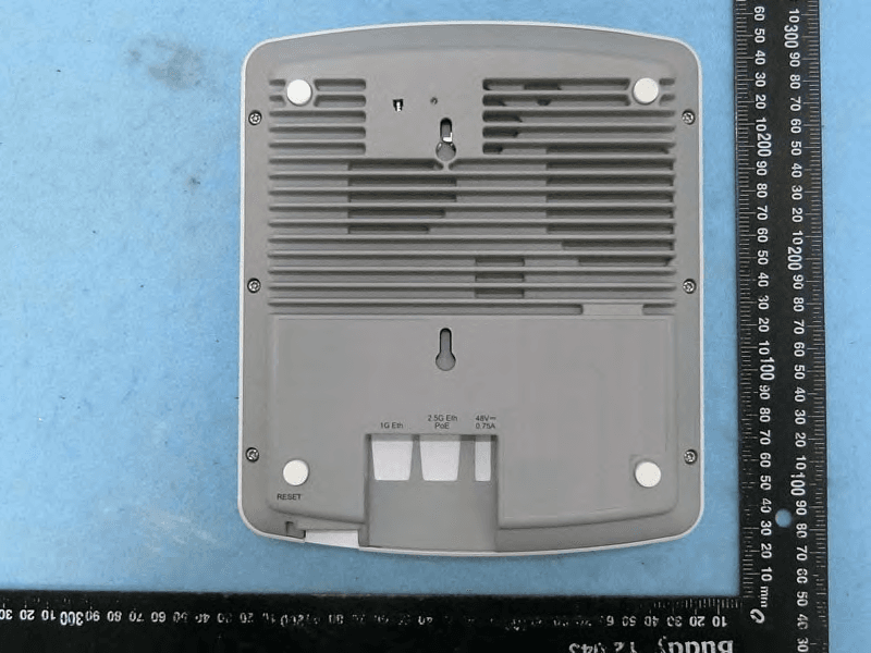
S9GR650P
Jul 11, 2021R650p Access Point
Equipment Class
DTS - Digital Transmission System
S9GR350
Jun 30, 2021Access Point
Equipment Class
NII - Unlicensed National Information Infrastructure TX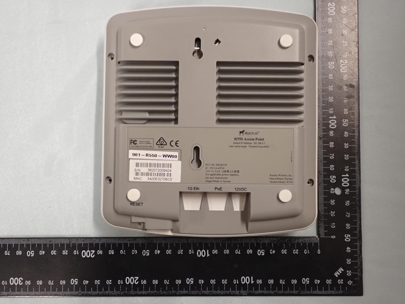
S9GR550P
Jun 30, 2021Wireless Access Point
Equipment Class
DTS - Digital Transmission System
S9GT350C
Mar 23, 2021Access point
Equipment Class
NII - Unlicensed National Information Infrastructure TX
S9GT350D
Mar 10, 2021Access point
Equipment Class
DTS - Digital Transmission System