S9GMF2900Media Access Point, 802.11b/g
Ruckus Wireless, Inc.
Click to zoom
Application Details
- Equipment Class
- DTS - Digital Transmission System
- Date of Grant
- Jun 13, 2005
- Application Purpose
- Original Equipment
- Date of Application
- Jun 13, 2005
- Equipment Note
- Media Access Point, 802.11b/g
- Frequency Range
- 2412.00000000 - 2462.00000000
- Company
- Ruckus Wireless, Inc.
- Country
- United States
Documents & Files
Document Text
Text extracted from the exhibit documents filed with the FCC. Open a document above to read the original.
Users Manual
MediaFlex 2900 Multimedia Access Point User’s Guide Part number: 8000001 May, 2005 2MediaFlex 2900 Multimedia Access Point User’s Guide8000001, May, 2005 Copyright © 2005 Video54, Inc. All rights reserved. May, 2005. Trademarks Video54, BeamFlex™, MediaFlex™, MediaFlex 2900 Multimedia Access Point, MediaFlex 2501 Multimedia Wireless Adapter , M2900 AP, and M2501 Adapter are trademarks of Video54, Inc. All other brand and product names are registered trademarks of their respective holders. Statement of Conditions In the interest of improving internal design, operational function, and/or reliability, Video54, Inc. reserves the right to make changes to the products described in this document without notice. Video54, Inc. does not assume any liability that may occur due to the use or application of the product(s) or circuit layout(s) described herein. Federal Communications Commission (FCC) Compliance Notice: Radio Frequency Notice The device has met the FCC 15.247 requirement. In order to comply with the FCC RF exposure requirement, the user must keep 20cm away from the antenna. This device has been tested and found to comply with the limits for a Class B digital device, pursuant to part 15 of the FCC Rules. These limits are designed to provide reasonable protection against harmful interference in a residential installation. This device generates, uses, and can radiate radio frequency energy and, if not installed and used in accordance with the instructions, may cause harmful interference to radio communications. However, there is no guarantee that interference will not occur in a particular installation. If this device does cause harmful interference to radio or television reception, which can be determined by turning the equipment off and on, the user is encouraged to try to correct the interference by one or more of the following measures: •Reorient or relocate the receiving antenna. •Increase the separation between the equipment and receiver. •Connect the equipment into an outlet on a circuit different from that to which the receiver is connected. •Consult the dealer or an experienced radio/TV technician for help. Changes or modifications not expressly approved by the party responsible for compliance could void the user's authority to operate the equipment. EN 55 022 Declaration of Conformance This is to certify that the MediaFlex 2900 Multimedia Access Point is shielded against the generation of radio interference in accordance with the application of Council Directive 89/336/EEC, Article 4a. Conformity is declared by the application of EN 55 022 Class B (CISPR 22). 8000001, May, 2005MediaFlex 2900 Multimedia Access Point User’s Guide3 Contents Preface . . . . . . . . . . . . . . . . . . . . . . . . . . . . . . . . . . . . . . . . . . . . . . . . . . . . . . . . . . . . . 5 Who Should Use this Guide . . . . . . . . . . . . . . . . . . . . . . . . . . . . . . . . . . . . . . . . . . . . . . . . . . . . . . . .5 What You’ll Find in this Guide . . . . . . . . . . . . . . . . . . . . . . . . . . . . . . . . . . . . . . . . . . . . . . . . . . . . .5 Typographic conventions . . . . . . . . . . . . . . . . . . . . . . . . . . . . . . . . . . . . . . . . . . . . . . . . . . . . . . . . . .5 System Requirements . . . . . . . . . . . . . . . . . . . . . . . . . . . . . . . . . . . . . . . . . . . . . . . . . . . . . . . . . . . . .6 Support and Warranty Information. . . . . . . . . . . . . . . . . . . . . . . . . . . . . . . . . . . . . . . . . . . . . . . . . . .6 Chapter 1: Introduction . . . . . . . . . . . . . . . . . . . . . . . . . . . . . . . . . . . . . . . . . . . . .7 MediaFlex™ . . . . . . . . . . . . . . . . . . . . . . . . . . . . . . . . . . . . . . . . . . . . . . . . . . . . . . . . . . . . . . . . . . . .8 BeamFlex™ . . . . . . . . . . . . . . . . . . . . . . . . . . . . . . . . . . . . . . . . . . . . . . . . . . . . . . . . . . . . . . . . . . . .8 Key Features . . . . . . . . . . . . . . . . . . . . . . . . . . . . . . . . . . . . . . . . . . . . . . . . . . . . . . . . . . . . . . . . . . . .8 Chapter 2: Installation and Setup. . . . . . . . . . . . . . . . . . . . . . . . . . . . . . . . . . . . .11 Packing List . . . . . . . . . . . . . . . . . . . . . . . . . . . . . . . . . . . . . . . . . . . . . . . . . . . . . . . . . . . . . . . . . . . .12 MediaFlex 2900 Multimedia Access Point. . . . . . . . . . . . . . . . . . . . . . . . . . . . . . . . . . . . . . . . . . . . .12 Front View . . . . . . . . . . . . . . . . . . . . . . . . . . . . . . . . . . . . . . . . . . . . . . . . . . . . . . . . . . . . . . . . . .12 LED Status Lights. . . . . . . . . . . . . . . . . . . . . . . . . . . . . . . . . . . . . . . . . . . . . . . . . . . . . . . . . . . . . . . .13 Rear View. . . . . . . . . . . . . . . . . . . . . . . . . . . . . . . . . . . . . . . . . . . . . . . . . . . . . . . . . . . . . . . . . . .14 Placement Guidelines . . . . . . . . . . . . . . . . . . . . . . . . . . . . . . . . . . . . . . . . . . . . . . . . . . . . . . . . . . . . .15 Establishing a good general location . . . . . . . . . . . . . . . . . . . . . . . . . . . . . . . . . . . . . . . . . . . . . .15 Using the Air Quality Indicator to fine-tune the placement. . . . . . . . . . . . . . . . . . . . . . . . . . . . .15 Connecting to the M2900 AP . . . . . . . . . . . . . . . . . . . . . . . . . . . . . . . . . . . . . . . . . . . . . . . . . . . . . . .16 Manually Configuring an IP Address on Your PC . . . . . . . . . . . . . . . . . . . . . . . . . . . . . . . . . . .16 Connecting a PC to the M2900 AP . . . . . . . . . . . . . . . . . . . . . . . . . . . . . . . . . . . . . . . . . . . . . . .17 Accessing the Web Interface . . . . . . . . . . . . . . . . . . . . . . . . . . . . . . . . . . . . . . . . . . . . . . . . . . . . . . .18 Chapter 3: Using the Video54 Web Interface . . . . . . . . . . . . . . . . . . . . . . . . . . .19 Wireless Settings Worksheet . . . . . . . . . . . . . . . . . . . . . . …
Text truncated - open the document above for the full version.
Cover Letter(s)
Federal Communications Commission Authorization and Evaluation Division Confidentiality Request regarding application for certification of FCC ID: S9GMF2900 Pursuant to Sections 0.457 and 0.459 of the Commission’s Rules, we hereby request confidential treatment of information accompanying this application as outlined below: Schematics Part List Block Diagram The above materials contain trade secrets and proprietary information not customarily released to the public. The public disclosure of these materials may be harmful to the applicant and provide unjustified benefits to its competitors. The applicant understands that pursuant to Section 0.457 of the Rules, disclosure of this application and all accompanying documentation will not be made before the date of the Grant for this application. Sincerely, Michael Lin Director of Engineering Video54 Technologies, Inc. 5/19/2005
External Photos
EXHIBIT C - EUT EXTERNAL PHOTOGRAPHS EUT – Front View EUT – Rear View Power Supply – Top View Power Supply – Rear View
ID Label/Location Info
EXHIBIT A - FCC ID LABEL INFORMATION Proposed FCC ID Label Proposed Label Location on EUT Bottom Side of EUT/FCC ID Label FCC ID: S9GMF2900 This device complies with Part 15 of the FCC Rules. Operation is subject to the following two conditions: (1) this device may not cause harmful interference, and (2) this device must accept any interference received, including interference that ma y cause undesired operation.
Internal Photos
EXHIBIT C - EUT INTERNAL PHOTOGRAPHS EUT – Internal Top View EUT – Internal Bottom View EUT – Internal Rear View EUT – Top and Bottom View EUT – Component View EUT – Shielding Off View EUT – Solder View
Operational Description
Video54 MediaFlex 2900/2501 System Block Diagram The block diagram of the MediaFlex 2900/2501 products include an Atheros AR2313 SoC and memory system, with one 10/100 Ethernet interface. The Ethernet interface supports Auto-negotiation and Auto- MDI/MDIX. An on board AR2112 (802.11 b/g) radio supports the wireless interface. The antenna control subsystem provides capabilities of selecting different antenna patterns for wireless transmit and receive. A power subsystem takes 5VDC in to create the voltage levels required by the CPU, memory and wireless interface and Ethernet interface. Atheros SoC AR2313 4MB Flash 16MB SDRAM Atheros AR2112 802.11 b/g Antenna control Dynamic Antenna BroadCom AC201KML Ethernet Phy LED Subsystem Default/Reset Button 3.3V, 2.5V, 1.8V Power Subsystem 5V, 2A Input Ethernet Atheros AR2112 Radio IC Murata Bandpass Filter Microsemi Power Amplifier MA-COM RX/TX DPDT RF Switch Printed Lowpass Filter 26dB Printed Coupler Antenna(s) Video54 MediaFlex 2900/2501 Transmit and Receive Printed Lowpass Filter Antenna(s) Power Control Power Level Feedback TDK Bandpass Filter Sirenza LNA Power Control Atheros AR2313 SOC IC Baseband
Test Report
Note: The test report is specially limited to the above company and this particular sample only. It may not be duplicated without prior written consent of Bay Area Compliance Laboratory Corporation. This report must not be used by the client to claim product certification, approval, or endorsement by NVLAP, NIST or any agency of the US Government. FCC PART 15.247 EMI MEASUREMENT AND TEST REPORT For Video54 Technologies, Inc 883 North Shoreline Blvd, Suite A-100 CA, USA 94043 FCC ID: S9GMF2900 This Report Concerns: Original Report Equipment Type: Media Access Point, 802.11b/g Test Engineer: Snell Leong Report No.: R0505121 Report Date: 2005-05-26 Reviewed By: Richard Lee Prepared By: Bay Area Compliance Laboratory Corporation (BACL) 230 Commercial Street Sunnyvale, CA 94085 Tel: (408) 732-9162 Fax: (408) 732 9164 Video54 Technologies, Inc FCC ID: S9GMF2900 Report # R0505121RptRpt Page 2 of 44 FCC Part 15.247 Test Report TABLE OF CONTENTS GENERAL INFORMATION.......................................................................................................................................4 PRODUCT DESCRIPTION FOR EQUIPMENT UNDER TEST (EUT) ....................................................................................4 OBJECTIVE...................................................................................................................................................................4 RELATED SUBMITTAL(S)/GRANT(S).............................................................................................................................4 TEST METHODOLOGY..................................................................................................................................................4 TEST FACILITY.............................................................................................................................................................4 SYSTEM TEST CONFIGURATION ..........................................................................................................................6 JUSTIFICATION.............................................................................................................................................................6 EUT EXERCISE SOFTWARE..........................................................................................................................................6 SPECIAL ACCESSORIES.................................................................................................................................................6 SCHEMATICS / BLOCK DIAGRAM.................................................................................................................................6 EQUIPMENT MODIFICATIONS.......................................................................................................................................6 LOCAL SUPPORT EQUIPMENT LIST AND DETAILS........................................................................................................6 POWER SUPPLY INFORMATION.....................................................................................................................................6 INTERFACE PORTS AND CABLING.................................................................................................................................6 CONFIGURATION OF TEST SYSTEM..............................................................................................................................7 TEST SETUP BLOCK DIAGRAM.....................................................................................................................................7 SUMMARY OF TEST RESULTS ...............................................................................................................................8 §1.1307(B)(1) & §2.1091 - RF EXPOSURE.................................................................................................................9 §15.203 - ANTENNA REQUIREMENT....................................................................................................................10 STANDARD APPLICABLE............................................................................................................................................10 §15.207(A) - CONDUCTED EMISSIONS.................................................................................................................11 MEASUREMENT UNCERTAINTY..................................................................................................................................11 EUT SETUP................................................................................................................................................................11 SPECTRUM ANALYZER SETUP....................................................................................................................................11 TEST EQUIPMENT LIST AND DETAILS.........................................................................................................................11 TEST PROCEDURE......................................................................................................................................................11 SUMMARY OF TEST RESULTS.....................................................................................................................................12 CONDUCTED EMISSIONS TEST DATA.........................................................................................................................12 PLOT OF CONDUCTED EMISSIONS TEST DATA...........................................................................................................12 §2.1051 - SPURIOUS EMISSIONS AT ANTENNA TERMINALS........................................................................15 STANDARD APPLICABLE............................................................................................................................................15 EQUIPMENT LISTS...............…
Text truncated - open the document above for the full version.
Test Setup Photos
EXHIBIT B - TEST SETUP PHOTOGRAPHS Conducted Emission - Front View Conducted Emission - Side View Radiated Emission - Front View Radiated Emission - Rear View
Contact Information
Applicant
Ivaylo Tankov(Principal Wireless Compliance Engineering)
Test Firm
Bay Area Compliance LaboratoryJohn Chan
Technical Specifications
| # | Rule Parts | Frequency Range | Power Output |
|---|---|---|---|
| 2 | 15C | 2.41 GHz - 2.46 GHz | 118.00 mW |
Other Applications from Ruckus Wireless, Inc.
S9GR650P
Jul 11, 2021R650p Access Point
Equipment Class
DTS - Digital Transmission System
S9GR350
Jun 30, 2021Access Point
Equipment Class
NII - Unlicensed National Information Infrastructure TX
S9GR550P
Jun 30, 2021Wireless Access Point
Equipment Class
DTS - Digital Transmission System
S9GT350C
Mar 23, 2021Access point
Equipment Class
NII - Unlicensed National Information Infrastructure TX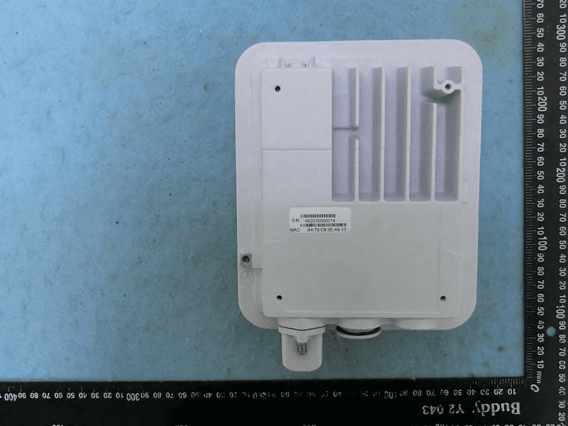
S9GT350D
Mar 10, 2021Access point
Equipment Class
DTS - Digital Transmission System