S9GMF7211Multimedia Wireless Access Point
Ruckus Wireless, Inc.
Click to zoom
Application Details
- Equipment Class
- DTS - Digital Transmission System
- Date of Grant
- Apr 08, 2010
- Application Purpose
- Original Equipment
- Date of Application
- Apr 08, 2010
- Equipment Note
- Multimedia Wireless Access Point
- Frequency Range
- 2422.00000000 - 2452.00000000
- Company
- Ruckus Wireless, Inc.
- Country
- United States
Documents & Files
Document Text
Text extracted from the exhibit documents filed with the FCC. Open a document above to read the original.
Users Manual
Copyright © 2010 Ruckus Wireless, Inc. Published March 2010, Part Number 800-70273-001 MetroFlex 7211 Broadband Gateway Quick Setup Guide This Quick Setup Guide provides step-by-step instructions on how to set up your Ruckus Wireless MetroFlex 7211 Broadband Gateway. After completing the steps described in this Guide, you will be able to place the device at your site and provide wireless network access to users. B EFORE Y OU B EGIN Before deploying Ruckus Wireless products, please check for the latest software and the release documentation.• Release Notes are available at http://support.ruckuswir eless.com/documents . • User Guides are available at http://support.ruckuswir eless.com/documents . • Software Upgrades are available at http://support.ruckuswireless.com/software . • Open Source information is available at http://support.ruckuswir eless.com/open_source . P ACKAGE C ONTENTS • One Ruckus Wireless MetroFlex 7211 Broadband Gateway unit • One AC power adapter • One mounting kit (with printed instructions) •This Quick Setup Guide S ETUP R EQUIREMENTS • A computer running Windows 7, Vista, XP, or Windows 2000 • One or more of the following: • A modem (DSL or cable), E1/T1 router, or other device provided by your Internet Service Provider, that brings Internet access to your site. • A network switch or a DSL/Internet gateway device. D EFAULT S ETTINGS • The default IP address is 192.168.0.1 . • The subnet mask is 255.255.255.0 . To gain administrative control of the device, you must set your computer’s network interface card to obtain an IP address automatically.Proceed to the next section for instructions on configuring your IP address.S TEP 1: C ONFIGURE Y OUR C OMPUTER ’ S IP A DDRESS 1 Start the Network Connections properties dialog box:• On Windows 2000, click Start > Settings > Network , and then click Dialup Connections . • On Windows XP, click Start > Settings > Control Panel > Network Connections . 2 Double-click the icon for the Local Area Connection designated for your home network. This is not the same icon as your home wireless network. 3 In the Local Area Connection Properties window, select Internet Protocol (TCP/IP) , and then click Properties . 4 Select Obtain an IP address automatically , and then click OK to exit the TCP/IP Properties window. 5 Click OK to exit the Local Area Connection Properties win- dow. S TEP 2: C ONNECT AND C ONFIGURE THE D EVICE Follow these steps to set up the device and gain administrative access to the management interface:1 Remove the device from the packaging and place it next to your computer. 2 Connect the AC power adapter to the device, and then plug the other end into a power outlet or to a surge pro-tector that is plugged into a power outlet. 3 Connect one end of the CAT5 Ethernet cable to the Ether-net port on your computer, and then connect the other en to the Ethernet port on the device. 4 On your computer, open a browser window, and then enter 192.168.0.1 in the address or location bar. 5 When the login screen appears, enter the username and password listed on the bottom of the unit. Then click the Log On button. The Quick Wizard page appears. If you want to use the wizard, follow the instructions to complete configuration. Otherwise, go to the next step for manual configuration. 6 On the Configuration > Wireless menu, change the default wireless network name (SSID) of this device to match the SSID of the AP you intend to connect to. 7 If security settings are enabled on the AP to which the device is connecting, make sure that you duplicate the exact settings on the device. 8 Click Update to save the changes. If you want to change other settings on this page, refer to the information provided under the Need Help button. The initial configuration is now complete. Click Reboot to make the change take effect. F OR M ORE I NFORMATION You can now use the wireless network to log into the device’s management interface. Use the management interface to review and fine-tune a wide range of device settings. For more information on how to configure the device from the management interface, refer to the online help.If you are encounter issues connecting to the management interface or if wireless clients are unable to associated with the device, perform the basic troubleshooting steps below. Copyright © 2010 Ruckus Wireless, Inc. Published March 2010, Part Number 800-70273-001 T ROUBLESHOOTING If wireless clients are unable to connect to the device, perform these basic troubleshooting steps.Check the Wireless and Security SettingsDo the following to verify that the wireless network name (SSID) and security settings on the device match those of your wireless network:1 Use an Ethernet cable to connect your computer to the device. 2 Set your computer’s network interfa ce card to obtain an IP address automatically. 3 Open a Web browser window, and then, in your browser’s address or location bar, enter 192.168.0.1 . 4 On the login page, enter the user name and password listed at the bottom of the unit. 5 Click Login . 6 On the menu, click Configuration > Wireless . 7 Click the Metro WLAN tab. 8 Verify that the MetroFlex 7211 Broadband Gateway’s wire-less and security settings match those of your remote AP. Check the LEDs• Make sure you are using the power adapter supplied by Ruckus Wireless. • Make sure the Power LED is on. If it is off, make sure that the power cord is properly connected to the device and that the power supply adapter is properly connected to a functioning power outlet. If the error persists, you have a hardware prob-lem and should contact technical support. • If you have a computer connected to the device, verify that the Network LED is on. Make sure the Ethernet cable connec-tions are secure on the device and your computer. The Net-work LED on the device indicates link when the cable connection is solidly connected to the port on the gateway and to the port on your computer. • Make sure that the Wireless LED is either steady or f…
Text truncated - open the document above for the full version.
Cover Letter(s)
FEDERAL COMMUNICATIONS COMMISSIONS Authorization and Evaluation Division 7435 Oakland Mills Road Columbia, MD 21046 February 16, 2010 Re: Request for Confidentiality Dear Examiner: In reference to the application under FCC ID: S9GMF7211, and pursuant to Sections 0.457(d)(1)(ii) and 0.459 of the Commission's Rules, the Applicant hereby requests confidential treatment of the accompanying information as outlined below: Schematics Block diagram Theory of Operation Antenna specifications The above materials contain trade secrets and proprietary information not customarily released to the public. The public disclosure of these matters might be harmful to the Applicant and provide unjustified benefits to its competitors. In additional to above mentioned documents, pursuant to Public Notice DA 04-1705 of the Commission’s policy, in order to comply with the marketing regulations in 47 CFR §2.803 and the importation rules in 47 CFR §2.1204, while ensuring that business sensitive information remains confidential until the actual marketing of newly authorized devices. We are requesting the commission to grant short-term confidentiality request on the following attachments: Internal and External Photographs Test Configuration Photographs It is our understanding that all measurement test reports, FCC ID label format and correspondent during certification review process cannot be granted as confidential documents and those information will be available for public review once the grant of equipment authorization is issued. The Applicant understands that pursuant to Rule 0.457(d)(1)(ii), disclosure of this Application and all accompanying documentation will not be made before the date of the Grant for this application. Sincerely, Craig Owens Director, Hardware Engineering 880 West Maude Avenue, Suite 101 TEL + .650.265.4200 Sunnyvale, CA 94085 USA FAX +.480.738.2065 www.ruckuswireless.com
External Photos
Ruckus Wireless, Inc. FCC ID: S9GMF7211, IC: 5912A-MF7211 Report Number: R0912181-247 Page 109 of 118 FCC Part15.247 & IC RSS-210 Test Report 15 EXHIBIT C - EUT Photographs 15.1 EUT (Integral Antenna) – Front View 15.2 EUT (Integral Antenna) – Rear View Ruckus Wireless, Inc. FCC ID: S9GMF7211, IC: 5912A-MF7211 Report Number: R0912181-247 Page 110 of 118 FCC Part15.247 & IC RSS-210 Test Report 15.3 EUT (Integral Antenna) – Side View 15.4 EUT (External Antenna) – Front View Ruckus Wireless, Inc. FCC ID: S9GMF7211, IC: 5912A-MF7211 Report Number: R0912181-247 Page 111 of 118 FCC Part15.247 & IC RSS-210 Test Report 15.5 EUT (External Antenna) – Rear View 15.6 EUT (External Antenna) – Side View Ruckus Wireless, Inc. FCC ID: S9GMF7211, IC: 5912A-MF7211 Report Number: R0912181-247 Page 112 of 118 FCC Part15.247 & IC RSS-210 Test Report 15.7 EUT (POE Adapter) – Top View 15.8 EUT (POE Adapter) – Bottom View Ruckus Wireless, Inc. FCC ID: S9GMF7211, IC: 5912A-MF7211 Report Number: R0912181-247 Page 113 of 118 FCC Part15.247 & IC RSS-210 Test Report 15.9 EUT (POE Adapter) – Front View 15.10 EUT AD/DC Adapter – Top View Ruckus Wireless, Inc. FCC ID: S9GMF7211, IC: 5912A-MF7211 Report Number: R0912181-247 Page 114 of 118 FCC Part15.247 & IC RSS-210 Test Report 15.11 EUT External Antenna – Top View
ID Label/Location Info
860-77738-001-1 Made in XXX Default IP Address: 192.168.0.1 User name=super Password=sp-admin MediaFlex 7211 Access Point N420 1. Replace “XXX” with the country of manufacture 2. Dielines/cutlines do not print 3. P/N 877-77738-001 Rev. 1 4. Colors: BLACK PMS 021C 12V1.0A FCC ID: S9GMF7211 IC: 5912A-MF7211
RF Exposure Info
Ruckus Wireless, Inc. FCC ID: S9GMF7211, IC: 5912A-MF7211 Report Number: R0912181-247 Page 101 of 118 FCC Part15.247 & IC RSS-210 Test Report 12 FCC §15.247 (i), §2.1091 & IC RSS-102 - RF Exposure 12.1 Applicable Standard According to §15.247(i) and §1.1307(b)(1), systems operating under the provisions of this section shall be operated in a manner that ensures that the public is not exposed to radio frequency energy level in excess of the Commission’s guidelines. According to §1.1310 and §2.1091 RF exposure is calculated. Limits for General Population/Uncontrolled Exposure Frequency Range (MHz) Electric Field Strength (V/m) Magnetic Field Strength (A/m) Power Density (mW/cm 2 ) Averaging Time (minutes) Limits for General Population/Uncontrolled Exposure 0.3-1.34 614 1.63 *(100) 30 1.34-30 824/f 2.19/f *(180/f 2 ) 30 30-300 27.5 0.073 0.2 30 300-1500 / / f/1500 30 1500-100,000 / / 1.0 30 f = frequency in MHz * = Plane-wave equivalent power density Before equipment certification is granted, the procedure of IC RSS-102 must be followed concerning the exposure of humans to RF fields. According to RSS-102 Issue 2 section 4.1, RF limits used for general public will be applied to the EUT. Frequency Range (MHz) Electric Field (V/m rms) Magnetic Field (A/m rms) Power Density (W/m 2 ) Time Averaging (min) 0.003 - 1 280 2.19 - 6 1 - 10 280 / f 2.19 / f - 6 10 - 30 28 2.19 / f - 6 30 – 300 28 0.073 2* 6 300 – 1 500 1.585 f 0.5 0.0042 f 0.5 f / 150 6 1 500 – 15 000 61.4 0.163 10 6 15 000 – 150 000 61.4 0.163 10 616000 / f 1.2 150 000- 300 000 0.158 f 0.5 4.21 x 10 -4 f 0.5 6.67 x 10 -5 f 616000 / f 1.2 Note: ƒ is frequency in MHz * Power density limit is applicable at frequencies greater than 100 MHz Ruckus Wireless, Inc. FCC ID: S9GMF7211, IC: 5912A-MF7211 Report Number: R0912181-247 Page 102 of 118 FCC Part15.247 & IC RSS-210 Test Report 12.2 MPE Prediction Prediction of MPE limit at a given distance, Equation from OET Bulletin 65, Edition 97-01 S = PG/4πR² Where: S = power density P = power input to antenna G = power gain of the antenna in the direction of interest relative to an isotropic radiator R = distance to the center of radiation of the antenna Maximum peak output power at antenna input terminal (dBm): 21.42 Maximum peak output power at antenna input terminal (mW): 138.67 Prediction distance (cm): 20 Prediction frequency (MHz): 2412 Maximum Antenna Gain, typical (dBi): 9.0 Maximum Antenna Gain (numeric): 7.94 Power density of prediction frequency at 20.0 cm (mW/cm 2 ): 0.219 Power density of prediction frequency at 20.0 cm (W/m 2 ): 2.19 MPE limit for uncontrolled exposure at prediction frequency (mW/cm 2 ): 1.0 MPE limit for uncontrolled exposure at prediction frequency (W/m 2 ): 10 12.3 Test Result The device is compliant with the requirement MPE limit for uncontrolled exposure. The maximum power density at the distance of 20 cm is 0.219mW/cm 2 (2.19 W/m 2 ).Limit is 1mW/cm 2 (10W/m 2 ).
Test Report
Note: This test report is prepared for the customer shown above and for the device described herein. It may not be duplicated or used in part without prior written consent from Bay Area Compliance Laboratories Corp. This report must not be used by the customer to claim product certification, approval, or endorsement by NVLAP*, NIST, or any agency of the Federal Government. * This report may contain data that are not covered by the NVLAP accreditation and are marked with an asterisk “*” (Rev.2) FCC PART 15.247 IC RSS-210, ISSUE 7, JUNE 2007 TEST AND MEASUREMENT REPORT For Ruckus Wireless, Inc. 880 West Maude Avenue, Suite 101, Sunnyvale, CA 94085, USA FCC ID: S9GMF7211 IC: 5912A-MF7211 Report Type: Original Report Product Type: 802.11b/g/n Access Point Test Engineer: Dennis Huang Report Number: R0912181-247 Report Date: 2010-04-08 Reviewed By: Boni Baniqued EMC/RF Supervisor Prepared By: (84) Bay Area Compliance Laboratories Corp. 1274 Anvilwood Avenue, Sunnyvale, CA 94089, USA Tel: (408) 732-9162 Fax: (408) 732 9164 Ruckus Wireless, Inc. FCC ID: S9GMF7211, IC: 5912A-MF7211 Report Number: R0912181-247 Page 2 of 118 FCC Part15.247 & IC RSS-210 Test Report TABLE OF CONTENTS 1 GENERAL INFORMATION....................................................................................................................................... 6 1.1 PRODUCT DESCRIPTION FOR EQUIPMENT UNDER TEST (EUT)................................................................................. 6 1.2 MECHANICAL DESCRIPTION OF EUT ....................................................................................................................... 6 1.3 OBJECTIVE............................................................................................................................................................... 6 1.4 RELATED SUBMITTAL(S)/GRANT(S) ........................................................................................................................ 6 1.5 TEST METHODOLOGY.............................................................................................................................................. 6 1.6 MEASUREMENT UNCERTAINTY...............................................................................................................................7 1.7 TEST FACILITY........................................................................................................................................................ 7 2 SYSTEM TEST CONFIGURATION .......................................................................................................................... 8 2.1 JUSTIFICATION......................................................................................................................................................... 8 2.2 EUT EXERCISE SOFTWARE...................................................................................................................................... 8 2.3 SPECIAL ACCESSORIES............................................................................................................................................ 8 2.4 EQUIPMENT MODIFICATIONS................................................................................................................................... 8 2.5 LOCAL SUPPORT EQUIPMENT.................................................................................................................................. 8 2.6 EUT INTERNAL CONFIGURATION DETAILS.............................................................................................................. 9 2.7 EXTERNAL I/O CABLING LIST AND DETAILS........................................................................................................... 9 3 SUMMARY OF TEST RESULTS ............................................................................................................................. 10 4 FCC §15.203 & IC RSS-GEN §7.1.4 – ANTENNA REQUIREMENT ................................................................... 11 4.1 APPLICABLE STANDARD........................................................................................................................................ 11 4.2 RESULT.................................................................................................................................................................. 11 5 FCC §15.207 & IC RSS-GEN §7.2.2- CONDUCTED EMISSIONS ....................................................................... 12 5.1 APPLICABLE STANDARD........................................................................................................................................ 12 5.2 TEST SETUP........................................................................................................................................................... 12 5.3 TEST PROCEDURE.................................................................................................................................................. 12 5.4 TEST EQUIPMENT LIST AND DETAILS.................................................................................................................... 13 5.5 TEST SETUP BLOCK DIAGRAMS............................................................................................................................. 13 5.6 TEST ENVIRONMENTAL CONDITIONS..................................................................................................................... 14 5.7 TEST RESULTS....................................................................................................................................................... 14 5.8 CONDUCTED EMISSIONS TEST PLOTS AND DATA.................................................................................................. 15 6 FCC §15.247(A)(2) & IC RSS-210 §A8.2(A) – 6 DB OCCUPIED BANDWIDTH ................................................ 19 6.1 APPLICABLE STANDARD..........................................................................…
Text truncated - open the document above for the full version.
Test Setup Photos
Ruckus Wireless, Inc. FCC ID: S9GMF7211, IC: 5912A-MF7211 Report Number: R0912181-247 Page 105 of 118 FCC Part15.247 & IC RSS-210 Test Report 14 EXHIBIT B – Test Setup Photographs 14.1 Conducted Emissions – Front View (AC/DC Adapter) 14.2 Conducted Emissions – Side View (AC/DC Adapter) Ruckus Wireless, Inc. FCC ID: S9GMF7211, IC: 5912A-MF7211 Report Number: R0912181-247 Page 106 of 118 FCC Part15.247 & IC RSS-210 Test Report 14.3 Conducted Emissions – Front View (POE) 14.4 Conducted Emissions – Side View (POE) Ruckus Wireless, Inc. FCC ID: S9GMF7211, IC: 5912A-MF7211 Report Number: R0912181-247 Page 107 of 118 FCC Part15.247 & IC RSS-210 Test Report 14.5 Spurious Radiated Emissions (Below 1 GHz) – Front View 14.6 Spurious Radiated Emissions (Below 1 GHz) – Rear View Ruckus Wireless, Inc. FCC ID: S9GMF7211, IC: 5912A-MF7211 Report Number: R0912181-247 Page 108 of 118 FCC Part15.247 & IC RSS-210 Test Report 14.7 Spurious Radiated Emissions (Above 1 GHz) – Front View 14.8 Spurious Radiated Emissions (Above 1 GHz) – Rear View
Contact Information
Applicant
Ivaylo Tankov(Principal Wireless Compliance Engineering)
Test Firm
Bay Area Compliance LaboratoryJohn Chan
Technical Specifications
| # | Rule Parts | Frequency Range | Power Output |
|---|---|---|---|
| 4 | 15C | 2.42 GHz - 2.45 GHz | 122.50 mW |
Other Applications from Ruckus Wireless, Inc.
S9GR650P
Jul 11, 2021R650p Access Point
Equipment Class
DTS - Digital Transmission System
S9GR350
Jun 30, 2021Access Point
Equipment Class
NII - Unlicensed National Information Infrastructure TX
S9GR550P
Jun 30, 2021Wireless Access Point
Equipment Class
DTS - Digital Transmission System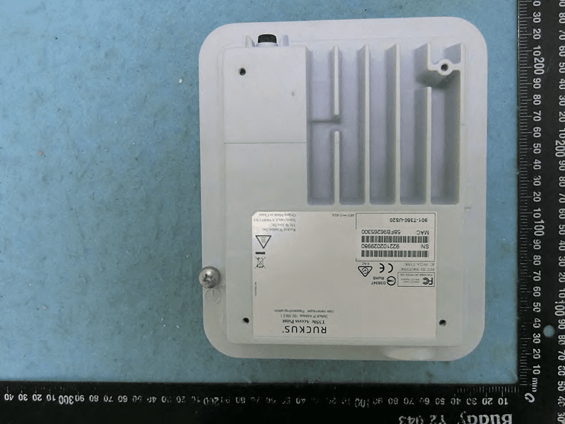
S9GT350C
Mar 23, 2021Access point
Equipment Class
NII - Unlicensed National Information Infrastructure TX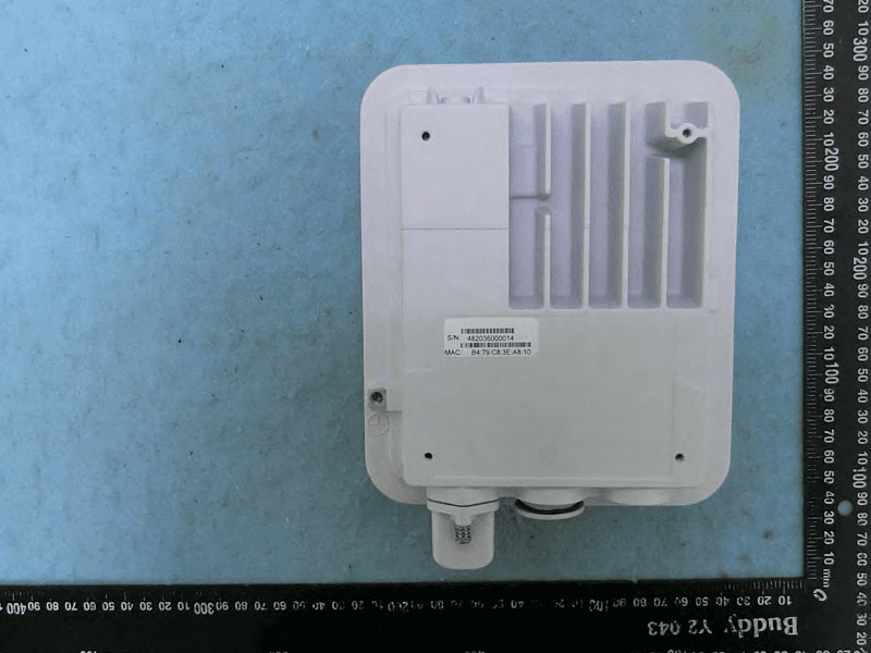
S9GT350D
Mar 10, 2021Access point
Equipment Class
DTS - Digital Transmission System