S9GMP2N33A802.11b/g/n module
Ruckus Wireless, Inc.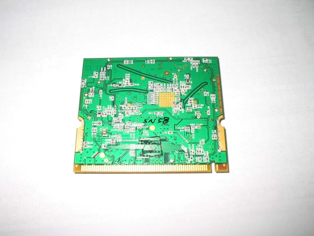
Click to zoom
Application Details
- Equipment Class
- DTS - Digital Transmission System
- Date of Grant
- Jan 15, 2008
- Application Purpose
- Original Equipment
- Date of Application
- Jan 15, 2008
- Equipment Note
- 802.11b/g/n module
- Frequency Range
- 2412.00000000 - 2462.00000000
- Company
- Ruckus Wireless, Inc.
- Country
- United States
Documents & Files
Document Text
Text extracted from the exhibit documents filed with the FCC. Open a document above to read the original.
Users Manual
Federal Communications Commission Notices This product complies with Part 15 of the FCC Rules. Operation is subject to the following two conditions: (1) this device may not cause harmful interference, and (2) this device must accept any interference received, including interference that may cause undesired operation. Radiation Exposure Statement This equipment complies with FCC radiation exposure limits set forth for an uncontrolled environment. This equipment should be installed and operated with minimum distance 20cm between the radiator and your body. This equipment shall not be colocated with any other transmitter. Harmful Interference Notice This product has been tested and complies with the specifications for a Class B digital device, pursuant to Part 15 of the FCC Rules. These limits are designed to provide reasonable protection against harmful interference in a residential installation. This equipment generates, uses, and can radiate radio frequency energy and, if not installed and used according to the instructions, may cause harmful interference to radio communications. However, there is no guarantee that interference will not occur in a particular installation. If this equipment does cause harmful interference to radio or television reception, which is found by turning the equipment off and on, the user is encouraged to try to correct the interference by one or more of the following measures: • Reorient or relocate the receiving antenna • Increase the separation between the equipment or devices • Connect the equipment to an outlet other than the receiver's • Consult a dealer or an experienced radio/TV technician for assistance Changes or modifications to this equipment that have not been approved by Ruckus Wireless may void the user's authority to operate this equipment. External Antennas This device has been designed to operate with the antennas listed below, and having a maximum gain of 9 dBi. Antennas not included in this list or having a gain greater than 9 dBi are strictly prohibited for use with this device. The required antenna impedance is 50 ohms. • 9dBi patch antenna • 9dBi omni-directional antenna • 9dBi Ruckus Wireless “Tomahawk” antenna To reduce potential radio interference to other users, the antenna type and its gain should be so chosen that the equivalent isotropically radiated power (e.i.r.p.) is not more than that permitted for successful communication. Industry Canada Statement This device complies with Industry Canada ICES-003 and RSS210 rules. Operation is subject to the following two conditions: 1. This device may not cause interference and 2. This device must accept any interference, including interference that may cause undesired operation of the device. Règlement d’Industry Canada Cet appareil est conforme aux normes NMB003 et RSS210 d'Industrie Canada. Le fonctionnement est soumis aux conditions suivantes : 1. Ce périphérique ne doit pas causer d'interférences; 2. Ce périphérique doit accepter toutes les interférences reçues, y compris celles qui risquent d'entraîner un fonctionnement indésirable. Australia Statement This device complies with the ACMA requirements for a Wi-Fi device namely Radio Communications (Low Impact Potential Devices) Class Licence 2000 Amd. 1:2007 and Radiocommunications (Compliance Labelling – Electromagnetic Radiation) Notice 2003. The equipment complies with the ACMA requirements for radiation exposure for a "general user/non-aware user". This equipment should be installed and operated with a minimum distance of 20 cm between the radiator and your body. This equipment complies with the Australian safety requirements and should only used with the specified power adapter carrying a C-tick N136 and Electrical Approval Number V06649. European Union Notices Compliance Information for 2.4-GHz Wireless Products The following standards were applied during the assessment of the product against the requirements of the Directive 1999/5/EC: • Radio: EN 300 328 • EMC: EN 301 489-1, EN 301 489-17 • Safety: IEC 60950 National Restrictions This product may be used in all EU countries (and other countries following the EU directive 1999/5/EC) without any limitation except for the countries mentioned below: Ce produit peut être utilisé dans tous les pays de l’UE (et dans tous les pays ayant transposés la directive 1999/5/CE) sans aucune limitation, excepté pour les pays mentionnés ci-dessous: Questo prodotto è utilizzabile in tutte i paesi EU (ed in tutti gli altri paesi che seguono le direttive EU 1999/5/EC) senza nessuna limitazione, eccetto per i paesii menzionati di seguito: Das Produkt kann in allen EU Staaten ohne Einschränkungen eingesetzt werden (sowie in anderen Staaten die der EU Direktive 1999/5/CE folgen) mit Außnahme der folgenden aufgeführten Staaten: France In case the product is used outdoors, the output power is restricted in some parts of the band. See the table below or check http://www.arcep.fr/ for more details. Dans la cas d’une utilisation en extérieur, la puissance de sortie est limitée pour certaines parties de la bande. Reportezvous à la table 1 ou visitez http://www.arcep.fr/ pour de plus amples détails. Location Frequency Range (MHz) Power (EIRP) Indoor (No restrictions) 2400-2483.5 100 mW (20 dBm) Outdoor 2400-2454 [2454-2483.5] 100 mW (20 dBm) [10 mW(10 dBm)] Italy This product meets the National Radio Interface and the requirements specified in the National Frequency Allocation Table for Italy. Unless operating within the boundaries of the owner’s property, the use of this 2.4 GHz Wireless LAN product requires a ‘general authorization’. Please check with http://www.comunicazioni.it/it/ for more details. Questo prodotto è conforme alla specifiche di Interfaccia Radio Nazionali e rispetta il Piano Nazionale di ripartizione delle frequenze in Italia. Se non viene installato all’interno del proprio fondo, l’utilizzo di prodotti Wireless. Belgium The Belgian Institute for Postal Services and Telecommunications (BIPT…
Text truncated - open the document above for the full version.
Users Manual
User Guide Ruckus Wireless ZoneFlex 2925/2942/7942 Access Point ii Legal Information Copyright © 2007 Ruckus Wireless, Inc. All rights reserved. Trademarks Ruckus Wireless ZoneFlex™ 2825/2925/2942 Access Points, BeamFlex™, MediaFlex™, MediaFlex 2900 Multimedia Access Point, MediaFlex 2501 Multimedia Wireless Adapter, 2825 Wire- less Multimedia Router, 2111 Wireless Multimedia Adapter, and MM2211/MM2225 Metro Broadband Gateways are trademarks of Ruckus Wireless Web Interface All other brands and product names are registered trademarks of their respective holders. Statement of Conditions In the interest of improving internal design, operational function, and/or reliability, Ruckus Wireless, Inc. reserves the right to make changes to the products described in this document without notice. Ruckus Wireless, Inc. does not assume any liability that may occur due to the use or application of the product(s) or circuit lay- out(s) described herein. Information to the user The user’s manual or instruction manual for an intentional or unin- tentional radiator shall caution the user that changes or modifica- tions not expressly approved by the party responsible for compliance could void the user’s authority to operate the equip- ment. In cases where the manual is provided only in a form other than paper, such as on a computer disk or over the Internet, the information required by this section may be included in the manual in that alternative form, provided the user can reasonably be expected to have the capability to access information in that form. 22 Class B (CISPR 22).(Other agency certifications go here) Part number: USM-ZF2925-RKS1-072507-01 EDITION: July 25, 2007 -- vA Contact Information Headquarters — United States Telephone U.S.: +1 408-111-2345 Support http://www.ruckuswireless.com Web/email www.ruckuswireless.com iii Contents Chapter 1: Are You a Wi-Fi HotspotOperator?. . . . . . . . . . . . . . . . . . . . . .1 Where exactly should you place the Access Point?. . . . . . . . . . . . . . . . . . . . 3 What’s next?. . . . . . . . . . . . . . . . . . . . . . . . . . . . . . . . . . . . . . . . . . . . . . 3 Chapter 2: Installation, Setup, and Placementof the AP. . . . . . . . . . . . . .4 What’s in the Package . . . . . . . . . . . . . . . . . . . . . . . . . . . . . . . . . . . . . . . 5 Features of the Access Point . . . . . . . . . . . . . . . . . . . . . . . . . . . . . . . . . . . 5 Preparing the Access Point for Network Use . . . . . . . . . . . . . . . . . . . . . . . . 9 Troubleshooting the Initial Setup Connection . . . . . . . . . . . . . . . . . . . . . . 15 What’s Next?. . . . . . . . . . . . . . . . . . . . . . . . . . . . . . . . . . . . . . . . . . . . . 16 Chapter 3: After the Installation (Post-Installation Setup) . . . . . . . . . . . . . . . . . . . . . . . . . . . . . . . . . . . . .17 Opening the Web User Interface . . . . . . . . . . . . . . . . . . . . . . . . . . . . . . . 18 Changing the Administrator Login Settings . . . . . . . . . . . . . . . . . . . . . . . . 20 Activating other Administrator Access Options . . . . . . . . . . . . . . . . . . . . . 21 Changing the IP Address . . . . . . . . . . . . . . . . . . . . . . . . . . . . . . . . . . . . 22 Customizing Common Wireless Configuration . . . . . . . . . . . . . . . . . . . . . . 24 Customizing Wireless Hotspot Settings. . . . . . . . . . . . . . . . . . . . . . . . . . . 27 Customizing Wireless WEP Encryption . . . . . . . . . . . . . . . . . . . . . . . . . . . 29 Customizing Wireless WPA Encryption . . . . . . . . . . . . . . . . . . . . . . . . . . . 30 Customizing 802.1x (Settings) . . . . . . . . . . . . . . . . . . . . . . . . . . . . . . . . 32 Reviewing Current VLAN IDs . . . . . . . . . . . . . . . . . . . . . . . . . . . . . . . . . 34 Chapter 4: Managing the Access Point. . . . . . . . . . . . . . . . . . . . . . . . . . .35 Maintaining your HotSpot AP. . . . . . . . . . . . . . . . . . . . . . . . . . . . . . . . . . 36 Rate Limiting HotSpots. . . . . . . . . . . . . . . . . . . . . . . . . . . . . . . . . . . . . . 41 Access Controls. . . . . . . . . . . . . . . . . . . . . . . . . . . . . . . . . . . . . . . . . . . 44 VLANs . . . . . . . . . . . . . . . . . . . . . . . . . . . . . . . . . . . . . . . . . . . . . . . . . 46 Renewing or Releasing DHCP. . . . . . . . . . . . . . . . . . . . . . . . . . . . . . . . . . 51 Upgrading the AP Firmware. . . . . . . . . . . . . . . . . . . . . . . . . . . . . . . . . . . 51 Rebooting the AP. . . . . . . . . . . . . . . . . . . . . . . . . . . . . . . . . . . . . . . . . . 53 Restoring the AP to Factory Default Settings. . . . . . . . . . . . . . . . . . . . . . . 54 Chapter 5: Monitoring Activity in the Access Point. . . . . . . . . . . . . . . . . .55 Monitoring WLAN Use. . . . . . . . . . . . . . . . . . . . . . . . . . . . . . . . . . . . . . . 56 Monitoring Local Services . . . . . . . . . . . . . . . . . . . . . . . . . . . . . . . . . . . . 56 iv Activating the AP Log and Sending the Log to a Syslog Server . . . . . . . . . . . . . . . . . . . . . . . . . . . . . . . . . . . . . . . . . . . . 57 Reviewing the Latest Log File Entries . . . . . . . . . . . . . . . . . . . . . . . . . . . . 58 Sending a Copy of the Log File to Support Staff. . . . . . . . . . . . . . . . . . . . . 58 Running Diagnostics on NetworkConnections . . . . . . . . . . . . . . . . . . . . . . 60 1 CHAPTER 1 Are You a Wi-Fi HotspotOperator? Then you’ll appreciate learning about your new Ruckus Wireless hotspot access point, before you get started. What can a Hotspot Access Point do for you? You’re occupying a large space, with lots of users, and you’d like to make it a Wi-Fi hotzone. Let’s make it easy for you; there’s an active Internet connection from a local ISP (DSL, cable or other), and you’ve got a modem—as shown here. FIGURE 1-1 Ruckus Wireless ZoneFlex 2925/2942/7942 User Guide | Are You a Wi-Fi HotspotOperator? 2 Is there a switch connected to the modem? If not, you’ll…
Text truncated - open the document above for the full version.
Cover Letter(s)
Elliott TCB 684 West Maude Ave. Sunnyvale, CA 94085 December 6, 2007 Re: Request for Confidentiality Dear Examiner: In reference to the application under FCC ID: S9G79X2-XXX, and pursuant to Sections 0.457(d)(1)(ii) and 0.459 of the Commission's Rules, the Applicant hereby requests confidential treatment of the accompanying information as outlined below: Schematics Block diagram Theory of Operation The above materials contain trade secrets and proprietary information not customarily released to the public. The public disclosure of these matters might be harmful to the Applicant and provide unjustified benefits to its competitors. In additional to above mentioned documents, pursuant to Public Notice DA 04-1705 of the Commission’s policy, in order to comply with the marketing regulations in 47 CFR §2.803 and the importation rules in 47 CFR §2.1204, while ensuring that business sensitive information remains confidential until the actual marketing of newly authorized devices. We are requesting the commission to grant short-term confidentiality request on the following attachments: Internal and External Photographs Test Configuration Photographs It is our understanding that all measurement test reports, FCC ID label format and correspondent during certification review process cannot be granted as confidential documents and those information will be available for public review once the grant of equipment authorization is issued. The Applicant understands that pursuant to Rule 0.457(d)(1)(ii), disclosure of this Application and all accompanying documentation will not be made before the date of the Grant for this application. Sincerely, Craig Owens Director, Hardware Engineering 880 West Maude Avenue, Suite 101 TEL + .650.265.4200 Sunnyvale, CA 94085 USA FAX +.480.738.2065 www.ruckuswireless.com
Cover Letter(s)
Modular Approval is being requested for this device: FCC ID S9GMP2N33A. There are eight requirements that the device must meet for full modular approval. The following paragraphs detail these requirements and the manner in which the device meets them. The module meets all of the technical specifications applicable to the frequency band of operation. Ruckus Wireless does not intend to sell the modules. They will only be used for installation in Ruckus products. Therefore, no description of the module's use is included in the user's manual. The manual only describes the complete product incorporating the module. Ruckus Wireless understands that the complete product shall be labeled as described below. The module has its own RF shielding. The module contains a shield that covers all radio components. All modulation and data input(s) are buffered. Data to the modulation circuit is buffered on the module via U5. The module has its own power supply regulation and local reference oscillator. The module contains its own local oscillator. The module is specified to fit into a mini-PCI slot, which is specified to be regulated to +/-300mV. The module has been designed and tested to tolerate this variation. The module will only be used with Ruckus Wireless host units. Any host unit we use with the module will have the same power supply regulation used for this application. Two regulators that satisfy this requirement are the Texas Instruments TPS23750 and the Monolithic Power Systems MP38872. The modular transmitter must comply with the antenna requirements of Section 15.203 and 15.204(c). The certification submission contains a detailed description of the configuration of all antennas that will be used with the module. The module connects to its antenna via a U.FL connector. This is a non-standard connector. For Industry Canada, the module meets certification labeling requirements. Host devices that contain separately certified modules do not need to be re-certified, provided that they meet the following conditions: 880 West Maude Avenue, Suite 101 TEL + .650.265.4200 Sunnyvale, CA 94085 USA FAX +.480.738.2065 www.ruckuswireless.com • The host device, as a stand alone unit without any separately certified modules, complies with all applicable Radio Standards Specifications. • The host device and all the separately certified modules it contains jointly meet the safety requirements of RSS-102, if applicable. • The host device complies with the certification labeling requirements of each of the modules it contains. The module is appropriately labeled (refer to the label and label location drawings contained within this application). For the FCC, the modular transmitter must be tested in a stand-alone configuration, i.e., the module must not be inside another device during testing. This is intended to demonstrate that the module is capable of complying with Part 15 emission limits regardless of the device into which it is eventually installed. Unless the transmitter module will be battery powered, it must comply with the AC line conducted requirements found in Section 15.207. Test data contained in this application is for the device tested as a stand-alone device. Radiated spurious emissions data and AC conducted emissions data demonstrating compliance with the requirements of Part 15 of the FCC rules for intentional radiators has been provided. For the FCC, the modular transmitter must be labeled with its own FCC ID number, and, if the FCC ID is not visible when the module is installed inside another device, then the outside of the device into which the module is installed must also display a label referring to the enclosed module. This exterior label can use wording such as the following: “Contains Transmitter Module FCC ID: XYZMODEL1” or “Contains FCC ID: XYZMODEL1.” The module is appropriately labeled (refer to the label and label location drawings contained within this application). The modular transmitter must comply with any applicable RF exposure requirements. The module meets the requirements for a mobile device that may be used at separation distances of more than 20cm from the human body. Refer to the MPE calculation. Sincerely, Craig Owens Director, Hardware Engineering 880 West Maude Avenue, Suite 101 TEL + .650.265.4200 Sunnyvale, CA 94085 USA FAX +.480.738.2065 www.ruckuswireless.com
Cover Letter(s)
Elliott TCB 684 West Maude Ave. Sunnyvale, CA 94085 November 8, 2007 Gentlemen: This is your letter of authorization to accept our appointment of Elliott Laboratories, Inc. as our Agent for Ruckus Wireless, 880 W. Maude Ave, Suite 101, Sunnyvale, CA 94085, to sign applications before Elliott TCB and to make representations to you on our behalf. Elliott Laboratories, Inc. is to receive and exchange data between our company and Elliott TCB. Sincerely, Craig Owens Director, Hardware Engineering 880 West Maude Avenue, Suite 101 TEL + .650.265.4200 Sunnyvale, CA 94085 USA FAX +.480.738.2065 www.ruckuswireless.com
ID Label/Location Info
Colors: BLACK Model: MP2N33A FCC ID:S9GMP2N33A IC:5912A-MP2N33A 860-76188-001
RF Exposure Info
EMC Test Data Client: Contact: Standard: Test Specific Details General Test Configuration Yes/No Yes Device complies with Power Density requirements at 20cm separation: If not, required separation distance (in cm): Modifications Made During Testing No modifications were made to the EUT during testing Deviations From The Standard No deviations were made from the requirements of the standard. Calculation uses the free space transmission formula: S = (PG)/(4 πd 2 ) Where: S is power density (W/m 2 ), P is output power (W), G is antenna gain relative to isotropic, d is separation distance from the transmitting antenna (m). Summary of Results Test Engineer: David Bare Maximum Permissible Exposure Objective: Evaluate the RF Exposure requirements per FCC 1.1310, 2.1091 and RSS-102. Date of Test: 12/17/2007 Craig Owens FCC Part 15.247/RSS-210Class: N/A Ruckus WirelessJob Number: J68610 Model: Retriever module T-Log Number: T68973 Account Manager: Dean Eriksen T68973MPE 17-Dec-07Page 1 of 3 EMC Test Data Client: Contact: Standard: Craig Owens FCC Part 15.247/RSS-210Class: N/A Ruckus WirelessJob Number: J68610 Model: Retriever module T-Log Number: T68973 Account Manager: Dean Eriksen Use: General Antenna:9dBi 802.11b mode Cable AntPower Freq.LossGainat AntEIRP MHzdBmmW*dBdBidBmmW 241222.9195.00922.91548.82 243723.3213.80923.31698.24 246223.4218.80923.41737.80 For the cases where S > the MPE Limit Fre q. MHz 2412 2437 2462 802.11 g/n 20mHz mode Cable AntPower Freq.LossGainat AntEIRP MHzdBmmW*dBdBidBmmW 241223.8240.50923.81909.99 243723.9246.10923.91954.47 246223.8240.50923.81909.99 For the cases where S > the MPE Limit Fre q. MHz 2412 2437 2462 0.3891.00012.5cm mW/cm^2mW/cm^2S <= MPE Limit S @ 20 cmMPE LimitDistance where 0.3801.000 mW/cm^2mW/cm^2 0.380 0.3891.000 1.000 0.3461.000 0.3081.000 mW/cm^2mW/cm^2S <= MPE Limit S @ 20 cmMPE LimitDistance where 0.3381.000 0.3461.000 at 20 cm mW/cm^2mW/cm^2 0.3081.000 EUTPower Density (S)MPE Limit EUTPower Density (S)MPE Limit 0.3381.000 Powe rat 20 cm Powe rat 20 cmat 20 cm 11.8cm 11.1cm 11.6cm 0.3801.00012.3cm 0.3801.00012.3cm T68973MPE 17-Dec-07Page 2 of 3 EMC Test Data Client: Contact: Standard: Craig Owens FCC Part 15.247/RSS-210Class: N/A Ruckus WirelessJob Number: J68610 Model: Retriever module T-Log Number: T68973 Account Manager: Dean Eriksen 802.11n 40mHz mode Cable AntPower Freq.LossGainat AntEIRP MHzdBmmW*dBdBidBmmW 242223.3211.90923.31682.79 243723.3214.30923.31702.28 245223.1204.70923.11625.66 For the cases where S > the MPE Limit Fre q. MHz 2422 2437 2452 0.3231.000 0.3391.000 mW/cm^2mW/cm^2 Distance where S <= MPE Limit S @ 20 cmMPE Limit 0.3391.000 0.3231.000 mW/cm^2mW/cm^2 0.3351.000 EUTPower Density (S)MPE Limit Powe rat 20 cmat 20 cm 11.4cm 11.6cm 11.6cm 0.3351.000 T68973MPE 17-Dec-07Page 3 of 3
Test Report
File: R69985 Rev 1 Page 1 of 24 2016-01 Electromagnetic Emissions Test Report and Application for Grant of Equipment Authorization pursuant to Industry Canada RSS-Gen Issue 2 / RSS 210 Issue 7 FCC Part 15 Subpart C on the Ruckus Wireless Transmitter Model: MP2N33A UPN: 5912A-MP2N33A FCC ID: S9GMP2N33A GRANTEE: Ruckus Wireless 880 West Maude Ave. Suite 101 Sunnyvale, CA 94085 TEST SITE: Elliott Laboratories, Inc. 684 W. Maude Ave Sunnyvale, CA 94086 REPORT DATE: December 13, 2007 FINAL TEST DATE: October 12, October 18, October 19, October 26, November 1 and December 6, 2007 AUTHORIZED SIGNATORY: ______________________________ David W. Bare Chief Technical Officer Elliott Laboratories, Inc. is accredited by the A2LA, certificate number 2016-01, to perform the test(s) listed in this report. This report shall not be reproduced, except in its entirety, without the written approval of Elliott Laboratories, Inc. Elliott Laboratories, Inc. -- EMC Department Test Report Report Date: December 13, 2007 File: R69985 Rev 1 Page 2 of 24 REVISION HISTORY Revision # Date Comments Modified By 1 December 21, 2007 Initial Release David Guidotti Elliott Laboratories, Inc. -- EMC Department Test Report Report Date: December 13, 2007 File: R69985 Rev 1 Page 3 of 24 TABLE OF CONTENTS COVER PAGE.............................................................................................................................................................1 REVISION HISTORY ..............................................................................................................................................2 TABLE OF CONTENTS ..........................................................................................................................................3 SCOPE........................................................................................................................................................................5 OBJECTIVE ..............................................................................................................................................................6 STATEMENT OF COMPLIANCE.........................................................................................................................7 TEST RESULTS SUMMARY .................................................................................................................................8 DIGITAL TRANSMISSION SYSTEMS (2400 – 2483.5MHZ) ...........................................................................8 GENERAL REQUIREMENTS APPLICABLE TO ALL BANDS .......................................................................9 MEASUREMENT UNCERTAINTIES .................................................................................................................10 EQUIPMENT UNDER TEST (EUT) DETAILS ..................................................................................................11 GENERAL............................................................................................................................................................11 OTHER EUT DETAILS.......................................................................................................................................11 ANTENNA SYSTEM ..........................................................................................................................................11 ENCLOSURE.......................................................................................................................................................11 MODIFICATIONS...............................................................................................................................................11 SUPPORT EQUIPMENT.....................................................................................................................................12 EUT INTERFACE PORTS ..................................................................................................................................12 EUT OPERATION ...............................................................................................................................................12 TEST SITE...............................................................................................................................................................13 GENERAL INFORMATION...............................................................................................................................13 CONDUCTED EMISSIONS CONSIDERATIONS ............................................................................................13 RADIATED EMISSIONS CONSIDERATIONS ................................................................................................13 MEASUREMENT INSTRUMENTATION ..........................................................................................................14 RECEIVER SYSTEM ..........................................................................................................................................14 INSTRUMENT CONTROL COMPUTER ..........................................................................................................14 LINE IMPEDANCE STABILIZATION NETWORK (LISN) ............................................................................14 FILTERS/ATTENUATORS ................................................................................................................................15 ANTENNAS.........................................................................................................................................................15 ANTENNA MAST AND EQUIPMENT TURNTABLE.....................................................................................15 INSTRUMENT CALIBRATION.........................................................................................................................15 TEST PROCEDURES ..............................................................…
Text truncated - open the document above for the full version.
Test Setup Photos
Radiated Emissions Test Configuration Photographs Pictures below show the set-up used for the digital device emissions tests in the host device. Additional pictures showing a close-up of the device configuration used for radiated spurious emissions for the radio EMC tests are provided after the digital device photographs. Radiated Emissions Test Configuration Photographs AC Power Line Conducted Emissions Test Configuration Photographs
Contact Information
Applicant
Ivaylo Tankov(Principal Wireless Compliance Engineering)
Technical Contact
Elliott LaboratoriesDavid W. Bare
[email protected]408 245-7800
684 W. Maude Ave · Sunnyvale · United States
Test Firm
Element Materials Technology Fremont NewarkDavid Bare
Technical Specifications
| # | Rule Parts | Frequency Range | Power Output |
|---|---|---|---|
| 1 | 15C | 2.41 GHz - 2.46 GHz | 246.00 mW |
Other Applications from Ruckus Wireless, Inc.
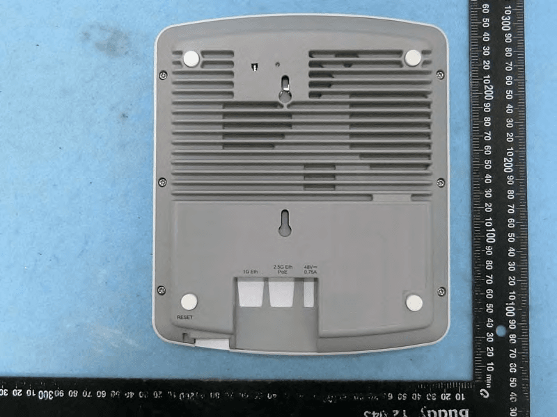
S9GR650P
Jul 11, 2021R650p Access Point
Equipment Class
DTS - Digital Transmission System
S9GR350
Jun 30, 2021Access Point
Equipment Class
NII - Unlicensed National Information Infrastructure TX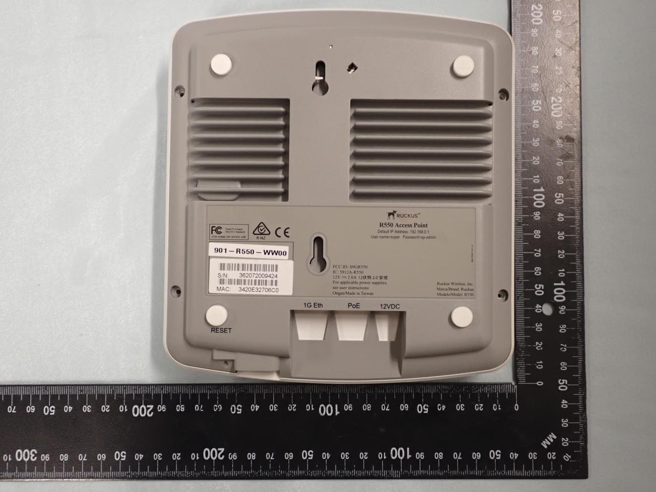
S9GR550P
Jun 30, 2021Wireless Access Point
Equipment Class
DTS - Digital Transmission System
S9GT350C
Mar 23, 2021Access point
Equipment Class
NII - Unlicensed National Information Infrastructure TX
S9GT350D
Mar 10, 2021Access point
Equipment Class
DTS - Digital Transmission System