S9GP300P300 Wireless Bridge
Ruckus Wireless, Inc.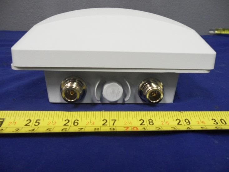
Click to zoom
Application Details
- Equipment Class
- NII - Unlicensed National Information Infrastructure TX
- Date of Grant
- Jun 07, 2015
- Application Purpose
- Original Equipment
- Date of Application
- Jun 07, 2015
- Equipment Note
- P300 Wireless Bridge
- Frequency Range
- 5745.00000000 - 5825.00000000
- Company
- Ruckus Wireless, Inc.
- Country
- United States
Documents & Files
Document Text
Text extracted from the exhibit documents filed with the FCC. Open a document above to read the original.
Users Manual
Page 1 Federal Communications Commission Notices This product complies with Part 15 of the FCC Rules. Operation is subject to the following two conditions: (1) this device may not cause harmful interference, and (2) this device must accept any interference received, including interference that may cause undesired operation. Caution: Changes or modifications to this equipment that have not been approved by Ruckus Wireless may void the user's authority to operate this equipment. Note: This equipment has been tested and found to comply with the limits for a Class B digital device, pursuant to part 15 of the FCC Rules. These limits are designed to provide reasonable protection against harmful interference in a residential installation. This equipment generates, uses and can radiate radio frequency energy and, if not installed and used in accordance with the instructions, may cause harmful interference to radio communications. However, there is no guarantee that interference will not occur in a particular installation. If this equipment does cause harmful interference to radio or television reception, which can be determined by turning the equipment off and on, the user is encouraged to try to correct the interference by one or more of the following measures: —Reorient or relocate the receiving antenna. —Increase the separation between the equipment and receiver. —Connect the equipment into an outlet on a circuit different from that to which the receiver is connected. —Consult the dealer or an experienced radio/TV technician for help. Industry Canada Statement Under Industry Canada regulations, this radio transmitter may only operate using an antenna of a type and maximum (or lesser) gain approved for the transmitter by Industry Canada. To reduce potential radio interference to other users, the antenna type and its gain should be so chosen that the equivalent isotropically radiated power (e.i.r.p.) is not more than that necessary for successful communication. Conformément à la réglementation d'Industrie Canada, le présent émetteur radio peut fonctionner avec une antenne d'un type et d'un gain maximal (ou inférieur) approuvé pour l'émetteur par Industrie Canada. Dans le but de réduire les risques de brouillage radioélectrique à l'intention des autres utilisateurs, il faut choisir le type d'antenne et son gain de sorte que la puissance isotrope rayonnée équivalente (p.i.r.e.) ne dépasse pas l'intensité nécessaire à l'établissement d'une communication satisfaisante. This device complies with Industry Canada licence-exempt RSS standard(s). Operation is subject to the following two conditions: (1) this device may not cause interference, and (2) this device must accept any interference, including interference that may cause undesired operation of the device. Le présent appareil est conforme aux CNR d'Industrie Canada applicables aux appareils radio exempts de licence. L'exploitation est autorisée aux deux conditions suivantes : (1) l'appareil ne doit pas produire de brouillage, et (2) l'utilisateur de l'appareil doit accepter tout brouillage radioélectrique subi, même si le brouillage est susceptible d'en compromettre le fonctionnement. The device for operation in the band 5150-5250 MHz is only for indoor use to reduce the potential for harmful interference to co-channel mobile satellite systems; the maximum antenna gain permitted for devices in the bands 5250-5350 MHz and 5470-5725 MHz shall comply with the e.i.r.p. limit; and the maximum antenna gain permitted for devices in the band 5725-5825 MHz shall comply with the e.i.r.p. limits specified for point-to-point and non point-to-point operation as appropriate. Le dispositif de fonctionnement dans la bande 5150-5250 MHz est réservé à une utilisation en intérieur pour réduire le risque d'interférences nuisibles à la co-canal systèmes mobiles par satellite, le gain d'antenne maximal autorisé pour les appareils dans les bandes 5250-5350 MHz et 5470-5725 MHz doit se conformer à la pire limite, et le gain d'antenne maximal autorisé pour les appareils dans la bande 5725-5825 MHz doivent être conformes avec le pire limites spécifiées à point-à-ponctuelles et non point-à-point de fonctionnement selon qu'il convient. Operation in the 5600-5650 MHz band is not allowed in Canada. High-power radars are allocated as primary users (i.e. priority users) of the bands 5250-5350 MHz and 5650-5850 MHz and that these radars could cause interference and/or damage to LE-LAN devices. Opération dans la bande 5600-5650 MHz n'est pas autorisée au Canada. Haute puissance radars sont désignés comme utilisateurs principaux (c. -à- utilisateurs prioritaires) des bandes 5250-5350 MHz et 5650-5850 MHz et que ces radars pourraient causer des interférences et / ou des dommages à dispositifs LAN-EL. Radiation Exposure Statement The device has been found to be compliant to the requirements set forth in CFR 47 Sections 2.1091 and Industry Canada RSS-102 for an uncontrolled environment. The antenna(s) used for this transmitter must be installed to provide a separation distance of at least 50 cm from all persons and must not be co-located or operating in conjunction with any other antenna or transmitter. Le dispositif a été jugé conforme aux exigences énoncées dans les articles 47 CFR 2.1091 et Industrie Canada RSS-102 pour un environnement non contrôlé. L'antenne (s) utilisée pour ce transmetteur doit être installé pour fournir une distance de séparation d'au moins 50 cm de toutes les personnes et ne doit pas être co-localisés ou fonctionner en conjonction avec une autre antenne ou transmetteur. Mexico Statement “La operación de este equipo está sujeta a las siguientes dos condiciones: (1) es posible que este equipo o dispositivo no cause interferencia perjudicial y (2) este equipo o dispositivo debe aceptar cualquier interferencia, incluyendo la que pueda causar su operación no deseada.” Page 2 Professionally Installed Products The product is to be installed according to the install…
Text truncated - open the document above for the full version.
Users Manual
Copyright © 2015 Ruckus Wireless, Inc.Published 26 May 2015, Part Number 800-70607-001 Rev A Page 1 of 4 START HERE P300 Wireless Bridge Quick Setup Guide This Installation Guide provides inf ormation on how to configure the Ruckus Wireless ZoneFlex P300 802. 11ac point-to-multipoint outdoor wireless bridge on the network. The P300 can use its internal 5GHz antennas, or can optionally use a tw o-port customer-ordered external 5GHz antenna. After completing the st eps described in this Guide, you will be able to place the P300 at your site. The rest of this guide refers to the P300 wireless bridge as the P300 . The P300 can be ordered either as an unconfigured single P300, or as a pre-configured matched pair of P3 00s. These P300s are almost always installed in pairs, whether they are configured as a Root Access Point (RAP) or reMote Access Point (MAP).Figure 1. P300s deployed as RAP and MAPNote: When deployed in the RAP--MAP_ _RAP--MAP config uration, the two wireless links must use different SSIDs. This Guide in Other Languages请从以下网站获得该指南的简体中文版 https://support.ruckuswireless.com Vous trouverez la version française de ce guide à l'adresse suivante https://support.ruckuswireless.com このガイドの日本語版は https://support.ruc kuswireless.com でご覧ください 이 가이드의 한국어 버전은 웹 사이트 ( https://support.ruc kuswireless.com ) 에서 확인하시기 바랍니다 Veja a versão em português (Brasil) deste guia em https://support.ruckuswireless.com Puede ver la versión en español (América Latina) de esta guía en https://support.ruckuswireless.com Before You BeginBefore deploying Ruckus Wireless prod ucts, please check for the latest software and the release documentation.• User Guides and Release Notes are available at http://support.ruckusw ireless.com/documents • Software Upgrades are available athttp://support.ruckusw ireless.com/software • Open Source information is available athttp://opensource. ruckuswireless.com • Software License and Limited Warranty are available at http://support.ruckusw ireless.com/warranty Safety Warnings• WARNING! Only trained and qualified pe rsonnel should be allowed to install, replace, or service this equip ment. The professional installer is responsible for the proper installati on and configuration of this P300. The P300 installation must comply wi th local regulatory requirements, especially with those regulating op eration near military and/or weather radar systems. • WARNING! Installation of this equipment must comply with local and national electrical codes. • WARNING! Ruckus Wireless strongly recommends that you wear eye protection before mounting the P300. • WARNING! The Ruckus Wireless PoE injector (ordered separately) is for indoor use only. Never mount th e PoE injector outdoors with the P300. • CAUTION: Make sure that you form a 80mm - 130mm (3”-5”) drip loop in any cable that is attached to the P300 or the building. This will prevent water from running along the cable and entering the P300 or the building where the cable terminates. • CAUTION: Be sure that grounding is available and that it meets local and national electrical codes. For additional lightning protection, use lightning rods and lightning arrestors. • NOTE: Allowable external antenna types and antenna gains may be limited by local regulatory requirements. Package ContentsBefore configuring or deploying your P300, verify that all items listed below are included in the package. If any item is damaged or missing, notify your authorized Ruckus Wireless sales representative. One or two P300 kits, depending on ordered part: • 901-P300-xx01, P300, 802.11ac 5GHz point-to-point wireless bridge, includes one P300 kit • 901-P300-xx02, P300, 802.11ac 5GHz point-to-point wireless bridge, pre-provisioned pair, includes two P300 kitswhere ‘xx’ is a country-specific code. Each P300 kit contains:• One P300, which includes a 12mm stainless steel M6x1 Phillips earth ground screw with split lock and flat washers (A in Figure 2 ) • One M25 data cable gland (B in Figure 2 ) • One green/yellow earth ground wire with ring terminal (C in Figure 2 ) • One wall- or pole-m ounting bracket (D in Figure 2 ) • One U-joint bracket (E in Figure 2 ) • One linkage bracket with two serrat ed external-tooth lock washers (F in Figure 2 ) • One P300 bracket (G in Figure 2 ) • Two sets 50mm stainless steel M8x1.2 5 hex bolt with split lock and flat washers (H in Figure 2 ) • Four SAE32-sized stainless steel cl amps, 38.1mm to 63.5mm (1.5" to 2.5") inner diameter (I in Figure 2 ) • Eight sets stainless steel 0.5-inch x 0.250-28 hex bolt with split lock and flat washers (J in Figure 2 ) • Four sets stainless steel 8mm M4x0 .7 pan head Phillips screws with split lock and flat washers (not shown, and not used) • Service Level Agreement/ Limited Warranty Statement • Regulatory Statement • Declaration of Conformity, if required • This Quick Setup Guide •The P300 Wireless Bridge Mounting Guide • N-Type Connector Sealing Instructions NOTE: This kit may include extra screws, nuts and washers. You may use the extras wherever required.Figure 2. P300 field-inst allation ki t contents LEDs and IndicationsThe P300 has five LEDs visible on th e outside of the chassis. The LEDs have different operating modes, and which can be manually turned on and off by the operator. Refer to Table 1 for a description of these LEDs and their operating modes. Note: The minimum software revision fo r the P300 is base image 100.0.1.9 or later. FlexMaster requ ires firmware 9.12 and later to manage the P300. MAP MAP RAP RAP MAP Table 1. P300 LED indications LED Normal Mode Aiming Mode (all green) AIM • Green = aiming mode • Off = normal mode • Green = aiming mode• Off = normal operation mode 5G • Off = radio down• Solid green = radio up & link up • Flashing green = radio up but no link Aiming Strength 1• Solid: RSSI >= Configured Minimum (28 > RSSI >= 20) • Blinking: RSSI < Configured Min (Default: 20, which is configurable) ROOT • Off = non root bridge • Solid green = root bridge Aiming Strength 2• Solid: …
Text truncated - open the document above for the full version.
Cover Letter(s)
05/7/2015 To: Federal Communications Commission Authorization and Evaluation Division 7435 Oakland Mills Road Columbia, MD Subject: DFS Channels for FCC ID: S9GP300 Ruckus Wireless, Inc. hereby declares that the device FCC IS: S9GP300 will not operate outside the bands of approval. Operation on DFS bands is disabled for initial DTS and NII approval. A Class Two Permissive Change (CLIIPC) will be pursued to gain approval in the DFS bands. Operation on DFS bands will remain disabled until approved by the FCC. Sincerely, Clinton Bradley / Compliance Engineer 350 West Java Drive, Sunnyvale, CA 94089 [email protected] / 408-636-4368
Cover Letter(s)
05/29/2015 To: Federal Communications Commission Authorization and Evaluation Division 7435 Oakland Mills Road Columbia, MD Subject: DFS Channels for FCC ID: S9GP300 Ruckus Wireless, Inc. hereby declares that the device FCC ID: S9GP300 will only be sold and operated as a point to point device until point to multipoint operation has been approved by the FCC. Sincerely, Clinton Bradley / Compliance Engineer 350 West Java Drive, Sunnyvale, CA 94089 [email protected] / 408-636-4368
Cover Letter(s)
5/8/2015 To: Federal Communications Commission Authorization and Evaluation Division 7435 Oakland Mills Road Columbia, MD Subject: Professional Installation for FCC ID: S9GP300 Ruckus Wireless, Inc. hereby declares that the device FCC ID: S9GP300 will only be installed by a professional installer. The product is only sold through Authorized Partners. The P300 is not for sale to the general public. Professional installation is guaranteed based on the use of only Authorized Partners and distribution channels. Professional training and support is provided as part of the Authorized Partner programs. Sincerely, Clinton Bradley / Compliance Engineer 350 West Java Drive, Sunnyvale, CA 94089 [email protected] / 408-636-4368
Cover Letter(s)
775 Montague Expressway Milpitas, CA 95035 Tel: 408-526-1188 Fax: 408-526-1088 Email: [email protected] Confidentiality Request Letter Reason for Amendment (current / obsolete) Revision History Approved Date From To Initial Release (obsolete) 1.0 1.0 Nov-14-2006 Adding CFR 2.459 (obsolete) 1.0 2.0 August – 11 - 2008 Updated company template & Added text box (current) 2.0 3.0 Jan-31-2012 SCS-F19: Confidentiality Request Letter Page 2 of 2 Rev 3.0 05/07/2015 To: Federal Communications Commission Authorization and Evaluation Division 7435 Oakland Mills Road Columbia, MD Subject: Permanent Confidentiality Request for FCC ID: S9GP300 We hereby request confidential treatment of information accompanying this application as outlined below: - Block Diagram [ P300 Block Diagram.pdf] - Schematics [ P300 Schematic.pdf] - Operational Description [P300 Radio Theory of Operation.pdf] -. Software Security Description The above materials contain trade secrets and proprietary information not customarily released to the public. The public disclosure of these materials may be harmful to the applicant and provide unjustified benefits to its competitors. The applicant understands that pursuant to Section 0.457 & 0.459 of the Rules, disclosure of this application and all accompanying documentation will not be made before the date of the Grant for this application. Sincerely, Clinton Bradley / Compliance Engineer 350 West Java Drive, Sunnyvale, CA 94089 [email protected] / 408-636 -4368
Cover Letter(s)
775 Montague Expressway Milpitas, CA 95035 Tel: 408-526-1188 Fax: 408-526-1088 Email: [email protected] Project and Product Certification Representative Authorization Letter Reason for Amendment (current / obsolete) Revision History Approved Date From To Initial Release (obsolete) 1.0 1.0 Nov-14-2006 Revised wording (obsolete) 1.0 2.0 Sept–25-2007 Updated company template (obsolete) 2.0 3.0 Jan-31-2012 Updated letter information (obsolete) 3.0 4.0 May-23-2014 Added FCC ID field (current) 4.0 5.0 Sept 16 2014 SCS-F18: Project and Product Certification Representative Authorization Letter Page 2 of 2 Rev 5.0 05/7/2015 To: SIEMIC, Inc. 775 Montague Expressway, Milpitas, CA 95035 USA Dear Sir/Madam, Re: Project and Product Certification Representative Authorization Letter We, Ruckus Wireless, Inc., hereby authorize SIEMIC, Inc. to act as Certification Body for certifying for the following project(s): FCC ID: S9GP300 Product Description: P300 Wireless Bridge Model: P300 We affirm that between SIEMIC, Inc. and Ruckus Wireless, Inc., any difference in understanding, including test plan, measurement methods, applicable standards and relevant procedures and processes have been resolved prior to commencement of testing activities. Sincerely, Clinton Bradley / Compliance Engineer 350 West Java Drive, Sunnyvale, CA 94089 [email protected] / 408-636-4368
Cover Letter(s)
775 Montague Expressway, Milpitas, CA 95035, USA Tel: +1(408) 526 1188, Fax: +1(408) 526 1088, Email: [email protected], URL: www.siemic.com July 07, 2015 To: FCC From: SIEMIC, INC. RE: Applicant: Ruckus Wireless, Inc., FCC ID: S9GP300, Request to supercede Test Report. There was a typo on the Test Report. The correction to the Test Report is antenna gain 13dBi to 14 dBi. The newly uploaded Test Report has the correction to 14 dBi. Thank you, Eileen Yang SIEMIC, INC. 775 Montague Expressway Milpitas, CA 95035 Tel: 408-526-1188 Fax: 408-526-1088
External Photos
EUT Photos - External Top View Bottom View Front View Rear View Left Side View Right Side View 21dBi Antenna 24dBi Antenna
ID Label/Location Info
Label & Location Label Location
Internal Photos
EUT Photos - Internal Cover Off View Main Board Top View Main Board Bottom View Shielding Off View I/O Board Top View I/O Board Bottom View 21dBi Antenna 24dBi Antenna
RF Exposure Info
MPE CALCULATION FCC ID: S9GP300 RF Exposure Requirements: 47 CFR §1.1307(b) RF Radiation Exposure Limits: 47 CFR §1.1310 RF Radiation Exposure Guidelines: FCC OST/OET Bulletin Number 65 EUT Frequency Band: 5180 – 5240 MHz, 5745 - 5825MHz Limits for General Population/Uncontrolled Exposure in the band of: 1500 - 100,000 MHz Power Density Limit: 1 mW / cm 2 Equation: S = PG / 4R 2 or R = √PG / 4S Where, S = Power Density P = Power Input to Antenna G = Antenna Gain R = distance to the center of radiated antenna ______________________________________________________________________________________________________________________ Prediction distance 50cm EUT: P300 (UNII Band): Power = 19.11dBm, Antenna Gain = 24 dBi, Power density = 0.65 mW/ cm 2 The Above Result had shown that the Device complied with MPE requirement. Completed By: Ricky Wang SIEMIC, Inc. 775 Montague Expressway, Milpitas, CA 95035 Date: Jun 1th, 2015
Test Report
775 Montague Expressway, Milpitas, CA 95035, USA • Phone: (+1) 408 526 1188 • Facsimile (+1) 408 526 1088 Visit us at: www.siemic.com; Follow us at: Report No.: FCC_RF_SL14091001-RUC-017_UNII REV3.1 Supersede Report No.: FCC_RF_SL14091001-RUC-017_UNII REV3.0 Applicant : Ruckus Wireless, Inc. Product Name : Wireless Bridge Model No. : P300 Test Standard : 47 CFR 15.407 Test Method : ANSI C63.10: 2013 789033 D02 General UNII Test Procedures New Rules v01 FCC ID : S9GP300 IC ID : 5912A-P300 Dates of test : 04/06/2015 to 04/20/2015 Issue Date : 07/06/2015 Test Result : ☒ Pass ☐ Fail Equipment complied with the specification [X] Equipment did not comply with the specification [ ] This Test Report is Issued Under the Authority of: Ricky Wang David Zhang Test Engineer Engineer Reviewer This test report may be reproduced in full only Test result presented in this test report is applicable to the tested sample only Issued By: SIEMIC Laboratories 775 Montague Expressway, Milpitas, 95035 CA RF TEST REPORT Test report No. FCC_RF_SL14091001-RUC-017_UNII REV3.1 Page 2 of 73 775 Montague Expressway, Milpitas, CA 95035, USA • Phone: (+1) 408 526 1188 • Facsimile (+1) 408 526 1088 Visit us at: www.siemic.com; Follow us at: Laboratory Introduction SIEMIC, headquartered in the heart of Silicon Valley, with superior facilities in US and Asia, is one of the leading independent testing and certification facilities providing customers with one-stop shop services for Compliance Testing and Global Certifications. In addition to testing and certification, SIEMIC provides initial design reviews and compliance management throughout a project. Our extensive experience with China, Asia Pacific, North America, European, and International compliance requirements, assures the fastest, most cost effective way to attain regulatory compliance for the global markets. Accreditations for Conformity Assessment Country/Region Accreditation Body Scope USA FCC, A2LA EMC, RF/Wireless, Telecom Canada IC, A2LA, NIST EMC, RF/Wireless, Telecom Taiwan BSMI, NCC, NIST EMC, RF, Telecom, Safety Hong Kong OFTA, NIST RF/Wireless, Telecom Australia NATA, NIST EMC, RF, Telecom, Safety Korea KCC/RRA, NIST EMI, EMS, RF, Telecom, Safety Japan VCCI, JATE, TELEC, RFT EMI, RF/Wireless, Telecom Mexico NOM, COFETEL, Caniety Safety, EMC, RF/Wireless, Telecom Europe A2LA, NIST EMC, RF, Telecom, Safety Israel MOC, NIST EMC, RF, Telecom, Safety Accreditations for Product Certifications Country Accreditation Body Scope USA FCC TCB, NIST EMC, RF, Telecom Canada IC FCB, NIST EMC, RF, Telecom Singapore iDA, NIST EMC, RF, Telecom EU NB EMC & R&TTE Directive Japan MIC (RCB 208) RF, Telecom Hong Kong OFTA (US002) RF, Telecom Test report No. FCC_RF_SL14091001-RUC-017_UNII REV3.1 Page 3 of 73 775 Montague Expressway, Milpitas, CA 95035, USA • Phone: (+1) 408 526 1188 • Facsimile (+1) 408 526 1088 Visit us at: www.siemic.com; Follow us at: CONTENTS 1 REPORT REVISION HISTORY ....................................................................................................................................... 4 2 EXECUTIVE SUMMARY ................................................................................................................................................. 5 3 CUSTOMER INFORMATION .......................................................................................................................................... 5 4 TEST SITE INFORMATION ............................................................................................................................................ 5 5 MODIFICATION ............................................................................................................................................................. 5 6 EUT INFORMATION ...................................................................................................................................................... 6 6.1 EUT Description ........................................................................................................................................................ 6 6.2 Radio Description ...................................................................................................................................................... 6 7 SUPPORTING EQUIPMENT/SOFTWARE AND CABLING DESCRIPTION ......................................................................... 8 7.1 Supporting Equipment ............................................................................................................................................... 8 7.2 Cabling Description ................................................................................................................................................... 8 7.3 Test Software Description .......................................................................................................................................... 8 8 TEST SUMMARY ........................................................................................................................................................... 9 9 MEASUREMENT UNCERTAINTY ................................................................................................................................. 10 10 MEASUREMENTS, EXAMINATION AND DERIVED RESULTS .................................................................................. 11 10.1 Conducted Emissions .......................................................................................................................................... 11 10.2 26 dB Bandwidth & 6 dB Bandwidth ...................................................................................................................... 14 10.3 Peak Output Power ............................................................................................................................................. 22 10.4 Peak Spectral Density ...............................................................................…
Text truncated - open the document above for the full version.
Test Report
Test report No. FCC_RF_SL14091001-RUC-017_UNII REV3.1 Page 37 of 73 775 Montague Expressway, Milpitas, CA 95035, USA • Phone: (+1) 408 526 1188 • Facsimile (+1) 408 526 1088 Visit us at: www.siemic.com; Follow us at: 14dBi ANT-PSD-802.11a-5745M-chain1 14dBi ANT-PSD-802.11a-5745M-chain2 14dBi ANT-PSD-802.11a-5785M-chain1 14dBi ANT-PSD-802.11a-5785M-chain2 14dBi ANT-PSD-802.11a-5825M-chain1 14dBi ANT-PSD-802.11a-5825M-chain2 Test report No. FCC_RF_SL14091001-RUC-017_UNII REV3.1 Page 38 of 73 775 Montague Expressway, Milpitas, CA 95035, USA • Phone: (+1) 408 526 1188 • Facsimile (+1) 408 526 1088 Visit us at: www.siemic.com; Follow us at: 14dBi ANT-PSD-802.11n-HT20-5745M-chain1 14dBi ANT-PSD-802.11n-HT20-5745M-chain2 14dBi ANT-PSD-802.11n-HT20-5785M-chain1 14dBi ANT-PSD-802.11n-HT20-5785M-chain2 14dBi ANT-PSD-802.11n-HT20-5825M-chain1 14dBi ANT-PSD-802.11n-HT20-5825M-chain2 Test report No. FCC_RF_SL14091001-RUC-017_UNII REV3.1 Page 39 of 73 775 Montague Expressway, Milpitas, CA 95035, USA • Phone: (+1) 408 526 1188 • Facsimile (+1) 408 526 1088 Visit us at: www.siemic.com; Follow us at: 14dBi ANT-PSD-802.11n-HT40-5755M-chain1 14dBi ANT-PSD-802.11n-HT40-5755M-chain2 14dBi ANT-PSD-802.11n-HT40-5795M-chain1 14dBi ANT-PSD-802.11n-HT40-5795M-chain2 14dBi ANT-PSD-802.11ac -5775M-chain1 14dBi ANT-PSD-802.11ac -5775M-chain2 Test report No. FCC_RF_SL14091001-RUC-017_UNII REV3.1 Page 40 of 73 775 Montague Expressway, Milpitas, CA 95035, USA • Phone: (+1) 408 526 1188 • Facsimile (+1) 408 526 1088 Visit us at: www.siemic.com; Follow us at: 21dBi ANT-PSD-802.11a-5745M-chain1 21dBi ANT-PSD-802.11a-5745M-chain2 21dBi ANT-PSD-802.11a-5785M-chain1 21dBi ANT-PSD-802.11a-5785M-chain2 21dBi ANT-PSD-802.11a-5825M-chain1 21dBi ANT-PSD-802.11a-5825M-chain2 Test report No. FCC_RF_SL14091001-RUC-017_UNII REV3.1 Page 41 of 73 775 Montague Expressway, Milpitas, CA 95035, USA • Phone: (+1) 408 526 1188 • Facsimile (+1) 408 526 1088 Visit us at: www.siemic.com; Follow us at: 21dBi ANT-PSD-802.11n-HT20-5745M-chain1 21dBi ANT-PSD-802.11n-HT20-5745M-chain2 21dBi ANT-PSD-802.11n-HT20-5785M-chain1 21dBi ANT-PSD-802.11n-HT20-5785M-chain2 21dBi ANT-PSD-802.11n-HT20-5825M-chain1 21dBi ANT-PSD-802.11n-HT20-5825M-chain2 Test report No. FCC_RF_SL14091001-RUC-017_UNII REV3.1 Page 42 of 73 775 Montague Expressway, Milpitas, CA 95035, USA • Phone: (+1) 408 526 1188 • Facsimile (+1) 408 526 1088 Visit us at: www.siemic.com; Follow us at: 21dBi ANT-PSD-802.11n-HT40-5755M-chain1 21dBi ANT-PSD-802.11n-HT40-5755M-chain2 21dBi ANT-PSD-802.11n-HT40-5795M-chain1 21dBi ANT-PSD-802.11n-HT40-5795M-chain2 21dBi ANT-PSD-802.11ac -5775M-chain1 21dBi ANT-PSD-802.11ac -5775M-chain2 Test report No. FCC_RF_SL14091001-RUC-017_UNII REV3.1 Page 43 of 73 775 Montague Expressway, Milpitas, CA 95035, USA • Phone: (+1) 408 526 1188 • Facsimile (+1) 408 526 1088 Visit us at: www.siemic.com; Follow us at: 24dBi ANT-PSD-802.11a-5745M-chain1 24dBi ANT-PSD-802.11a-5745M-chain2 24dBi ANT-PSD-802.11a-5785M-chain1 24dBi ANT-PSD-802.11a-5785M-chain2 24dBi ANT-PSD-802.11a-5825M-chain1 24dBi ANT-PSD-802.11a-5825M-chain2 Test report No. FCC_RF_SL14091001-RUC-017_UNII REV3.1 Page 44 of 73 775 Montague Expressway, Milpitas, CA 95035, USA • Phone: (+1) 408 526 1188 • Facsimile (+1) 408 526 1088 Visit us at: www.siemic.com; Follow us at: 24dBi ANT-PSD-802.11n-HT20-5745M-chain1 24dBi ANT-PSD-802.11n-HT20-5745M-chain2 24dBi ANT-PSD-802.11n-HT20-5785M-chain1 24dBi ANT-PSD-802.11n-HT20-5785M-chain2 24dBi ANT-PSD-802.11n-HT20-5825M-chain1 24dBi ANT-PSD-802.11n-HT20-5825M-chain2 Test report No. FCC_RF_SL14091001-RUC-017_UNII REV3.1 Page 45 of 73 775 Montague Expressway, Milpitas, CA 95035, USA • Phone: (+1) 408 526 1188 • Facsimile (+1) 408 526 1088 Visit us at: www.siemic.com; Follow us at: 24dBi ANT-PSD-802.11n-HT40-5755M-chain1 24dBi ANT-PSD-802.11n-HT40-5755M-chain2 24dBi ANT-PSD-802.11n-HT40-5795M-chain1 24dBi ANT-PSD-802.11n-HT40-5795M-chain2 24dBi ANT-PSD-802.11ac -5775M-chain1 24dBi ANT-PSD-802.11ac -5775M-chain2 Test report No. FCC_RF_SL14091001-RUC-017_UNII REV3.1 Page 46 of 73 775 Montague Expressway, Milpitas, CA 95035, USA • Phone: (+1) 408 526 1188 • Facsimile (+1) 408 526 1088 Visit us at: www.siemic.com; Follow us at: 10.5 Radiated Emissions below 1GHz Requirement(s): Spec Requirement Applicable 47CFR§ 15.407(b) 15.209 (a) Except higher limit as specified elsewhere in other section, the emissions from the low- power radio-frequency devices shall not exceed the field strength levels specified in the following table and the level of any unwanted emissions shall not exceed the level of the fundamental emission. The tighter limit applies at the band edges Frequency range (MHz) Field Strength (uV/m) 30 – 88 100 88 – 216 150 216 960 200 Above 960 500 ☒ Test Setup Procedure 1. The EUT was switched on and allowed to warm up to its normal operating condition. 2. The test was carried out at the selected frequency points obtained from the EUT characterisation. Maximization of the emissions, was carried out by rotating the EUT, changing the antenna polarization, and adjusting the antenna height in the following manner: a. Vertical or horizontal polarisation (whichever gave the higher emission level over a full rotation of the EUT) was chosen. b. The EUT was then rotated to the direction that gave the maximum emission. c. Finally, the antenna height was adjusted to the height that gave the maximum emission. 3. A Quasi-…
Text truncated - open the document above for the full version.
Contact Information
Applicant
Ivaylo Tankov(Principal Wireless Compliance Engineering)
Test Firm
Bureau Veritas Consumer Products Services, Inc.Sarb Shelopal
[email protected]+1 925 963 4420
Technical Specifications
| # | Rule Parts | Frequency Range | Power Output |
|---|---|---|---|
| 2 | 15E | 5.75 GHz - 5.83 GHz | 76.00 mW |
Other Applications from Ruckus Wireless, Inc.
S9GR650P
Jul 11, 2021R650p Access Point
Equipment Class
DTS - Digital Transmission System
S9GR350
Jun 30, 2021Access Point
Equipment Class
NII - Unlicensed National Information Infrastructure TX
S9GR550P
Jun 30, 2021Wireless Access Point
Equipment Class
DTS - Digital Transmission System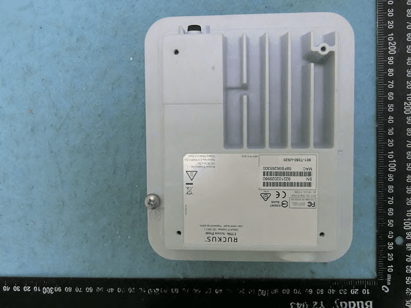
S9GT350C
Mar 23, 2021Access point
Equipment Class
NII - Unlicensed National Information Infrastructure TX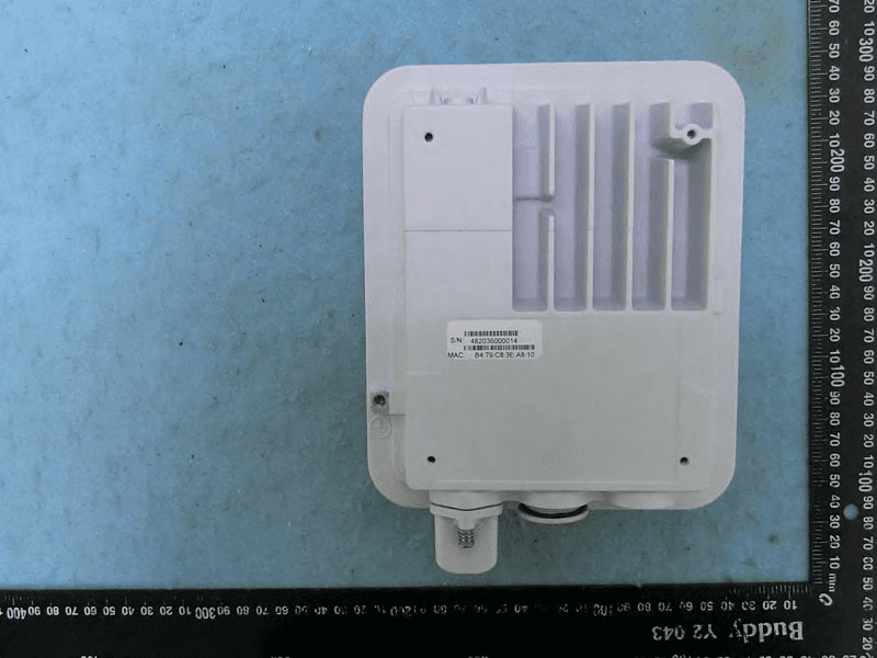
S9GT350D
Mar 10, 2021Access point
Equipment Class
DTS - Digital Transmission System