S9GR500IEEE 802.11ac Access Point
Ruckus Wireless, Inc.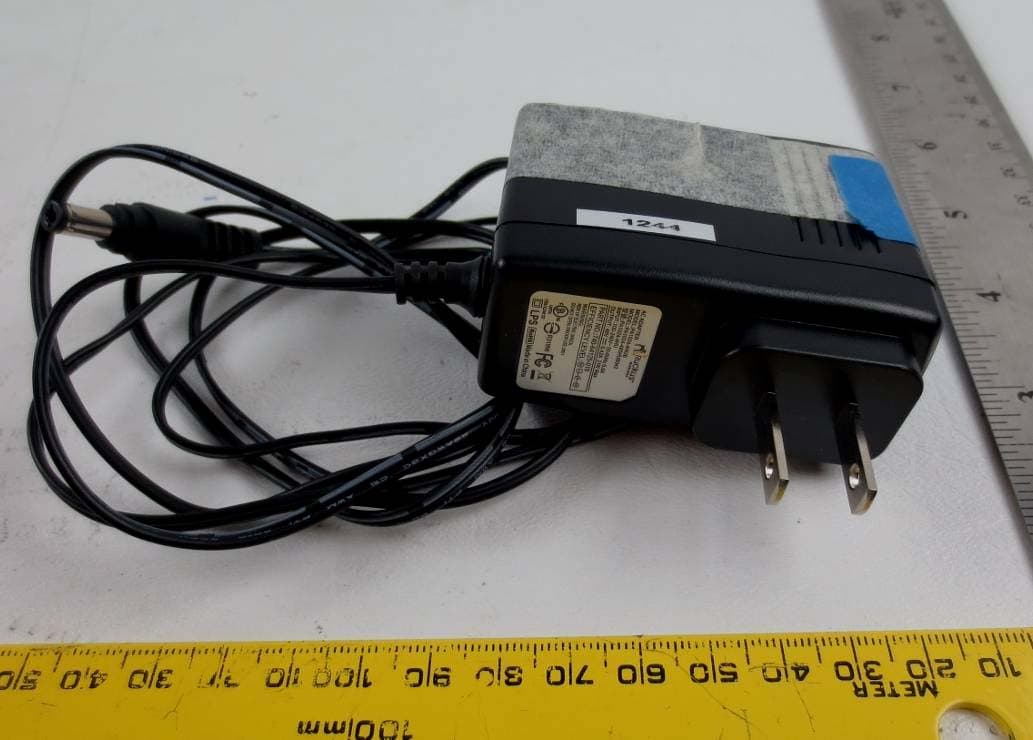
Click to zoom
Application Details
- Equipment Class
- NII - Unlicensed National Information Infrastructure TX
- Date of Grant
- Sep 01, 2014
- Application Purpose
- Original Equipment
- Date of Application
- Sep 01, 2014
- Equipment Note
- IEEE 802.11ac Access Point
- Frequency Range
- 5745.00000000 - 5825.00000000
- Company
- Ruckus Wireless, Inc.
- Country
- United States
Documents & Files
Document Text
Text extracted from the exhibit documents filed with the FCC. Open a document above to read the original.
Users Manual
Copyright © 2014 Ruckus Wireless, Inc. Page 1 of 4 Published July 2014, Part Number 800-70564-001 Rev A R500 Access Point Quick Setup Guide This Quick Setup Guide provides step-by-step instructions on how to set up your Ruckus Wireless R500 Dual Band 802.11ac Multimedia Wi-Fi A ccess Point. After completing the steps described in this Guid e, you will be able to place the Access Point (AP) at your site and provide wireless network access to users. B EFORE Y OU B EGIN Before deploying Ruckus Wireless products, please check for the latest software and the release documentation.• User Guides and Release Notes are available at http://support.ruckuswireless.com/documents . • Software Upgrades are available at http://support.ruckusw ireless.com/software . • Open Source information is available at http://opensource.ruckuswireless.com . • Software License and Limited Warranty are available at http://support.ruckusw ireless.com/warranty . P ACKAGE C ONTENTS • R500 Access Point • Two wall-mount anchor kits, including two 1" No. 8 steel panhead Phillips sheet metal screw screws, one 5mm M2.5 x 1.06 Torx security screw, and wall-mount anchors • One external T-bar bracket (two unassembled parts) • One unit removal pin • Regulatory flyer • Product warranty statement • Declaration of Conformity, if required •This Quick Setup Guide S TEP 1: C OLLECT T OOLS AND S ETUP R EQUIRE - MENTS• A computer running Windows 7 (procedures for other OS’s are similar) • Two Cat 5e Ethernet cables • No. 2 Phillips screwdriver and T8 Torx driver for wall mount-ing anchor kit • An AC power adapter (sold separately), or • An 802.3af or 802.3at -complia nt Power over Ethernet (PoE) switch or PoE injector S TEP 2: C ONNECT THE AP TO Y OUR C OMPUTER Figure 1: Top view1 After removing your Ruckus Wireless AP from its pack-age, place it next to your computer. 2 Using an Ethernet cable, co nnect your computer’s net- work port to one of the two ports on the AP. 3 Using an AC adapter (sold separately), connect the AP 12VDC port to a protected power source. Alternatively, connect the PoE port to a PoE injector or switch for both power and network connections. 4 Verify that the Power LED on the external enclosure is a steady green. Figure 2: Bottom view S TEP 3: P REPARE Y OUR C OMPUTER FOR AP S ETUP 1 On your Windows 7 computer, configure your network adapter from the Local Area Connection settings as fol- lows:• Start > Control Panel > Network and Sharing Center > Change Adapter Settings 2 Edit the TCP/IPv4 address settings as follows: • Local Area Connection > Properties > Internet Protocol Version 4 (TCP/IPv4) > Properties The TCP/IPv4 Properties dialog box appears. 3 Select Use the following IP address (if it is not already selected) and then make the following entries:• IP address : 192.168.0.22 (or any address in the 192.168.0.x network) • Subnet mask : 255.255.255.0 • Default gateway : 192.168.0.1 Leave the DNS server fields empty. 4 Click OK to save your changes. Your changes are put into effect immediately. S TEP 4: L OG I NTO THE AP As specified earlier, the AP should be directly connected to your computer (through one of the Ethernet ports) and powered on, ready for setup.1 On your computer, open a Web browser window. 2 In the browser, type this URL to connect to the AP: https://192.168.0.1 3 Press <Enter> to initiate the connection. When a secu- rity alert dialog box appears, click OK/Yes to proceed. 4 When the Ruckus Wireless Admin login page appears, enter the following: • Username : super • Password : sp-admin 5 Click Login . Note: The R500 requires a mini mum of ZoneFlex (ZF) firmware version 9.8.1 or later or SmartCell Gateway (SCG) firmware version 2.5.1 or later. IMPORTANT! If the AP is deployed with a ZoneDirector, then refer to the ZoneDirector Quick Setup Guide and connect the AP to your local network. PoE Port 12VDC Port Note: The following procedures assume Windows 7 as the operating system. Procedures for other OS’s are similar.Important! Write down all of the currently active settings so you can restore your computer to its current configuration later (when this process is complete). Copyright © 2014 Ruckus Wireless, Inc. Page 2 of 4 Published July 2014, Part Number 800-70564-001 Rev A S TEP 5: C USTOMIZE THE W IRELESS S ETTINGS 1 On the Web interface menu, click Configuration > Radio 2.4G or Configuration > Radio 5G . The Configure :: Wireless :: Common options appear. 2 Verify that the following options are active:• Channel : SmartSelect • Country Code : If you are not located in the United States, select your current country. 3 Click Update Settings if you made any changes. 4 Click any of the “Wireless #” tabs at the top of the page. 5 In Wireless Availability , click Enabled . 6 Delete the text in the SSID field, then type a name for your network that will help your users identify the AP in their wireless network connection application. 7 Click Update Settings to save your changes. 8 Repeat Steps 4-7 for each Wireless # interface that you want to enable. 9 Click Logout to exit the Web interface. 10 When the Ruckus Wireless Admin login page reappears, you can exit your browser. 11 Disconnect the AP from the computer and from the cur- rent power source, and then re store your computer to its original network connection configuration. S TEP 6: P LACE THE AP IN Y OUR S ITE 1 Move the AP to its permanen t location (accessible to both power and network connections). Refer to (Optional) Mounting Instructions for physical installation. 2 Use an Ethernet cable to connect the PoE port to the appropriate device:• The ISP’s or carrier’s network device • The Ethernet switch that is connected to the ISP’s or carrier’s network device 3 Connect the AP power adapter (or PoE power supply) to the AP, then to a convenient power source. 4 Verify that the PoE port LED is lit. After a short pause to re-establish the Internet connection, you can test the AP. S TEP 7: V ERIFY THE I NSTALLATION 1 Using any wireless-enabled co m…
Text truncated - open the document above for the full version.
Cover Letter(s)
350 West Java Drive TEL + .650.265.4200 Sunnyvale, CA 94089 USA FAX +.480.738.2065 www.ruckuswireless.com Date: July 25, 2014 To: Bay Area Compliance Laboratories Corp. 1274 Anvilwood Avenue Sunnyvale, CA 94089 Dear Sir/Madam, Re: Project and Product Certification Representative Authorization Letter We, Ruckus Wireless, Inc. has authorized Bay Area Compliance Laboratories Corp to act as a laboratory for testing and test report generation for the following project(s): Model: R500 FCC ID: S9GR500 We affirm that between BACL and Ruckus Wireless, Inc. any difference in understanding, including test plan, measurement methods, applicable standards and relevant procedures and processes have been resolved prior to commencement of testing activities. Sincerely, Clinton Bradley Compliance Engineer 1-408-636-4368 [email protected]
Cover Letter(s)
350 West Java Drive TEL + .650.265.4200 Sunnyvale, CA 94089 USA FAX +.480.738.2065 www.ruckuswireless.com 7/25/2014 Federal Communications Commission Equipment Authorization Branch 7435 Oakland Mills Road Columbia, MD 21046 Request for Confidentiality Company name: Ruckus Wireless, Inc. FCC ID: S9GR500 FCC Part 15 Certification Gentlemen, Pursuant to 47 CFR 0.457(d)(1)(ii) and 0.459 Ruckus Wireless, Inc. hereby requests permanent confidentiality of the following documents for the subject application: Exhibit Type File Name Description Schematics R500 Schematic.pdf Schematics Operational Description R500 Radio Description.pdf Radio Theory of Operation Block Diagram R500 Block Diagram.pdf Block Diagram Reason why the material should be withheld from public inspection: These documents contain detailed system, equipment description and related information about the product which Ruckus Wireless, Inc. considers to be proprietary, confidential, and a custom design otherwise not released to the general public. State why the information is a “trade secret;” Since the design is a basis from which future technological products will evolve, Ruckus Wireless, Inc. considers that this information would be of benefit to its competitors and that the disclosure of the information in these documents would give competitors an unfair advantage in the market. State whether the information is publicly available anywhere else: This information is not made publically available. Sincerely, Clinton Bradley Compliance Engineer
External Photos
Ruckus Wireless Inc FCC ID: S9GR500 Report Number: R1403241-407 Rev B Page 99 of 105 FCC Part 15.407 Test Report 15 Exhibit C – EUT Photographs 15.1 EUT Photo: Top View 15.2 EUT Photo: Bottom View Ruckus Wireless Inc FCC ID: S9GR500 Report Number: R1403241-407 Rev B Page 100 of 105 FCC Part 15.407 Test Report 15.3 EUT Photo: Front View 15.4 EUT Photo: Rear View Ruckus Wireless Inc FCC ID: S9GR500 Report Number: R1403241-407 Rev B Page 101 of 105 FCC Part 15.407 Test Report 15.5 DC Adaptor/POE View 15.6 AC Adaptor View
ID Label/Location Info
1. Replace “XXX” with the country of manufacture 2. Dielines/cutlines do not print 3. P/N 877-76405-001 Rev. A1 4. Colors: BLACK PMS 716C
Internal Photos
Ruckus Wireless Inc FCC ID: S9GR500 Report Number: R1403241-407 Rev B Page 102 of 105 FCC Part 15.407 Test Report 15.7 EUT Photo: Open Case View 15.8 PCB Main Board: Top View Ruckus Wireless Inc FCC ID: S9GR500 Report Number: R1403241-407 Rev B Page 103 of 105 FCC Part 15.407 Test Report 15.9 PCB Main Board: Bottom View 15.10 PCB Main Board without shielding: Top View Ruckus Wireless Inc FCC ID: S9GR500 Report Number: R1403241-407 Rev B Page 104 of 105 FCC Part 15.407 Test Report 15.11 PCB Main Board without shielding: Bottom View
RF Exposure Info
Ruckus Wireless Inc FCC ID: S9GR500 Report Number: R1403241-407 Rev B Page 11 of 105 FCC Part 15.407 Test Report 5 FCC §15.407 (f), §2.1091– RF Exposure 5.1 Applicable Standard According to FCC §15.407(f) and §1.1307(b)(1), systems operating under the provisions of this section shall be operated in a manner that ensures that the public is not exposed to radio frequency energy level in excess of the Commission’s guidelines. Limits for General Population/Uncontrolled Exposure Frequency Range (MHz) Electric Field Strength (V/m) Magnetic Field Strength (A/m) Power Density (mW/cm 2 ) Averaging Time (minutes) Limits for General Population/Uncontrolled Exposure 0.3-1.34 614 1.63 * (100) 30 1.34-30 824/f 2.19/f * (180/f 2 ) 30 30-300 27.5 0.073 0.2 30 300-1500 / / f/1500 30 1500-100,000 / / 1.0 30 f = frequency in MHz * = Plane-wave equivalent power density 5.2 MPE Prediction Predication of MPE limit at a given distance, Equation from OET Bulletin 65, Edition 97-01 S = PG/4R² Where: S = power density P = power input to antenna G = power gain of the antenna in the direction of interest relative to an isotropic radiator R = distance to the center of radiation of the antenna 5.3 MPE Results 5.2 GHz band: Maximum peak output power at antenna input terminal (dBm): 23.66 Maximum peak output power at antenna input terminal (mW): 232.2737 Prediction distance (cm): 20 Prediction frequency (MHz): 5240 Maximum Antenna Gain, typical (dBi): 3.0 Maximum Antenna Gain (numeric): 1.995 Power density of prediction frequency at 20.0 cm (mW/cm 2 ): 0.0922 MPE limit for uncontrolled exposure at prediction frequency (mW/cm 2 ): 1.0 Ruckus Wireless Inc FCC ID: S9GR500 Report Number: R1403241-407 Rev B Page 12 of 105 FCC Part 15.407 Test Report 5.8 GHz band: Maximum peak output power at antenna input terminal (dBm): 25.14 Maximum peak output power at antenna input terminal (mW): 326.5878 Prediction distance (cm): 20 Prediction frequency (MHz): 5785 Maximum Antenna Gain, typical (dBi): 3.0 Maximum Antenna Gain (numeric): 1.995 Power density of prediction frequency at 20.0 cm (mW/cm 2 ): 0.1296 MPE limit for uncontrolled exposure at prediction frequency (mW/cm 2 ): 1.0 2.4 GHz band: Maximum peak output power at antenna input terminal (dBm): 23.12 Maximum peak output power at antenna input terminal (mW): 205.1162 Prediction distance (cm): 20 Prediction frequency (MHz): 2437 Maximum Antenna Gain, typical (dBi): 1.0 Maximum Antenna Gain (numeric): 1.258 Power density of prediction frequency at 20.0 cm (mW/cm 2 ): 0.0513 MPE limit for uncontrolled exposure at prediction frequency (mW/cm 2 ): 1.0 The total exposure level of 2.4 GHz and 5.8 GHz band co-location at 20 cm distance is 0.1296+0.0513= 0.1809 mW/cm 2 which is less than limit of 1.0 mW/ cm 2 .
Test Setup Photos
Ruckus Wireless Inc FCC ID: S9GR500 Report Number: R1403241-407 Rev B Page 96 of 105 FCC Part 15.407 Test Report 14 Exhibit B - EUT Setup Photographs 14.1 Conducted Emissions - POE Powered Front View 14.2 Conducted Emissions POE Powered Side View Ruckus Wireless Inc FCC ID: S9GR500 Report Number: R1403241-407 Rev B Page 97 of 105 FCC Part 15.407 Test Report 14.3 Radiated Emission below 1 GHz Front View 14.4 Radiated Emission below 1 GHz Rear View Ruckus Wireless Inc FCC ID: S9GR500 Report Number: R1403241-407 Rev B Page 98 of 105 FCC Part 15.407 Test Report 14.5 Radiated Emission above 1 GHz Front View 14.6 Radiated Emission above 1 GHz Rear View
Contact Information
Applicant
Ivaylo Tankov(Principal Wireless Compliance Engineering)
Test Firm
Bay Area Compliance Laboratories Corp.Lisa Tang
Technical Specifications
| # | Rule Parts | Frequency Range | Power Output |
|---|---|---|---|
| 2 | 15E | 5.75 GHz - 5.83 GHz | 327.00 mW |
Other Applications from Ruckus Wireless, Inc.
S9GR650P
Jul 11, 2021R650p Access Point
Equipment Class
DTS - Digital Transmission System
S9GR350
Jun 30, 2021Access Point
Equipment Class
NII - Unlicensed National Information Infrastructure TX
S9GR550P
Jun 30, 2021Wireless Access Point
Equipment Class
DTS - Digital Transmission System
S9GT350C
Mar 23, 2021Access point
Equipment Class
NII - Unlicensed National Information Infrastructure TX
S9GT350D
Mar 10, 2021Access point
Equipment Class
DTS - Digital Transmission System