S9GR850Wireless Access Point
Ruckus Wireless, Inc.
Click to zoom
Application Details
- Equipment Class
- NII - Unlicensed National Information Infrastructure TX
- Date of Grant
- Apr 29, 2020
- Application Purpose
- Original Equipment
- Date of Application
- Apr 15, 2020
- Equipment Note
- Wireless Access Point
- Frequency Range
- 5745.00000000 - 5825.00000000
- Company
- Ruckus Wireless, Inc.
- Country
- United States
Documents & Files
Document Text
Text extracted from the exhibit documents filed with the FCC. Open a document above to read the original.
Users Manual
R850 Access Point Quick Setup Guide This Quick Setup Guide provides step-by-step instructions on how to install and begin using your Ruckus R850 Dual-Band 802.11ax Multimedia Wi-Fi Access Point (AP). After completing the steps described in this guide, you will be able to place the R850 at your site and begin providing wireless access to users. NOTE: AP R850 is supported in the following releases: •SmartZone (SZ) release 5.2 using New AP Model Patch •ZoneDirector (ZD) release 10.4.1 Native Support FIGURE 1 R850 - top This Guide in Other Languages •请从以下网站获得该指南的简体中文版 https:// support.ruckuswireless.com. •Vous trouverez la version française de ce guide à l'adresse suivante https://support.ruckuswireless.com. •このガイドの日本語版は https://support.ruckuswireless.com でご覧 ください。 •이 가이드의 한국어 버전은 웹 사이트 (https:// support.ruckuswireless.com) 에서 확인하시기 바랍니다. •Veja a versão em português (Brasil) deste guia em https:// support.ruckuswireless.com. •Puede ver la versión en español (América Latina) de esta guía en https://support.ruckuswireless.com. Before You Begin Before deploying Ruckus products, please check for the latest software and the release documentation. •Release Notes and other user documentation are available at http:// support.ruckuswireless.com/documents. •Software upgrades are available at http://support.ruckuswireless.com/ software. •Software license and limited warranty information are available at http://support.ruckuswireless.com/warranty. Package Contents A complete R850 installation package includes all of the items listed below: •R850 Access Point •One wall-mount anchor kit, including two 1-in. No. 8 steel pan head Phillips sheet metal screws and wall-mount anchors •One external T-bar bracket (two unassembled parts) •Service Level Agreement/Limited Warranty Statement •Declaration of Conformity •Regulatory Statement •Ruckus Access Point Getting Started Guide •AP Cloud Management Insert •This Quick Setup Guide Step 1: Collecting Setup Requirements, Hardware and Tools •Admin PC (computer with an Ethernet port and Wi-Fi adapter) •Cat 5e (or better) Ethernet cable •Ruckus Wireless 48VDC power adapter (sold separately) or 802.3at- compliant Power over Ethernet (PoE) switch or PoE injector NOTE: The PoE switch port must run link layer discovery protocol (LLDP) power over Ethernet/MDI (PoE+) in order for the R850 to operate in full-power mode. This may require enabling both LLDP and Power via MDI (dot3) on the switch, if available. NOTE: If powered by 802.3at PoE, note that the feature set is reduced, as follows: –4x4 (2.4GHz) + 4x4 (5GHz) chain operation mode (reduced from 4x4 (2.4GHz) + 8x8 (5GHz) under full power) NOTE: The recommended PoE injector for the R850 is GRT-480125A (60W power rating and 1 Gbps link speed). If using the recommended PoE injector, you must 1) manually select AT+ mode as the power mode in the SmartZone/ZoneDirector GUI, and 2) force 1Gbps link speed on the switch. Optional hardware and tools: •Customer-supplied small padlock with a 3.5-mm (0.14-in.) or smaller shackle diameter, used to fasten the AP to the secure mounting bracket or the T-bar bracket. •Customer-ordered Ruckus Wireless 902-0120-0000 secure mounting bracket kit: –If you are mounting the AP on a flat surface using the secure mounting bracket kit, then you need an electric drill with 4.75-mm (3/16-in.) drill bits. –If you are mounting the AP on a pipe or pole using the secure mounting bracket kit, then you will also need a 38.1-mm to 63.5-mm (1.5-in. to 2.5-in.) pipe or pole, two pole clamps, and hand tools to tighten the clamps. Step 2: Connecting Your Computer to the AP 1.Using an Ethernet cable, connect your computer’s network port to the 5G ETH PoE port on the AP (1 in the Figure below). 2.Using a DC power adapter (sold separately), connect the AP's 48 VDC port (2 in the Figure below) to a convenient and protected power source. NOTE: Alternatively, connect the 5G ETH PoE port to a PoE injector or switch for both power and network connectivity. FIGURE 2 AP Ports TABLE 1 R850 bottom panel elements No.LabelDescription 15G ETH PoE 100/1000/5000 Mbps PoE In Port: RJ-45 Ethernet port (supports 802.3at/at+ PoE in) 21G ETH10/100/1000 Mbps port: RJ-45 Ethernet port (non-PoE) 348 VDC48 VDC input 4USBUSB Port •Max Dimensions: 6 cm x 2 cm x 1.1 cm •Interface: USB 2.0 •Connector: USB – Type-A plug 3.Verify that the PWR LED on the AP is a steady green. Step 3: Preparing Your Computer for AP Setup NOTE: The following procedures assume Windows as the operating system. Procedures for other operating systems are similar. 1.On your Windows PC, configure your network adapter from the Local Area Connection settings as follows: Start > > Control Panel > Network and Sharing Center > Change Adapter Settings 2.Edit the TCP/IPv4 address settings as follows: Copyright © 2020 CommScope, Inc. All rights reserved.Page 1 of 4 Published April 2020, Part Number 800-72487-001 Rev B Local Area Connection > Properties > Internet Protocol Version 4 (TCP/IPv4) > Properties The Internet Protocol Version 4 (TCP/IPv4) Properties dialog box appears. IMPORTANT-QSG: Write down all of the currently active settings so you can restore your computer to its current configuration later (when this process is complete). 3.Select Use the following IP address (if it is not already selected) and then make the following entries: •IP address: 192.168.0.22 (or any available address in the 192.168.0.x network, except 192.168.0.1) •Subnet mask: 255.255.255.0 •Default gateway: 192.168.0.1 Leave the DNS server fields empty. 4.Click OK to save your changes. Your changes are put into effect immediately. Step 4: Logging Into the AP 1.As specified in Step 3, the admin PC should be directly connected to the AP through one of the Ethernet ports and powered on, ready for setup. 2.On your admin PC, open a web browser window. 3.In the browser, enter the following URL in the browser navigation bar: https://192.168.0.1 4.Press Enter to initiate the connection. When the security …
Text truncated - open the document above for the full version.
Users Manual
Page 1 Ruckus Wireless, Inc. 350 West Java Drive Sunnyvale, CA 94089 USA R850 – Indoor Enterprise AP Ruckus Wireless Inc., an ARRIS Company Federal Communications Commission Notices 350 W. Java Dr., Sunnyvale CA 94089 USA This product complies with Part 15 of the FCC Rules. Operation is subject to the following two conditions: (1) this device may not cause harmful interference, and (2) this device must accept any interference received, including interference that may cause undesired operation. Caution: Changes or modifications to this equipment that have not been approved by Ruckus Wireless may void the user's authority to operate this equipment. For Class B Equipment: Note: This equipment has been tested and found to comply with the limits for a Class B digital device, pursuant to part 15 of the FCC Rules. These limits are designed to provide reasonable protection against harmful interference in a residential installation. This equipment generates uses and can radiate radio frequency energy and, if not installed and used in accordance with the instructions, may cause harmful interference to radio communications. However, there is no guarantee that interference will not occur in a particular installation. If this equipment does cause harmful interference to radio or television reception, which can be determined by turning the equipment off and on, the user is encouraged to try to correct the interference by one or more of the following measures: — Reorient or relocate the receiving antenna. — Increase the separation between the equipment and receiver. — Connect the equipment into an outlet on a circuit different — Consult the dealer or an experienced radio/TV technician for help. from that to which the receiver is connected. This device meets all the other requirements specified in Part 15E, Section 15.407 of the FCC Rules. This transmitter must not be co-located or operating in conjunction with any other antenna or transmitter. Note: The country code selection is for non-US models only and is not available on US model. Per FCC regulation, Wireless product marketed in the US must be restricted to operate only on spectrum allocated per FCC Rules and Regulations. Radiation Exposure Statement: This equipment complies with FCC radiation exposure limits set forth for an uncontrolled environment. This equipment should be installed and operated with minimum distance 20 cm between the radiator & your body. Canada Statement Under ISED regulations, this radio transmitter may only operate using an antenna of a type and maximum (or lesser) gain approved for the transmitter by ISED. To reduce potential radio interference to other users, the antenna type and its gain should be so chosen that the equivalent isotropically radiated power (e.i.r.p.) is not more than that necessary for successful communication. Conformément à la réglementation d’ISED, le présent émetteur radio peut fonctionner avec une antenne d'un type et d'un gain maximal (ou inférieur) approuvé pour l'émetteur par ISED. Dans le but de réduire les risques de brouillage radioélectrique à l'intention des autres utilisateurs, il faut choisir le type d'antenne et son gain de sorte que la puissance isotrope rayonnée équivalente (p.i.r.e.) ne dépasse pas l'intensité nécessaire à l'établissement d'une communication satisfaisante. This device complies with ISED licence-exempt RSS standard(s). Operation is subject to the following two conditions: (1) this device may not cause interference, and (2) this device must accept any interference, including interference that may cause undesired operation of the device. Le présent appareil est conforme aux CNR d'ISED applicables aux appareils radio exempts de licence. L'exploitation est autorisée aux deux conditions suivantes : (1) l'appareil ne doit pas produire de brouillage, et (2) l'utilisateur de l'appareil doit accepter tout brouillage radioélectrique subi, même si le brouillage est susceptible d'en compromettre le fonctionnement. The device for operation in the band 5150-5250 MHz is only for indoor use to reduce the potential for harmful interference to co-channel mobile satellite systems; the maximum antenna gain permitted for devices in the bands 5250-5350 MHz and 5470-5725 MHz shall comply with the e.i.r.p. limit; and the maximum antenna gain permitted for devices in the band 5725-5825 MHz shall comply with the e.i.r.p. limits specified for point-to-point and non point- to-point operation as appropriate. Le dispositif de fonctionnement dans la bande 5150-5250 MHz est réservé à une utilisation en intérieur pour réduire le risque d'interférences nuisibles à la co-canal systèmes mobiles par satellite, le gain d'antenne maximal autorisé pour les appareils dans les bandes 5250-5350 MHz et 5470-5725 MHz doit se conformer à la pire limite, et le gain d'antenne maximal autorisé pour les appareils dans la bande 5725-5825 MHz doivent être conformes avec le pire limites spécifiées à point-à-ponctuelles et non point-à-point de fonctionnement selon qu'il convient. Operation in the 5600-5650 MHz band is not allowed in Canada. High-power radars are allocated as primary users (i.e. priority users) of the bands 5250-5350 MHz and 5650-5850 MHz and that these radars could cause interference and/or damage to LE-LAN devices. Opération dans la bande 5600-5650 MHz n'est pas autorisée au Canada. Haute puissance radars sont désignés comme utilisateurs principaux (c.-à- utilisateurs prioritaires) des bandes 5250-5350 MHz et 5650-5850 MHz et que ces radars pourraient causer des interférences et / ou des dommages à dispositifs LAN-EL. Ce produit est destiné à être installé dans un endroit à accès restreint et est marqué d'un avertissement visible que la surface peut être chaude Radiation Exposure Statement The device has been found to be compliant to the requirements set forth in CFR 47 Sections 2.1091 and ISED RSS-102 for an uncontrolled environment. The antenna(s) used for this transmitter must be installed to provide a s…
Text truncated - open the document above for the full version.
Cover Letter(s)
` T: +1.650.265.4200 | F: +1.408.738.2065 Ruckus Wireless 350 W Java Drive Sunnyvale, CA 94089 USA DECLARATION OF SIMILARITY April 13, 2020 To: Federal Communications Commission 7435 Oakland Mills Road Columbia MD 21046 Subject: Request for Confidentiality FCC ID:S9GR850 To: Innovation, Science and Economic Development Canada Certification & Engineering Bureau P.O. Box 11490, Station H 3701 Carling Ave., Building 94 Ottawa, Ontario K2H 8S2 IC: 5912A-R850 Dear Sir or Madam: Ruckus Wireless Inc. hereby declare that product: Indoor Wireless Access Point, model: R850 is electrically identical with the same RF performance, electromagnetic emissions and electromagnetic compatibility characteristics as model: R730, certified by FCC under FCC ID: S9GR730 and Certified by ISED under IC:5912A-R730. Both models use the same PCB board and integrated Antennas. A description of the differences between the tested and certified model R730 and declared similar model R850 are as follows: 1. Radio Processor chip is replaced with Pin-to-Pin compatible new version released by QUALCOMM (R730 use Hawkeye V1.0 to R850 use Hawkeye V2.0) a. QUALCOMM Hawkeye V2.0 supports IEEE 802.11ax OFDMA modulation in additional to original QUALCOMM Hawkeye V1.0 supports IEEE 802.11a/b/g/n/ac OFDM modulation. 2. Minor changes in RF matching circuitry – value changes ONLY for better matching the Impedances, between the QUALCOMM Radio Processor chip Hawkeye V2.0 and existing RF amplifiers and Antennas. Please do not hesitate to contact me if need for any additional clarification or information. Sincerely, Signature: Name: Ivaylo Tankov Tittle: Principal Wireless Compliance Engineering Email: [email protected]
Cover Letter(s)
` T: +1.650.265.4200 | F: +1.408.738.2065 Ruckus Wireless 350 W Java Drive Sunnyvale, CA 94089 USA Letter of Authorization Date: 2020/03/23 Federal Communications Commission 7435 Oakland Mills Road Columbia MD 21046 Subject: Request for Confidentiality FCC ID:S9GR850 To Whom It May Concern: Ruckus Wireless Inc., hereby authorize Jones Tsai from Sporton International Inc. as the person being responsible for this project and to sign the FCC Form 731 and other documentation. Acts carried out by Jones Tsai (Sporton International Inc.) on the matters related to FCC certification processes and any communication needed with TCB, are carried on our behalf. We further certify that neither the applicant nor any party to this application, as defined in 47 CFR Ch. 1.2002 (b), is subject to a denial to Federal benefits, that include FCC benefits, pursuant to section 5301 of the Anti-Drug Abuse Act of 1998, 21 U.S.C. 862. This authorization is limited to the product bearing FCC ID: S9GR850 Should you have any questions or comments regarding this matter, please don’t hesitate to contact me. Signature: Name: Ivaylo Tankov Tittle: Principal Wireless Compliance Engineering Address: 350W Java Drive, Sunnyvale CA 94089 USA Email: [email protected]
Cover Letter(s)
` T: +1.650.265.4200 | F: +1.408.738.2065 Ruckus Wireless 350 W Java Drive Sunnyvale, CA 94089 USA Declaration To: Date: March 23, 2020 Federal Communications Commission Authorization and Evaluation Division 7435 Oakland Mills Road Columbia, MD Subject: Professional Installation for FCC ID: S9GR850 Ruckus Wireless, Inc. hereby declares that the device FCC ID: S9GR850 will only be installed by a professional installer. The product is only sold through Authorized Partners. The R850 is not for sale to the general public. Professional installation is guaranteed based on the use of only Authorized Partners and distribution channels. Professional training and support is provided as part of the Authorized Partner programs Sincerely, Signed: ____________________ Name: Ivaylo Tankov Position: Principal Wireless Compliance Engineering
Cover Letter(s)
` T: +1.650.265.4200 | F: +1.408.738.2065 Ruckus Wireless 350 W Java Drive Sunnyvale, CA 94089 USA Description for User Interface (UI) Date: 2020/03/23 FCC ID:S9GR850 To Whom It May Concern: Ruckus Wireless, Inc., declare as follow: 1. Can country code be changed from UI? Yes No 2. Can transmission power be configured upper than certificated power level? Yes No 3. Is it possible to set channel outside its authorization is the U.S? Yes No 4. Is it possible to get any software/firmware in public website which could modify frequency of operation, power settings, antenna types or country code settings? Yes No 5. Does it support bridge mode (e.g., repeater, extender or device that is able to initiate a network)? It supports bridge mode. No 6. Does it support mesh mode? Yes No, it doesn’t support mesh mode. 7. For the master device, it could also be configured as client mode. Yes No Signature: Name: Ivaylo Tankov Tittle: Principal Wireless Compliance Engineering Address: 350W Java Drive, Sunnyvale CA 94089 USA Email: [email protected]
External Photos
PHOTOGRAPHS OF EUT Report No.: EP020114 Brand Name: RUCKUS / Model Name: R850 TEL : 886-3-327-3456 Page Number : 1 of 6 FAX : 886-3-328-4978 Issued Date : Apr. 14, 2020 Report Version : 01 1. External Photograph of EUT PHOTOGRAPHS OF EUT Report No.: EP020114 Brand Name: RUCKUS / Model Name: R850 TEL : 886-3-327-3456 Page Number : 2 of 6 FAX : 886-3-328-4978 Issued Date : Apr. 14, 2020 Report Version : 01 PHOTOGRAPHS OF EUT Report No.: EP020114 Brand Name: RUCKUS / Model Name: R850 TEL : 886-3-327-3456 Page Number : 3 of 6 FAX : 886-3-328-4978 Issued Date : Apr. 14, 2020 Report Version : 01 PHOTOGRAPHS OF EUT Report No.: EP020114 Brand Name: RUCKUS / Model Name: R850 TEL : 886-3-327-3456 Page Number : 4 of 6 FAX : 886-3-328-4978 Issued Date : Apr. 14, 2020 Report Version : 01 PHOTOGRAPHS OF EUT Report No.: EP020114 Brand Name: RUCKUS / Model Name: R850 TEL : 886-3-327-3456 Page Number : 5 of 6 FAX : 886-3-328-4978 Issued Date : Apr. 14, 2020 Report Version : 01 PHOTOGRAPHS OF EUT Report No.: EP020114 Brand Name: RUCKUS / Model Name: R850 TEL : 886-3-327-3456 Page Number : 6 of 6 FAX : 886-3-328-4978 Issued Date : Apr. 14, 2020 Report Version : 01 ─────THE END──── 720510
ID Label/Location Info
The Product label is located on the bottom of product. Label Location
Internal Photos
` T: +1.650.265.4200 | F: +1.408.738.2065 Ruckus Wireless 350 W Java Drive Sunnyvale, CA 94089 USA Model: R850 – Internal Pictures Picture 1: Front Antennas View Picture 2: Antenna Board back ` T: +1.650.265.4200 | F: +1.408.738.2065 Ruckus Wireless 350 W Java Drive Sunnyvale, CA 94089 USA Picture 3: Top side with Shields – AP Board Picture 4: Top side with Shields removed – AP Board ` T: +1.650.265.4200 | F: +1.408.738.2065 Ruckus Wireless 350 W Java Drive Sunnyvale, CA 94089 USA Picture 5: Back Side with Shields – AP board Picture 6: Back Side with Shields removed– AP board
RF Exposure Info
TEL : 886-3-327-3456 Page : 1 of 7 FAX : 886-3-328-4978 Issued Date : Apr. 22, 2020 Form version: 1900618 RF EXPOSURE EVALUATION REPORT Report No. : FA200130001 RF EXPOSURE EVALUATION REPORT FCC ID : S9GR850 Equipment : Wireless Access Point Brand Name : RUCKUS Model Name : R850 Marketing Name : Ruckus Access Point Applicant : Ruckus Wireless Inc. 350 W. Java Dr., Sunnyvale CA 94089 USA Manufacturer : Ruckus Wireless Inc. 350 W. Java Dr., Sunnyvale CA 94089 USA Standard : 47 CFR Part 2.1091 We, SPORTON INTERNATIONAL INC has been evaluated this product in accordance with 47 CFR Part 2.1091 and it complies with applicable limit. The report must not be used by the client to claim product certification, approval, or endorsement by TAF or any agency of government. The results in this report apply exclusively to the tested model / sample. Without written approval of SPORTON INTERNATIONAL INC. EMC & Wireless Communications Laboratory, the test report shall not be reproduced except in full. Sporton Lab is accredited to ISO 17025 by Taiwan Accreditation Foundation (TAF code: 1190) and the FCC designation No. TW1190 under the FCC 2.948(e) by Mutual Recognition Agreement (MRA) in FCC evaluation. SPORTON INTERNATIONAL INC. EMC & Wireless Communications Laboratory No. 52, Huaya 1st Rd., Guishan Dist., Taoyuan City, Taiwan (R.O.C.) Approved by: Cona Huang / Deputy Manager TEL : 886-3-327-3456 Page : 2 of 7 FAX : 886-3-328-4978 Issued Date : Apr. 22, 2020 Form version: 1900618 RF EXPOSURE EVALUATION REPORT Report No. : FA200130001 Table of Contents 1. DESCRIPTION OF EQUIPMENT UNDER TEST (EUT) ............................................................................. 4 2. MAXIMUM RF AVERAGE OUTPUT POWER AMONG PRODUCTION UNITS ........................................ 5 3. RF EXPOSURE LIMIT INTRODUCTION .................................................................................................... 6 4. RADIO FREQUENCY RADIATION EXPOSURE EVALUATION ............................................................... 7 4.1. Standalone Power Density Calculation ............................................................................................. 7 4.2. Collocated Power Density Calculation ............................................................................................... 7 TEL : 886-3-327-3456 Page : 3 of 7 FAX : 886-3-328-4978 Issued Date : Apr. 22, 2020 Form version: 1900618 RF EXPOSURE EVALUATION REPORT Report No. : FA200130001 History of this test report Report No. Version Description Issued Date FA200130001 Rev. 01 Initial issue of report Apr. 22, 2020 TEL : 886-3-327-3456 Page : 4 of 7 FAX : 886-3-328-4978 Issued Date : Apr. 22, 2020 Form version: 1900618 RF EXPOSURE EVALUATION REPORT Report No. : FA200130001 1. Description of Equipment Under Test (EUT) Product Feature & Specification EUT Type Wireless Access Point Brand Name RUCKUS Model Name R850 Marketing Name Ruckus Access Point FCC ID S9GR850 Wireless Technology and Frequency Range WLAN 2.4GHz Band: 2412 MHz ~ 2462 MHz WLAN 5.2GHz Band: 5180 MHz ~ 5240 MHz WLAN 5.8GHz Band: 5745 MHz ~ 5825 MHz Bluetooth: 2402 MHz ~ 2480 MHz Zigbee: 2405 MHz ~ 2475 MHz Mode WLAN: 802.11a/b/g/ax HE20 / HE40 / HE80 Bluetooth LE Zigbee: BPSK EUT Stage Identical Prototype Remark: The above EUT's information was declared by manufacturer. Please refer to the specifications or user's manual for more detailed description. Reviewed by: Jason Wang Report Producer: Daisy Peng TEL : 886-3-327-3456 Page : 5 of 7 FAX : 886-3-328-4978 Issued Date : Apr. 22, 2020 Form version: 1900618 RF EXPOSURE EVALUATION REPORT Report No. : FA200130001 2. Maximum RF average output power among production units Band / Mode Maximum Average Power (dBm) LE GFSK Bluetooth 17.85 Band / Mode Maximum Average Power (dBm) Zigbee 18.60 Band / Frequency (MHz) Maximum Average Power (dBm) 2.4GHz WLAN 28.09 Band / Frequency (MHz) Maximum Average Power (dBm) 4TX 5.2GHz WLAN 28.72 5.8GHz WLAN 27.79 Band / Frequency (MHz) Maximum Average Power (dBm) 8TX 5.2GHz WLAN 26.54 5.8GHz WLAN 26.62 TEL : 886-3-327-3456 Page : 6 of 7 FAX : 886-3-328-4978 Issued Date : Apr. 22, 2020 Form version: 1900618 RF EXPOSURE EVALUATION REPORT Report No. : FA200130001 3. RF Exposure Limit Introduction According to ANSI/IEEE C95.1-1992, the criteria listed in Table 1 shall be used to evaluate the environmental impact of human exposure to radio frequency (RF) radiation as specified in §1.1310. The MPE was calculated at 20 cm to show compliance with the power density limit. The following formula was used to calculate the Power Density: 퐒= 퐏퐆 ퟒ훑퐑 ퟐ Where: S = Power Density P = Output Power at Antenna Terminals G = Gain of Transmit Antenna (linear gain) R = Distance from Transmitting Antenna TEL : 886-3-327-3456 Page : 7 of 7 FAX : 886-3-328-4978 Issued Date : Apr. 22, 2020 Form version: 1900618 RF EXPOSURE EVALUATION REPORT Report No. : FA200130001 4. Radio Frequency Radiation Exposure Evaluation 4.1. Standalone Power Density Calculation Band Antenna Gain (dBi) Maximum Power (dBm) Maximum EIRP (dBm) Maximum EIRP (W) Average EIRP (mW) Power Density at 20cm (mW/cm^2) Limit (mW/cm^2) Power Density / Limit 2.4GHz WLAN 0.00 28.09 28.090 0.644 644.169 0.128 1.000 0.128 5GHz WLAN 1.50 28.72 30.220 1.052 1051.962 0.209 1.000 0.209 Bluetooth 0.55 17.85 18.400 0.069 69.183 0.014 1.000 0.014 Zigbee 0.55 18.60 19.150 0.082 82.224 0.016 0.937 0.017 4.2. Collocated Power Density Calculation 2.4GHz WLAN Power Density / Limit 5GHz WLAN Power Density / Limi Zigbee Power Density / Limit Σ(Power Density / Limit) of 2.4GHz WLAN + 5GHz WLAN + Zigbee 0.128 0.209 0.017 0.354 Note: 1. Σ(Power Density / Limit): This is a summation of [(power density for each transmitter/antenna included in the simultaneous transmission)/ (corresponding MPE limit)], for 2.4GHz WLAN + 5GHz WLAN + Zigbee. 2. Considering the 2.4GHz WLAN collocation with the Zigbee and 5GHz WLAN transmitter of the EIRP performance listed in the table above, the aggregated (power…
Text truncated - open the document above for the full version.
Test Report
TEL : 408 9043300 Page Number : 1 of 23 Report Template No.: BU5-FR15EWL AC MA Version 2.4 Issued Date : Mar. 30, 2020 Report Version : 01 FCC RADIO TEST REPORT Report No. : FR200130001D FCC RADIO TEST REPORT FCC ID : S9GR850 Equipment : Wireless Access Point Brand Name : RUCKUS Model Name : R850 Applicant : Ruckus Wireless Inc. 350 W. Java Dr., Sunnyvale CA 94089 USA Manufacturer : Ruckus Wireless Inc. 350 W. Java Dr., Sunnyvale CA 94089 USA Standard : FCC Part 15 Subpart E §15.407 The product was received on Dec. 13, 2019 and testing was started from Jan. 18, 2020 and completed on Mar. 13, 2020. We, Sporton International (USA) Inc., would like to declare that the tested sample has been evaluated in accordance with the test procedures and has been in compliance with the applicable technical standards. The report must not be used by the client to claim product certification, approval, or endorsement by A2LA or any agency of government. The test results in this partial report apply exclusively to the tested model / sample. Without written approval of Sporton International (USA) Inc., the test report shall not be reproduced except in full. Approved by: Ken Chen Sporton International (USA) Inc. 1175 Montague Expressway, Milpitas, CA 95035 TEL : 408 9043300 Page Number : 2 of 23 Report Template No.: BU5-FR15EWL AC MA Version 2.4 Issued Date : Mar. 30, 2020 Report Version : 01 FCC RADIO TEST REPORT Report No. : FR200130001D Table of Contents History of this test report ................................................................................................................................. 3 Summary of Test Result................................................................................................................................... 4 1 General Description ................................................................................................................................... 5 1.1 Product Feature of Equipment Under Test ........................................................................................ 5 1.2 Modification of EUT ........................................................................................................................... 5 1.3 Testing Location ................................................................................................................................ 5 1.4 Applicable Standards ......................................................................................................................... 5 2 Test Configuration of Equipment Under Test ......................................................................................... 6 2.1 Carrier Frequency and Channel ........................................................................................................ 6 2.2 Test Mode .......................................................................................................................................... 7 2.3 Connection Diagram of Test System ................................................................................................. 7 2.4 Support Unit used in test configuration and system .......................................................................... 8 2.5 EUT Operation Test Setup ................................................................................................................ 8 2.6 Measurement Results Explanation Example ..................................................................................... 8 3 Test Result .................................................................................................................................................. 9 3.1 Maximum Conducted Output Power Measurement .......................................................................... 9 3.2 Power Spectral Density Measurement ............................................................................................ 10 3.3 Unwanted Emissions Measurement ................................................................................................ 14 3.4 AC Conducted Emission Measurement........................................................................................... 18 3.5 Antenna Requirements .................................................................................................................... 20 4 List of Measuring Equipment .................................................................................................................. 22 5 Uncertainty of Evaluation ........................................................................................................................ 23 Appendix A. Conducted Test Results Appendix B. AC Conducted Emission Test Result Appendix C. Conducted Spurious Emission Appendix D. Conducted Spurious Emission Plots Appendix E. Cabinet Radiated Spurious Emission Appendix F. Cabinet Radiated Spurious Emission Plots Appendix G. Duty Cycle Plots Appendix H. Setup Photographs TEL : 408 9043300 Page Number : 3 of 23 Report Template No.: BU5-FR15EWL AC MA Version 2.4 Issued Date : Mar. 30, 2020 Report Version : 01 FCC RADIO TEST REPORT Report No. : FR200130001D History of this test report Report No. Version Description Issued Date FR200130001D 01 Initial issue of report Mar. 30, 2020 TEL : 408 9043300 Page Number : 4 of…
Text truncated - open the document above for the full version.
Contact Information
Applicant
Ivaylo Tankov(Principal Wireless Compliance Engineering)
Test Firm
Sporton International (USA) IncKevin Lu
[email protected]16692729004
Technical Specifications
| # | Rule Parts | Frequency Range | Power Output |
|---|---|---|---|
| 2 | 15E | 5.75 GHz - 5.83 GHz | 601.20 mW |
Other Applications from Ruckus Wireless, Inc.
S9GR650P
Jul 11, 2021R650p Access Point
Equipment Class
DTS - Digital Transmission System
S9GR350
Jun 30, 2021Access Point
Equipment Class
NII - Unlicensed National Information Infrastructure TX
S9GR550P
Jun 30, 2021Wireless Access Point
Equipment Class
DTS - Digital Transmission System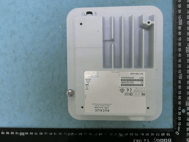
S9GT350C
Mar 23, 2021Access point
Equipment Class
NII - Unlicensed National Information Infrastructure TX
S9GT350D
Mar 10, 2021Access point
Equipment Class
DTS - Digital Transmission System