S9GVX211XWireless 802.11b/g USB Adaptor (2.4GHz)
Ruckus Wireless, Inc.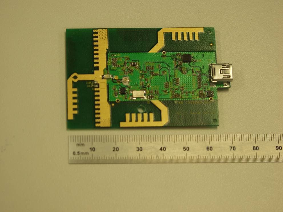
Click to zoom
Application Details
- Equipment Class
- DTS - Digital Transmission System
- Date of Grant
- Aug 31, 2006
- Application Purpose
- Original Equipment
- Date of Application
- Aug 31, 2006
- Equipment Note
- Wireless 802.11b/g USB Adaptor (2.4GHz)
- Frequency Range
- 2412.00000000 - 2462.00000000
- Company
- Ruckus Wireless, Inc.
- Country
- United States
Documents & Files
Document Text
Text extracted from the exhibit documents filed with the FCC. Open a document above to read the original.
Users Manual
VX2110 User Manual Ruckus Wireless, Inc. 880 W. Maude Ave. Sunnyvale, CA 94085 1.0 Introduction The Ruckus Wireless VX2110 is an 802.11b/g wireless module operating in the 2.4 GHz band. It is designed to operate as a slave device to a USB host processor, and is compatible with the USB 1.1 and 2.0 specifications. 2.0 User Information Changes or modifications not expressly approved by the party responsible for compliance could void the user's authority to operate the equipment (per FCC Part 15.21). 3.0 RF Exposure As a mobile and fixed RF device, this device must have at least 20cm separation from the user . 4.0 Operation Plug the mini-B plug into the VX2110. Then plug the other end of the USB cable into the host. The LED on the VX2110 will light indicating that the driver is loaded and the device has power. The remaining steps in setting up the mode of operation will depend on the type of host operating system used and the application software.
Cover Letter(s)
880 West Maude Avenue, Suite 101 TEL + .650.265.4200 Sunnyvale, CA 94085 USA FAX +.480.738.2065 www.ruckuswireless.com August 30, 2006 The Device, FCC ID: S9GVX211X, is seeking FCC authorization as a modular transmitter. The EUT meets the requirement for modular approval as detailed in FCC Public Notice DA 00-1407. Compliance to each of the requirements is described below: 1. The modular transmitter must have its own RF shielding. ¾ S9GVX211X has an RF shield on all radio components. 2. The modular transmitter must have buffered modulation/data. ¾ All data inputs are buffered. No direct access to the radio is available. 3. The modular transmitter must have its own power supply regulation. ¾ S9GVX211X regulates incoming power. Only unregulated DC power is required. 4. The modular transmitter must comply with the antenna requirements of Section 15.203 and 15.204(c). ¾ S9GVX211X uses both permanently attached antennas and an antenna connected using a U.FL connector, which is only accessible inside the enclosure. 5. The modular transmitter must be tested in a stand-alone configuration. ¾ Power will be supplied during testing via a test fixture with the device fully exposed. The control for the device is available via a USB connector on the test fixture. 6. The modular transmitter must be labeled with its own FCC ID number. ¾ S9GVX211X will have a label on the exposed plastic enclosure. 7. The modular transmitter must comply with any specific rule or operating requirements applicable to the transmitter and the manufacturer must provide adequate instructions along with the module to explain any such requirements. ¾ Operation is explained in the VX2110 User Manual. 8. The modular transmitter must comply with any applicable RF exposure requirements. ¾ S9GVX211X complies with all applicable RF exposure requirements, including those in DA 00-1407. Sincerely, Victor Shtrom
External Photos
EXHIBIT C - EUT PHOTOGRAPHS EUT – Main PCB Component Side View EUT – Main PCB Component Side with Shielding View EUT – Main PCB Solder Side View EUT – Main PCB Solder Side View 1 EUT – Antenna PCB Top View EUT – Antenna PCB Bottom View
ID Label/Location Info
EXHIBIT A - FCC ID LABEL INFORMATION Proposed FCC ID Label Proposed Label Location on EUT Main PCB Component Side View /FCC ID Label This device complies with part 15 of the FCC Rules. Operation is subject to the following two conditions: (1) This device may not cause harmful interference, and (2) this device must accept any interference received, including interference that may cause undesired operation. FCC ID: SG9VX211X IC: 5912A-VX211X
Internal Photos
EXHIBIT C - EUT PHOTOGRAPHS EUT – Main PCB Component Side View EUT – Main PCB Component Side with Shielding View EUT – Main PCB Solder Side View EUT – Main PCB Solder Side View 1 EUT – Antenna PCB Top View EUT – Antenna PCB Bottom View
RF Exposure Info
§15.247(e)(i),§2.1091 - RF EXPOSURE According to §15.247(e)(i) and §1.1307(b)(1), systems operating under the provisions of this section shall be operated in a manner that ensures that the public is not exposed to radio frequency energy level in excess of the Commission’s guidelines. According to §1.1310 and §2.1091 RF exposure is calculated. Limits for General Population/Uncontrolled Exposure Frequency Range (MHz) Electric Field Strength (V/m) Magnetic Field Strength (A/m) Power Density (mW/cm 2 ) Averaging Time (minute) Limits for General Population/Uncontrolled Exposure 0.3-1.34 614 1.63 *(100) 30 1.34-30 824/f 2.19/f *(180/f 2 ) 30 30-300 27.5 0.073 0.2 30 300-1500 / / f/1500 30 1500-100,000 / / 1.0 30 f = frequency in MHz * = Plane-wave equivalent power density MPE Prediction Predication of MPE limit at a given distance Equation from page 18 of OET Bulletin 65, Edition 97-01 S = PG/4πR² Where: S = power density P = power input to antenna G = power gain of the antenna in the direction of interest relative to an isotropic radiator R = distance to the center of radiation of the antenna Maximum peak output power at antenna input terminal: 18.3 (dBm ) Maximum peak output power at antenna input terminal: 67.61 (mW) Prediction distance: 20 (cm) Predication frequency: 2437 (MHz) Antenna Gain (typical): 4.98 (dBi) Antenna gain: 3.15 (numeric) Power density at predication frequency at 20 cm: 0.042(mW/cm 2 ) MPE limit for uncontrolled exposure at prediction frequency: 1.0 (mW/cm 2 ) Test Result The EUT is a modular device. The power density level at 20 cm is 0.042mW/cm², which is below the uncontrolled exposure limit of 1.0mW/cm² at 2437 MHz. for VX211X.
Test Setup Photos
EXHIBIT B - TEST SETUP PHOTOGRAPHS Conducted Emissions - Front View Conducted Emissions – Rear View Radiated Emissions - Front View Radiated Emissions - Rear View Radiated Emissions - Front View1 Radiated Emissions - Rear View1
Contact Information
Applicant
Ivaylo Tankov(Principal Wireless Compliance Engineering)
Test Firm
Bay Area Compliance LaboratoryJohn Chan
Technical Specifications
| # | Rule Parts | Frequency Range | Power Output |
|---|---|---|---|
| 2 | 15C | 2.41 GHz - 2.46 GHz | 61.70 mW |
Other Applications from Ruckus Wireless, Inc.
S9GR650P
Jul 11, 2021R650p Access Point
Equipment Class
DTS - Digital Transmission System
S9GR350
Jun 30, 2021Access Point
Equipment Class
NII - Unlicensed National Information Infrastructure TX
S9GR550P
Jun 30, 2021Wireless Access Point
Equipment Class
DTS - Digital Transmission System
S9GT350C
Mar 23, 2021Access point
Equipment Class
NII - Unlicensed National Information Infrastructure TX
S9GT350D
Mar 10, 2021Access point
Equipment Class
DTS - Digital Transmission System