S9GZF7761CMDual-Band 802.11 a/b/g/n Industrial Access Point
Ruckus Wireless, Inc.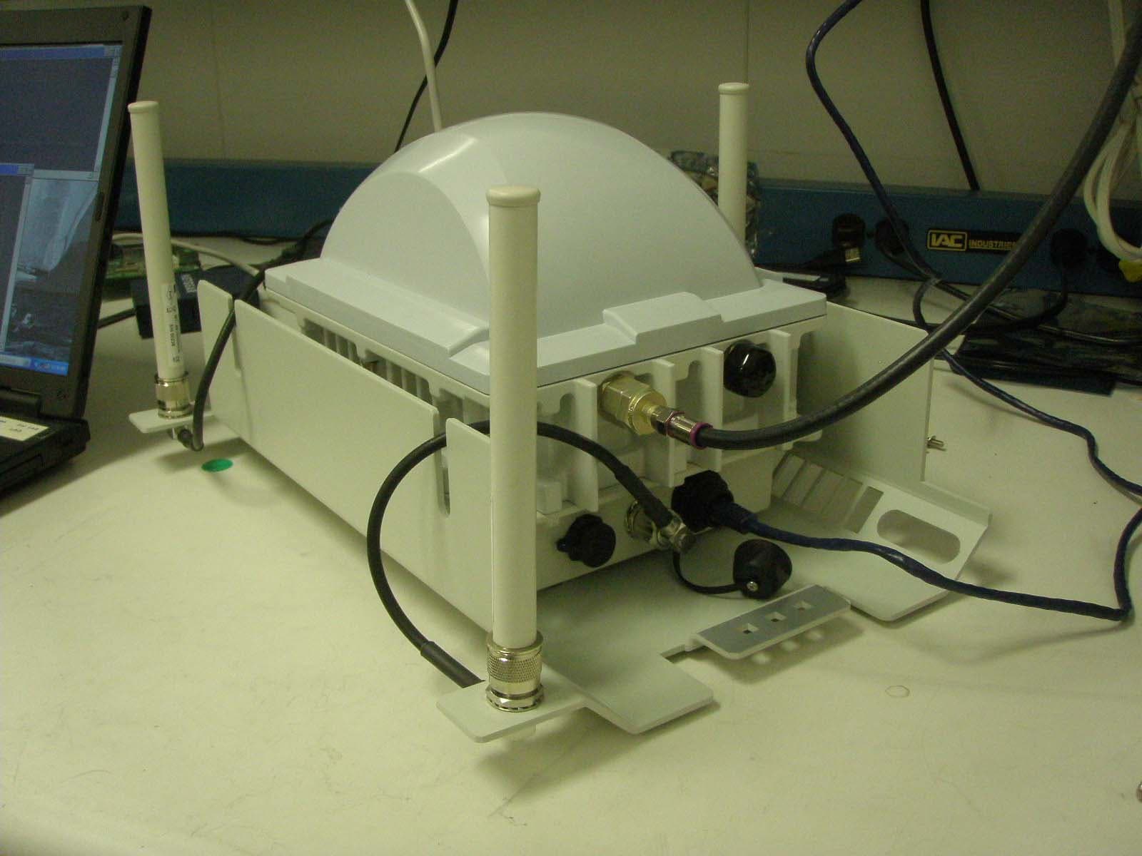
Click to zoom
Application Details
- Equipment Class
- NII - Unlicensed National Information Infrastructure TX
- Date of Grant
- Mar 10, 2011
- Application Purpose
- Original Equipment
- Date of Application
- Mar 10, 2011
- Equipment Note
- Dual-Band 802.11 a/b/g/n Industrial Access Point
- Frequency Range
- 5190.00000000 - 5230.00000000
- Company
- Ruckus Wireless, Inc.
- Country
- United States
Documents & Files
Document Text
Text extracted from the exhibit documents filed with the FCC. Open a document above to read the original.
Users Manual
Ruckus Wireless ™ ZoneFlex ™ 7761CM Dual Band 802.11n Outdoor Access Point with Integrated Cable Modem Installation Guide Part Number 800-70290-001 Published March 2010 www.ruckuswireless.com i 1About This Installation Guide . . . . . . . . . . . . . . . . . . . . . . . . . . . . . . . . . . . . . . . . . . . . . . . . 1 Related Documentation . . . . . . . . . . . . . . . . . . . . . . . . . . . . . . . . . . . . . . . . . . . . . . . . . . . 1 Using ZoneDirector to Manage the CMAP . . . . . . . . . . . . . . . . . . . . . . . . . . . . . . . . . . . . 1 Terms Used in This Guide . . . . . . . . . . . . . . . . . . . . . . . . . . . . . . . . . . . . . . . . . . . . . . . . . 1 2Unpacking the CMAP . . . . . . . . . . . . . . . . . . . . . . . . . . . . . . . . . . . . . . . . . . . . . . . . . . . . . . . 2 Package Contents . . . . . . . . . . . . . . . . . . . . . . . . . . . . . . . . . . . . . . . . . . . . . . . . . . . . . . . . 2 3Preparing for Installation . . . . . . . . . . . . . . . . . . . . . . . . . . . . . . . . . . . . . . . . . . . . . . . . . . . . 4 Preconfiguring the Access Point (Standalone Only) . . . . . . . . . . . . . . . . . . . . . . . . . . . . 4 Step 1: Prepare the Administrative Computer . . . . . . . . . . . . . . . . . . . . . . . . . . . . . . . . 5 Step 2: Supply Power to the CMAP . . . . . . . . . . . . . . . . . . . . . . . . . . . . . . . . . . . . . . . . 8 Step 3: Log Into the Access Point’s Web Interface . . . . . . . . . . . . . . . . . . . . . . . . . . . . 9 Step 4: Configure the Wireless Settings . . . . . . . . . . . . . . . . . . . . . . . . . . . . . . . . . . . . 10 Step 5: Disconnect the CMAP from the Administrative Computer . . . . . . . . . . . . . . 14 Step 6: Restore the Administrative Computer’s Network Settings . . . . . . . . . . . . . . 14 Pointing the CMAP to ZoneDirector . . . . . . . . . . . . . . . . . . . . . . . . . . . . . . . . . . . . . . . . 14 Use SSH to Set the ZoneDirector IP Address on the CMAP . . . . . . . . . . . . . . . . . . . . 15 Configure Option 43 on the DHCP Server (ZoneDirector Management Only) . . . . . 16 4Hardware Features . . . . . . . . . . . . . . . . . . . . . . . . . . . . . . . . . . . . . . . . . . . . . . . . . . . . . . . . 28 Weight and Dimensions . . . . . . . . . . . . . . . . . . . . . . . . . . . . . . . . . . . . . . . . . . . . . . . . . . 30 Connectors . . . . . . . . . . . . . . . . . . . . . . . . . . . . . . . . . . . . . . . . . . . . . . . . . . . . . . . . . . . . 31 Ethernet/PoE-Out Port . . . . . . . . . . . . . . . . . . . . . . . . . . . . . . . . . . . . . . . . . . . . . . . . . . . 31 LEDs . . . . . . . . . . . . . . . . . . . . . . . . . . . . . . . . . . . . . . . . . . . . . . . . . . . . . . . . . . . . . . . . . . 31 Supported Power Sources . . . . . . . . . . . . . . . . . . . . . . . . . . . . . . . . . . . . . . . . . . . . . . . . 33 Heaters . . . . . . . . . . . . . . . . . . . . . . . . . . . . . . . . . . . . . . . . . . . . . . . . . . . . . . . . . . . . . . . . 33 5Before You Begin . . . . . . . . . . . . . . . . . . . . . . . . . . . . . . . . . . . . . . . . . . . . . . . . . . . . . . . . . 33 Prepare the Required Hardware and Tools . . . . . . . . . . . . . . . . . . . . . . . . . . . . . . . . . . 33 Perform a Site Survey . . . . . . . . . . . . . . . . . . . . . . . . . . . . . . . . . . . . . . . . . . . . . . . . . . . . 34 Contents ii 6Powering the CMAP . . . . . . . . . . . . . . . . . . . . . . . . . . . . . . . . . . . . . . . . . . . . . . . . . . . . . . . 35 Using DC Power (Staging or Debugging Only) . . . . . . . . . . . . . . . . . . . . . . . . . . . . . . . 35 Using Power Over Cable (Actual Deployment) . . . . . . . . . . . . . . . . . . . . . . . . . . . . . . . 35 7Verifying Access Point Operation . . . . . . . . . . . . . . . . . . . . . . . . . . . . . . . . . . . . . . . . . . . . 36 8Switching LEDs to Cable Modem Mode. . . . . . . . . . . . . . . . . . . . . . . . . . . . . . . . . . . . . . . 36 Using the AP’s Web Interface to Switch to CM Mode . . . . . . . . . . . . . . . . . . . . . . . . . . 37 Using SNMP to Switch to CM Mode . . . . . . . . . . . . . . . . . . . . . . . . . . . . . . . . . . . . . . . . 38 9Resetting the Access Point to Factory Default Settings . . . . . . . . . . . . . . . . . . . . . . . . . . 40 Using the Reset Switch on the DC Power Supply . . . . . . . . . . . . . . . . . . . . . . . . . . . . . 40 Using SNMP to Reset the Access Point . . . . . . . . . . . . . . . . . . . . . . . . . . . . . . . . . . . . . 41 Before You Begin . . . . . . . . . . . . . . . . . . . . . . . . . . . . . . . . . . . . . . . . . . . . . . . . . . . . . . 41 10Resetting the CM to Factory Default Settings . . . . . . . . . . . . . . . . . . . . . . . . . . . . . . . . . . 43 Before You Begin . . . . . . . . . . . . . . . . . . . . . . . . . . . . . . . . . . . . . . . . . . . . . . . . . . . . . . 43 11Mounting the CMAP. . . . . . . . . . . . . . . . . . . . . . . . . . . . . . . . . . . . . . . . . . . . . . . . . . . . . . . 44 12Installing the Antennas . . . . . . . . . . . . . . . . . . . . . . . . . . . . . . . . . . . . . . . . . . . . . . . . . . . . . 45 13What to Do Next . . . . . . . . . . . . . . . . . . . . . . . . . . . . . . . . . . . . . . . . . . . . . . . . . . . . . . . . . . 46 Change the Administrative Password . . . . . . . . . . . . . . . . . . . . . . . . . . . . . . . . . . . . . . . 46 Read Related Documentation . . . . . . . . . . . . . . . . . . . . . . . . . . . . . . . . . . . . . . . . . . . . . 46 14Troubleshooting . . . . . . . . . . . . . . . . . . . . . . . . . . . . . . . . . . . . . . . . . . . . . . . . . . . . . . . . . . 46 Retrieving the CM’s MAC Address . . . . . . . . . . . . . . . . . . . . . . . . . . . . . . . . . . . . . . . . . 46 How Radio Frequency Scanning Works . . . . . . . . . . . . . . . . . . . . . . . . . . . . . . . . . . . . . 47 Contacting Ruckus Wireless Support . . . . . . …
Text truncated - open the document above for the full version.
Users Manual
Professional installation instruction 1. Installation personal: This product is designed for specific application and needs to be installed by a qualified personal who has RF and related rule knowledge. The general user shall not attempt to install or change the setting. 2. Installation location: The product shall be installed at a location where the radiating antenna can be kept 20 cm from nearby person in normal operation condition to meet regulatory RF exposure requirement. 3. External antenna: Use only the antennas which have been approved by Ruckus Wireless. The non-approved antenna(s) may produce unwanted spurious or excessive RF transmitting power which may lead to the violation of FCC limit and is prohibited. 4. Installation procedure: Please refer to Installation Manual for the detail. 5. Warning: Please carefully select the installation position and make sure that the final output power does not exceed the limit set force in US Rule CFR 47 part 15 section 15.247 & 15.407 or Canada IC RSS-210. The violation of the rule could lead to serious federal penalty. Federal Communications Commission Notices This device complies with Part 15 of the FCC rules. Operation is subject to the following two conditions: (1) this device may not cause harmful interference, and (2) this device must accept any interference received, including interference that may cause undesired operation. Changes or alterations to the Ruckus Wireless System not expressly approved by Ruckus could void the user’s authority to operate the equipment. This equipment has been tested and found to comply with the limits for a Class A digital device, pursuant to part 15 of the FCC Rules. These limits are designed to provide reasonable protection against harmful interference when the equipment is operated in a commercial environment. This equipment generates, uses, and can radiate radio frequency energy and, if not installed and used in accordance with the instruction manual, may cause harmful interference to radio communications. Operation of this equipment in a residential area is likely to cause harmful interference in which case the user will be required to correct the interference at his own expense. To satisfy RF exposure requirements, this device and its antenna must operate with a separation distance of at least 20 centimeters from all persons and must not be co- located or operating in conjunction with any other antenna or transmitter. External Antenna This device has been designed to operate with a patch antenna, and having a maximum gain of 6 dBi. Other antennatypes or having a gain greater than 6 dBi are strictly prohibited for use with this device. The required antenna impedance is 50 ohms. Industry Canada Statement This device complies with Industry Canada ICES-003 and RSS210 rules. Operation is subject to the following two conditions: 1. This device may not cause interference and 2. This device must accept any interference, including interference that may cause undesired operation of the device. Cet appareil est conforme aux normes NMB003 et RSS210 d'Industrie Canada. Le fonctionnement est soumis aux conditions suivantes : 1. Ce périphérique ne doit pas causer d'interférences; 2. Ce périphérique doit accepter toutes les interférences reçues, y compris celles qui risquent d'entraîner un fonctionnement indésirable. This device has been designed to operate with an antenna having a maximum gain of 6 dBm. Antenna having a higher gain is strictly prohibited per regulations of Industry Canada. The required antenna impedance is 50 ohms. Australia Statement This device complies with the ACMA requirements for a Wi-Fi device namely Radio Communications (Low Impact Potential Devices) Class Licence 2000 Amd. 1:2007 and Radiocommunications (Compliance Labelling – Electromagnetic Radiation) Notice 2003. The equipment complies with the ACMA requirements for radiation exposure for a "general user/non-aware user". This equipment should be installed and operated with a minimum distance of 20 cm between the radiator and your body. This equipment complies with the Australian safety requirements. European Union Notices This product only supplied by Limited Power sources (sub-clause 2.5 of standard EN 60950-1) Compliance Information for 2.4GHz, 5GHz Wireless Products The following standards were applied during the assessment of the product against the requirements of the Directive 1999/5/EC: Radio: EN 300 328, EN 301 893 EMC: EN 301 489-1, EN 301 489-17 Safety: EN 60950, EN 50385 The frequency band 5150 – 5350 MHz is restricted to indoor use. National Restrictions This product may be used in all EU countries (and other countries following the EU directive 1999/5/EC) without any limitation except for the countries mentioned below: Ce produit peut être utilisé dans tous les pays de l’UE (et dans tous les pays ayant transposés la directive 1999/5/CE) sans aucune limitation, excepté pour les pays mentionnés ci-dessous: Questo prodotto è utilizzabile in tutte i paesi EU (ed in tutti gli altri paesi che seguono le direttive EU 1999/5/EC) senza nessuna limitazione, eccetto per i paesii menzionati di seguito: Das Produkt kann in allen EU Staaten ohne Einschränkungen eingesetzt werden (sowie in anderen Staaten die der EU Direktive 1999/5/CE folgen) mit Außnahme der folgenden aufgeführten Staaten: France In case the product is used outdoors, the output power is restricted in some parts of the band. See the table below or check http://www.arcep.fr/ for more details. Dans la cas d’une utilisation en extérieur, la puissance de sortie est limitée pour certaines parties de la bande. Reportezvous à la table 1 ou visitez http://www.arcep.fr/ pour de plus amples détails. Location Frequency Range (MHz) Power (EIRP) Indoor (No restrictions) 2400-2483.5 100 mW (20 dBm) Outdoor 2400-2454 [2454-2483.5] 100 mW (20 dBm) [10 mW(10 dBm)] Italy This product meets the National Radio Interface and the requirements specified in the National Frequency Alloca…
Text truncated - open the document above for the full version.
Attestation Statements
880 West Maude Avenue, Suite 101 TEL + .650.265.4200 Sunnyvale, CA 94085 USA FAX +.480.738.2065 www.ruckuswireless.com Compliance Certification Services Certification Division 47173 Benicia Street Fremont, CA 94538 February 25, 2011 To whom it may concern: We, the undersigned, hereby authorize the COMPLIANCE CERTIFICATION SERVICES and hereafter referred to as CCS, to act on our behalf in all manners relating to application for equipment authorization, including signing of all documents relating to these matters. Any and all acts carried out by CCS on our behalf shall have the same effect as acts of our own. We, the undersigned, hereby certify that we are not subject to a denial of federal benefits, that includes FCC benefits, pursuant to Section 5301 of the Anti-Drug Abuse Act of 1988, 21 U.S.C. 853(a). In authorizing CCS as our agent, we still recognize that we are responsible to: a) comply with the relevant provisions of the certification program; b) make all necessary arrangements for the conduct of the evaluation, including provision for examining documentation and access to all areas, records (including internal audit reports) and personnel for the purposes of evaluation (e.g. testing, inspection, assessment, surveillance, reassessment) and resolution of complaints; c) make claims regarding certification only in respect of the scope for which certification has been granted; d) do not use our product certification in such a manner as to bring the Certification Division into disrepute and not make any statement regarding our product certification which the Certification Division may consider misleading or unauthorized; e) upon suspension or cancellation of certification, discontinue use of all advertising matter that contains any reference thereto and return any certification documents as required by the Certification Division; f) use certification only to indicate the products are certified as being in conformity with specified standards; 880 West Maude Avenue, Suite 101 TEL + .650.265.4200 Sunnyvale, CA 94085 USA FAX +.480.738.2065 www.ruckuswireless.com g) endeavor to ensure that no certificate or report nor any part thereof is used in a misleading manner; h) ensure that any reference to our product certification in communication media such as documents, brochures or advertising, complies with the requirements of the Certification Division; i) keep a record of all complaints made known to the us relating to the product’s compliance with requirements of the relevant standard and to make these records available to the Certification Division when requested; j) take appropriate action with respect to such complaints and any deficiencies found in products or services that affect compliance with the requirements for certification; k) document the actions taken. This authorization is valid until further written notice from the applicant. Sincerely, Craig Owens Director, Hardware Engineering [email protected]
Attestation Statements
880 West Maude Avenue, Suite 101 TEL + .650.265.4200 Sunnyvale, CA 94085 USA FAX +.480.738.2065 www.ruckuswireless.com FEDERAL COMMUNICATIONS COMMISSIONS Authorization and Evaluation Division 7435 Oakland Mills Road Columbia, MD 21046 February 25, 2011 Re: Request for Confidentiality Dear Examiner: In reference to the application under FCC ID: S9GZF7761CM, and pursuant to Sections 0.457(d)(1)(ii) and 0.459 of the Commission's Rules, the Applicant hereby requests confidential treatment of the accompanying information as outlined below: Schematic Diagram Block Diagram Theory of Operation Antenna Specification The above materials contain trade secrets and proprietary information not customarily released to the public. The public disclosure of these matters might be harmful to the Applicant and provide unjustified benefits to its competitors. In additional to above mentioned documents, pursuant to Public Notice DA 04-1705 of the Commission’s policy, in order to comply with the marketing regulations in 47 CFR §2.803 and the importation rules in 47 CFR §2.1204, while ensuring that business sensitive information remains confidential until the actual marketing of newly authorized devices. We are requesting the commission to grant short-term confidentiality request on the following attachments until May 26, 2011: Internal and External Photographs Test Configuration Photographs It is our understanding that all measurement test reports, FCC ID label format and correspondent during certification review process cannot be granted as confidential documents and those information will be available for public review once the grant of equipment authorization is issued. The Applicant understands that pursuant to Rule 0.457(d)(1)(ii), disclosure of this Application and all accompanying documentation will not be made before the date of the Grant for this application. Sincerely, Craig Owens Director, Hardware Engineering
ID Label/Location Info
Label Location Outline FCC ID: S9GZF7761CM IC: 5912A-ZF7761CM Model: ZoneFlex7761-CM LABEL
ID Label/Location Info
860-76298-001-B Made in Taiwan FCC ID:S9GZF7761CM IC:5912A-ZF7761CM ZoneFlex 7761-CM Access Point 45-90VAC/2A input BLACK PMS 021C 1. Dielines/cutlines do not print 2. Replace “Taiwan” with country of manufacture 3. P/N 877-76298-001 rev. B 4. Colors: I.T.E. E315548 This device complies with part 15 of the FCC Rules. Operation is subject to the following two conditions: (1) This device may not cause harmful interference, and (2) this device must accept any interference received, including interference that may cause undesired operation.
RF Exposure Info
REPORT NO: 10U13475-3 DATE: MARCH 3, 2011 FCC ID: S9GZF7761CM IC: 5912A-ZF7761CM Page 153 of 161 COMPLIANCE CERTIFICATION SERVICES FORM NO: CCSUP4701C 47173 BENICIA STREET, FREMONT, CA 94538, USA TEL: (510) 771-1000 FAX: (510) 661-0888 This report shall not be reproduced except in full, without the written approval of CCS. 10. MAXIMUM PERMISSIBLE EXPOSURE FCC RULES §1.1310 The criteria listed in Table 1 shall be used to evaluate the environmental impact of human exposure to radio-frequency (RF) radiation as specified in §1.1307(b), except in the case of portable devices which shall be evaluated according to the provisions of §2.1093 of this chapter. REPORT NO: 10U13475-3 DATE: MARCH 3, 2011 FCC ID: S9GZF7761CM IC: 5912A-ZF7761CM Page 154 of 161 COMPLIANCE CERTIFICATION SERVICES FORM NO: CCSUP4701C 47173 BENICIA STREET, FREMONT, CA 94538, USA TEL: (510) 771-1000 FAX: (510) 661-0888 This report shall not be reproduced except in full, without the written approval of CCS. IC RULES IC Safety Code 6, Section 2.2.1 (a) A person other than an RF and microwave exposed worker shall not be exposed to electromagnetic radiation in a frequency band listed in Column 1 of Table 5, if the field strength exceeds the value given in Column 2 or 3 of Table 5, when averaged spatially and over time, or if the power density exceeds the value given in Column 4 of Table 5, when averaged spatially and over time. REPORT NO: 10U13475-3 DATE: MARCH 3, 2011 FCC ID: S9GZF7761CM IC: 5912A-ZF7761CM Page 155 of 161 COMPLIANCE CERTIFICATION SERVICES FORM NO: CCSUP4701C 47173 BENICIA STREET, FREMONT, CA 94538, USA TEL: (510) 771-1000 FAX: (510) 661-0888 This report shall not be reproduced except in full, without the written approval of CCS. EQUATIONS Power density is given by: S = EIRP / (4 * Pi * D^2) where S = Power density in W/m^2 EIRP = Equivalent Isotropic Radiated Power in W D = Separation distance in m Power density in units of W/m^2 is converted to units of mWc/m^2 by dividing by 10. Distance is given by: D = SQRT (EIRP / (4 * Pi * S)) where D = Separation distance in m EIRP = Equivalent Isotropic Radiated Power in W S = Power density in W/m^2 For multiple colocated transmitters operating simultaneously in frequency bands where the limit is identical, the total power density is calculated using the total EIRP obtained by summing the Power * Gain product (in linear units) of each transmitter. Total EIRP = (P1 * G1) + (P2 * G2) + ... + (Pn * Pn) where Px = Power of transmitter x Gx = Numeric gain of antenna x In the table(s) below, Power and Gain are entered in units of dBm and dBi respectively and conversions to linear forms are used for the calculations. LIMITS From FCC §1.1310 Table 1 (B), the maximum value of S = 1.0 mW/cm^2 From IC Safety Code 6, Section 2.2 Table 5 Column 4, S = 10 W/m^2 REPORT NO: 10U13475-3 DATE: MARCH 3, 2011 FCC ID: S9GZF7761CM IC: 5912A-ZF7761CM Page 156 of 161 COMPLIANCE CERTIFICATION SERVICES FORM NO: CCSUP4701C 47173 BENICIA STREET, FREMONT, CA 94538, USA TEL: (510) 771-1000 FAX: (510) 661-0888 This report shall not be reproduced except in full, without the written approval of CCS. RESULTS Notes: Antenna Gain for 11a is the combined antenna gain for multiple chains. Antenna gain for HT20 and HT40 is the maximum antenna gain of multiple chains. Output power is the combined output power for multiple chains. ModeBandMPEOutputAntennaFCC PowerIC Power DistancePowerGainDensityDensity (cm)(dBm)(dBi)(mW/cm^2)(W/m^2) W LAN , 11a, 20M5.2 GHz20.012.2910.270.040.36 WLAN, 11n HT205.2 GHz20.015.715.500.030.26 WLAN, 11n HT405.2 GHz20.016.855.500.030.34
Test Report
FCC CFR47 PART 15 SUBPART E INDUSTRY CANADA RSS-210 ISSUE 8 CERTIFICATION TEST REPORT FOR Dual-Band 802.11 a/b/g/n Industrial Access Point with Integrated DOCSIS 3.0 Modem MODEL NUMBER: ZoneFlex7761-CM FCC ID: S9GZF7761CM IC: 5912A-ZF7761CM REPORT NUMBER: 10U13475-3 ISSUE DATE: MARCH 3, 2011 Prepared for RUCKUS WIRELESS 880 WEST MAUDE AVE., SUITE 101 SUNNYVALE, CA 94085, U.S.A. Prepared by COMPLIANCE CERTIFICATION SERVICES 47173 BENICIA STREET FREMONT, CA 94538, U.S.A. TEL: (510) 771-1000 FAX: (510) 661-0888 REPORT NO: 10U13475-3 DATE: MARCH 3, 2011 FCC ID: S9GZF7761CM IC: 5912A-ZF7761CM Page 2 of 161 COMPLIANCE CERTIFICATION SERVICES FORM NO: CCSUP4701C 47173 BENICIA STREET, FREMONT, CA 94538, USA TEL: (510) 771-1000 FAX: (510) 661-0888 This report shall not be reproduced except in full, without the written approval of CCS. Revision History Rev. Issue Date Revisions Revised By -- 03/03/11 Initial Issue F. Ibrahim REPORT NO: 10U13475-3 DATE: MARCH 3, 2011 FCC ID: S9GZF7761CM IC: 5912A-ZF7761CM Page 3 of 161 COMPLIANCE CERTIFICATION SERVICES FORM NO: CCSUP4701C 47173 BENICIA STREET, FREMONT, CA 94538, USA TEL: (510) 771-1000 FAX: (510) 661-0888 This report shall not be reproduced except in full, without the written approval of CCS. TABLE OF CONTENTS 1. ATTESTATION OF TEST RESULTS ................................ 5 2. TEST METHODOLOGY ................................ 6 3. FACILITIES AND ACCREDITATION ................................ 6 4. CALIBRATION AND UNCERTAINTY ................................ 6 4.1. MEASURING INSTRUMENT CALIBRATION ............................................................... 6 4.2. SAMPLE CALCULATION.............................................................................................. 6 4.3. MEASUREMENT UNCERTAINTY................................................................................ 6 5. EQUIPMENT UNDER TEST ................................ 7 5.1. DESCRIPTION OF EUT................................................................................................ 7 5.2. MAXIMUM OUTPUT POWER....................................................................................... 7 5.3. DESCRIPTION OF AVAILABLE ANTENNAS............................................................... 8 5.4. SOFTWARE AND FIRMWARE..................................................................................... 8 5.5. WORST-CASE CONFIGURATION AND MODE .......................................................... 8 5.6. DESCRIPTION OF TEST SETUP................................................................................. 9 6. TEST AND MEASUREMENT EQUIPMENT .............................. 11 7. ANTENNA PORT TEST RESULTS .............................. 12 7.1. 802.11a THREE CHAIN LEGACY MODE IN THE 5.2 GHz BAND............................. 12 7.1.1. 26 dB and 99% BANDWIDTH ............................................................................. 12 7.1.2. OUTPUT POWER ............................................................................................... 22 7.1.3. AVERAGE POWER ............................................................................................ 33 7.1.4. PEAK POWER SPECTRAL DENSITY................................................................ 34 7.1.5. PEAK EXCURSION ............................................................................................ 39 7.1.6. CONDUCTED SPURIOUS EMISSIONS............................................................. 50 7.2. 802.11n THREE CHAINS HT20 MODE IN THE 5.2 GHz BAND ................................ 54 7.2.1. 26 dB and 99% BANDWIDTH ............................................................................. 54 7.2.2. OUTPUT POWER ............................................................................................... 64 7.2.3. AVERAGE POWER ............................................................................................ 75 7.2.4. PEAK POWER SPECTRAL DENSITY................................................................ 76 7.2.5. PEAK EXCURSION ............................................................................................ 80 7.2.6. CONDUCTED SPURIOUS EMISSIONS............................................................. 91 7.3. 802.11n THREE CHAINS HT40 MODE IN THE 5.2 GHz BAND ................................ 95 7.3.1. 26 dB and 99% BANDWIDTH ............................................................................. 95 7.3.2. OUTPUT POWER ............................................................................................. 102 7.3.3. AVERAGE POWER .......................................................................................... 110 7.3.4. PEAK POWER SPECTRAL DENSITY.............................................................. 111 7.3.5. PEAK EXCURSION .......................................................................................... 114 7.3.6. CONDUCTED SPURIOUS EMISSIONS........................................................... 122 7.4. RECEIVER CONDUCTED SPURIOUS EMISSIONS ............................................... 125 REPORT NO: 10U13475-3 DATE: MARCH 3, 2011 FCC ID: S9GZF7761CM IC: 5912A-ZF7761CM Page 4 of 161 COMPLIANCE CERTIFICATION SERVICES FORM NO: CCSUP4701C 47173 BENICIA STREET, FREMONT, CA 94538, USA TEL: (510) 771-1000 FAX: (510) 661-0888 This report shall not be reproduced except in full, without the written approval of CCS. 8. RADIATED TEST RESULTS ............................ 129 8.1. LIMITS AND PROCEDURE ...................................................................................... 129 8.2. TRANSMITTER ABOVE 1 GHz ................................................................................ 130 8.2.1. TX ABOVE 1 GHz FOR 802.11a MODE IN THE 5.2 GHz BAND ..................... 130 8.2.2. TX ABOVE 1 GHz FOR 802.11n HT20 MODE IN THE 5.2 GHz BAND ........... 135 8.2.3. TX ABOVE 1 GHz FOR 802.11n HT40 MODE IN THE 5.2 GHz BAND ........... 140 8.3. WORST-CASE BELOW 1 GHz................................…
Text truncated - open the document above for the full version.
Test Setup Photos
REPORT NO: 10U13475-3 DATE: MARCH 3, 2011 FCC ID: S9GZF7761CM IC: 5912A-ZF7761CM Page 157 of 161 COMPLIANCE CERTIFICATION SERVICES FORM NO: CCSUP4701C 47173 BENICIA STREET, FREMONT, CA 94538, USA TEL: (510) 771-1000 FAX: (510) 661-0888 This report shall not be reproduced except in full, without the written approval of CCS. 11. SETUP PHOTOS ANTENNA PORT CONDUCTED RF MEASUREMENT SETUP ANTENNA PORT CONDUCTED PHOTO REPORT NO: 10U13475-3 DATE: MARCH 3, 2011 FCC ID: S9GZF7761CM IC: 5912A-ZF7761CM Page 158 of 161 COMPLIANCE CERTIFICATION SERVICES FORM NO: CCSUP4701C 47173 BENICIA STREET, FREMONT, CA 94538, USA TEL: (510) 771-1000 FAX: (510) 661-0888 This report shall not be reproduced except in full, without the written approval of CCS. RADIATED RF MEASUREMENT SETUP RADIATED FRONT PHOTO REPORT NO: 10U13475-3 DATE: MARCH 3, 2011 FCC ID: S9GZF7761CM IC: 5912A-ZF7761CM Page 159 of 161 COMPLIANCE CERTIFICATION SERVICES FORM NO: CCSUP4701C 47173 BENICIA STREET, FREMONT, CA 94538, USA TEL: (510) 771-1000 FAX: (510) 661-0888 This report shall not be reproduced except in full, without the written approval of CCS. RADIATED BACK PHOTO REPORT NO: 10U13475-3 DATE: MARCH 3, 2011 FCC ID: S9GZF7761CM IC: 5912A-ZF7761CM Page 160 of 161 COMPLIANCE CERTIFICATION SERVICES FORM NO: CCSUP4701C 47173 BENICIA STREET, FREMONT, CA 94538, USA TEL: (510) 771-1000 FAX: (510) 661-0888 This report shall not be reproduced except in full, without the written approval of CCS. POWERLINE CONDUCTED EMISSIONS MEASUREMENT SETUP LINE CONDUCTED FRONT PHOTO REPORT NO: 10U13475-3 DATE: MARCH 3, 2011 FCC ID: S9GZF7761CM IC: 5912A-ZF7761CM Page 161 of 161 COMPLIANCE CERTIFICATION SERVICES FORM NO: CCSUP4701C 47173 BENICIA STREET, FREMONT, CA 94538, USA TEL: (510) 771-1000 FAX: (510) 661-0888 This report shall not be reproduced except in full, without the written approval of CCS. END OF REPORT LINE CONDUCTED BACK PHOTO
Contact Information
Applicant
Ivaylo Tankov(Principal Wireless Compliance Engineering)
Test Firm
Compliance Certification ServicesThu Chan
Technical Specifications
| # | Rule Parts | Frequency Range | Power Output |
|---|---|---|---|
| 3 | 15E | 5.19 GHz - 5.23 GHz | 48.40 mW |
Other Applications from Ruckus Wireless, Inc.
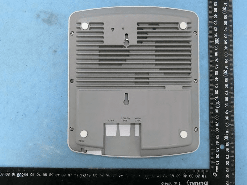
S9GR650P
Jul 11, 2021R650p Access Point
Equipment Class
DTS - Digital Transmission System
S9GR350
Jun 30, 2021Access Point
Equipment Class
NII - Unlicensed National Information Infrastructure TX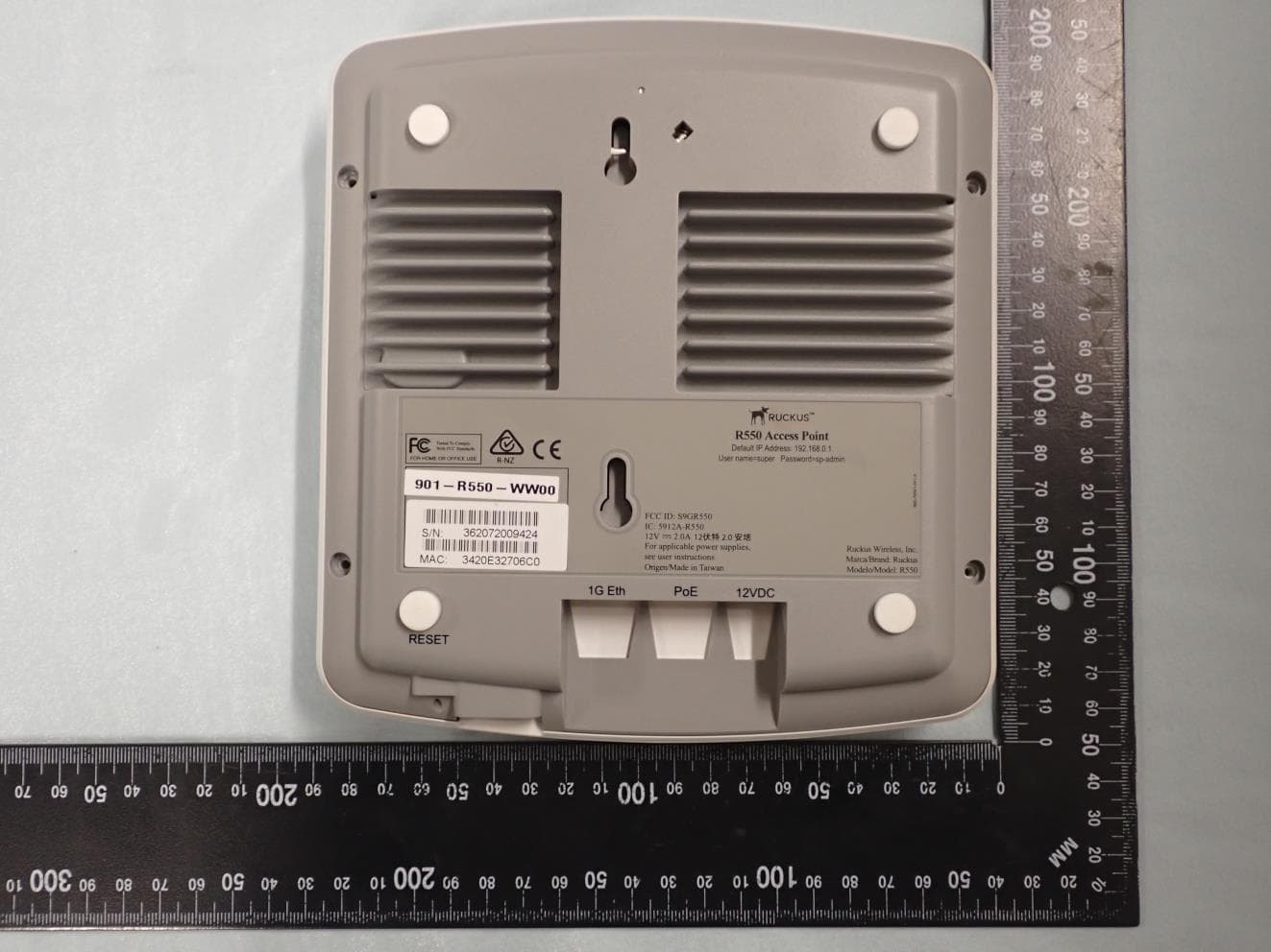
S9GR550P
Jun 30, 2021Wireless Access Point
Equipment Class
DTS - Digital Transmission System
S9GT350C
Mar 23, 2021Access point
Equipment Class
NII - Unlicensed National Information Infrastructure TX
S9GT350D
Mar 10, 2021Access point
Equipment Class
DTS - Digital Transmission System