S9NSPBTLERFSPBTLE-RF Bluetooth Low Energy Module
ST Microelectronics S.R.L.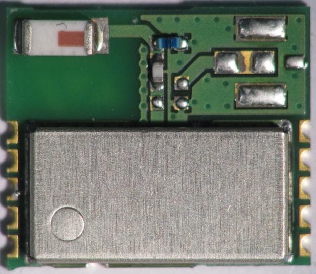
Click to zoom
Application Details
- Equipment Class
- DTS - Digital Transmission System
- Date of Grant
- May 24, 2015
- Application Purpose
- Original Equipment
- Date of Application
- May 21, 2015
- Equipment Note
- SPBTLE-RF Bluetooth Low Energy Module
- Frequency Range
- 2402.00000000 - 2480.00000000
- Company
- ST Microelectronics S.R.L.
- Country
- Italy
Documents & Files
Document Text
Text extracted from the exhibit documents filed with the FCC. Open a document above to read the original.
Users Manual
SPBTLE-RF Bluetooth® V4.1 Smart module Product preview Jan 2015 - rev 0.1 This is preliminary information on a new product now in development or undergoing evaluation. Details are subject to change without notice. www.st.com www.st.com Features Bluetooth Radio - Bluetooth specification v4.1 compliant - Master and slave Smart Bluetooth network processor module - Embedded Bluetooth low energy protocol stack: GAP, GATT, SM, L2CAP, LL, RF-PHY - Bluetooth low energy profiles provided separately - Operating temperature range: -40°C to 85°C Host Interface - SPI, IRQ, and RESET Antenna on board CE, FCC, IC qualified BQE certified Preliminary module picture 11.5 mm x 13.5 mm x 2.0 mm SPBTLE-RF P a g e | 2 Rev 0.1 1 Description The SPBTLE-RF is an easy to use Bluetooth® module, compliant with Bluetooth® v4.1. The module provides a complete RF platform in a tiny form factor. The SPBTLE-RF enables wireless connectivity into electronic devices, not requiring any RF experience or expertise for integration into the final product. The SPBTLE-RF module, being a certified solution, optimizes the time to market of the final applications. The module has been designed for maximum performance in a minimal space. Optimized design allows the integration of a complete working Bluetooth® modem in the minimum possible size. Module interface is SPI serial interface. 2 Applications Watches Fitness, wellness and sports Consumer medical Security/proximity Remote control Home and industrial automation Assisted living Mobile phone peripherals PC peripherals SPBTLE-RF Rev 0.1 P a g e | 3 3 Block Diagram Figure 1. HW block diagram RF antenna Battery or External Supply SPI LINE BLUETOOTH BLUENRG Host Controller interface External LPO (32.768 kHz) 32.768 kHz BLUETOOTH L.E.. 2014 Module Crystal 32 MHz clock SUPPLY FILTER Bead Ferrite RF BALUN + Filter Internal / Ext. 32.768 kHz clock INTERNAL 2.45 GHz OPTIONAL PIN FUNCTION SPBTLE-RF P a g e | 4 Rev 0.1 4 Software Architecture Bluetooth Firmware implementation Figure 2. SPBTLE-RF Application Block Diagaram SPBTLE-RF Rev 0.1 P a g e | 5 5 Hardware Specifications General Conditions (V IN = 2.2V and 25°C) 5.1 Absolute Maximum Ratings Table 1. Absolute maximum rating Rating Min Typical Max Unit Storage temperature range -40 - +85 °C Supply voltage, V IN -0.3 - + 3.9 Volts I/O pin Voltage (V IO five-volt tolerant pin) -0.3 - + 3.9 Volts RF saturation input power - 8 - dBm 5.2 Recommended Operating Conditions Table 2. Recommended operating conditions Rating Min Typical Max Unit Operating Temperature Range -40 - 85 °C Supply Voltage V IN 2.0 3.3 3.6 Volts Signals & I/O Pin Voltage (according Supply Voltage) 2.0 - 3.6 Volts RF Frequency 2402 - 2480 MHz 5.3 Pin assignement Figure 3. Pin connection SPBTLE-RF P a g e | 6 Rev 0.1 Table 3. Pin Assignement Name Type Pin # Description ALT Function V max. Tolerant Initial State SPI Interface SPI_IRQ O 4 SPI IRQ(SLAVE has data for MASTER) V in SPI_CLK I 7 SPI CLOCK (Max. 8 MHz) V in SPI_MISO O 8 SPI MISO (MASTER in / SLAVE out) V in SPI_MOSI I 9 SPI MOSI (MASTER out SLAVE in) V in SPI_CS I 10 SPI “Chip Select” (SPI slave select) V in Power and Ground V in 5 V in (2.0V + 3.6V max.) GND 6 GND Reset BT_RESET I 11 Reset input (active low < 0.35 V in ) (2.0V + 3.6V max.). LPO EXT_LPCLK I 1 Not connected / Optional pin function (2.0V + V in max.). GPIO2 I/O 2 Not connected ANA TEST 0 I 3 Not connected SPBTLE-RF Rev 0.1 P a g e | 7 6 Mechanical dimensions Figure 4. Mechanical dimensions SPBTLE-RF P a g e | 8 Rev 0.1 Figure 5. Recommend land pattern top view SPBTLE-RF Rev 1.0 P a g e | 9 7 Hardware design SPBTLE-RF module supports SPI hardware interfaces. Notes All unused pins should be left floating; do not ground. All GND pins must be well grounded. The area around the module should be free of any ground planes, power planes, trace routings, or metal for 6 mm from the module antenna position, in all directions. Traces should not be routed underneath the module. 8 Reflow soldering The SPBTLE-RF is a high temperature strength surface mount Bluetooth® module supplied on a 11 pin, 4-layer PCB. The final assembly recommended reflow profiles are indicated here below. Soldering phase has to be executed with care: in order to avoid undesired melting phenomenon, particular attention has to be taken on the set up of the peak temperature. Here following some suggestions for the temperature profile based on IPC/JEDEC J-STD-020C, July 2004 recommendations. Table 4. Soldering Profile feature PB-free assembly Average ramp up rate (T SMAX to T p ) 3°C/ sec max Preheat Temperature min (T S mn) Temperature max (T S max) Time (t S min to t S max) (t S ) 150 °C 200 °C 60-100 sec Time maintained above: Temperature T L Time t L 217 °C 60-70 sec Peak temperature (T P ) 240 + 0 °C Time within 5 °C of actual peak temperature (T P ) 10-20 sec Ramp down rate 6 °C/sec Time from 25 °C to peak temperature 8 minutes max SPBTLE-RF P a g e | 10 Rev 0.1 Figure 6. Soldering profiles 9 RoHS compliance ST Bluetooth modules comply with the ECOPACK2 level of RoHS compliance grade. 10 Ordering Information Table 5. Ordering information Order code Description Packing MOQ SPBTLE-RF Bluetooth® V4.0 Smart module Jedec tray 2’448 pcs SPBTLE-RF Rev 1.0 P a g e | 11 11 Traceability Each module is univocally identified by serial number stored in a 2D data matrix laser marked on the bottom side of the module itself. The serial number has the following format: WW YY D FF NNN where WW = week YY = year D = product ID family FF = production panel coordinate identification NNN = progressive serial number. Each module bulk is identified by a bulk ID. BULK ID and module 2D data matrix are linked by a reciprocal traceability link. The module 2D data matrix traces the lot number of any raw material used. SPBTLE-RF P a g e | 12 Rev 0.1 12 Regulatory compliance 12.1 FCC certification This module has been tested and found to comply with the FCC part 15 rules. These limits a…
Text truncated - open the document above for the full version.
Cover Letter(s)
IMQ S.p.A. – Società con Socio Unico Via Quintiliano, 43 I-20138 MILANO tel 0250731 – [email protected] – www.imq.it The results of tests and checks reported in this Test Report refer exclusively to the samples tested and described in the Report itself. This Report shall not be reproduced partially without the written approval of IMQ S.p.A.. COVER LETTER Request For Transmitter Module Equipment Authorization No. ARSP00054 performed in accordance with FCC Rules: Code of Federal Regulations (CFR) no. 47 Part 15 Subpart C Section 15.212 PRODUCT RF Module MODEL(s) TESTED SPBTLE-RF FCC ID S9NSPBTLERF TRADE MARK(s) STMicroelectronics APPLICANT STMicroelectronics S.r.l. Centro Direzionale Colleoni - Palazzo Andromeda 3 I-20864 Agrate Brianza (MB) Tested by Emanuela Franchina Approved by Roberto Colombo [Laboratory manager] Revision Sheet Release No. Date Revision Description Rev. 0 2015-05-05 First edition R & TTE AND A UTOMOTIVE COMPONENTS L ABORATORY IMQ S.p.A. – Società con Socio Unico Via Quintiliano, 43 I-20138 MILANO tel 0250731 – [email protected] – www.imq.it Modular Approval Cover Letter Date: 2015-05-05 Page 2 of 4 R&TTE AND A UTOMOTIVE COMPONENTS L ABORATORY 1. REFERENCE DOCUMENT DOCUMENT DATE TITLE 47 CFR Part 15 2014 Radio Frequency Device Publication Number: 996369 2013 Transmitter Module Equipment Authorization Guide PUBLIC NOTE DA 00-1407 2000 Part 15 Unlicensed Modular Transmitter Approval 2. MODULE-TYPE DEVICE APPROVAL OPTIONS Single-modular transmitter complete RF transmission sub-assembly, designed to be incorporated into another device, that must demonstrate compliance with FCC rules and policies independent of any host Limited single-modular transmitter single-modular transmitter that complies with the Section 15.212(a)(1) modular rules, only when constrained to specific operating host(s) and/or associated grants condition(s) Limited single-modular transmitter RF transmission system that complies with the requirements for a single-modular transmitter, that is separated into a radio front-end section and a control element section, and can demonstrate compliance for a range of similar type hosts Limited split-modular transmitter split-modular transmitter that complies with the definition and technical rules for split modules only when constrained to specific operating host(s), and/or associated grant condition(s) IMQ S.p.A. – Società con Socio Unico Via Quintiliano, 43 I-20138 MILANO tel 0250731 – [email protected] – www.imq.it Modular Approval Cover Letter Date: 2015-05-05 Page 3 of 4 R&TTE AND A UTOMOTIVE COMPONENTS L ABORATORY 3. REQUIREMENTS POSSIBLE TEST CASE VERDICTS Test object does meet the requirement PASS Test object does not meet the requirement FAIL Test case does not apply to the test object N/A Requirement Description Result (i) The radio elements of the modular transmitter must have their own shielding. The physical crystal and tuning capacitors may be located external to the shielded radio elements. The radio module elements have their own shielding. PASS (ii) The modular transmitter must have buffered modulation/data inputs (if such inputs are provided) to ensure that the module will comply with part 15 requirements under conditions of excessive data rates or over-modulation. The radio transmitter has buffered modulation/data inputs (if such inputs provided) to ensure that the module will comply with part 15 requirements under conditions of excessive data rates or over-modulation. PASS (iii) The modular transmitter must have its own power supply regulation. The radio module contains an own voltage regulation PASS (iv) The modular transmitter must comply with the antenna and transmission system requirements of §15.203, 15.204(b) and 15.204(c). The antenna must either be permanently attached or employ a “unique” antenna coupler (at all connections between the module and the antenna, including the cable). The “professional installation” provision of §15.203 is not applicable to modules but can apply to limited modular approvals under paragraph (b) of this section. The module complies with the antenna and transmission system requirements of §15.203, 15.204(b) and 15.204(c). Permanently attached antenna. PASS IMQ S.p.A. – Società con Socio Unico Via Quintiliano, 43 I-20138 MILANO tel 0250731 – [email protected] – www.imq.it Modular Approval Cover Letter Date: 2015-05-05 Page 4 of 4 R&TTE AND A UTOMOTIVE COMPONENTS L ABORATORY (v) The modular transmitter must be tested in a stand-alone configuration, i.e., the module must not be inside another device during testing for compliance with part 15 requirements. Unless the transmitter module will be battery powered, it must comply with the AC line conducted requirements found in §15.207. AC or DC power lines and data input/output lines connected to the module must not contain ferrites, unless they will be marketed with the module (see §15.27(a)). The length of these lines shall be the length typical of actual use or, if that length is unknown, at least 10 centimeters to insure that there is no coupling between the case of the module and supporting equipment. Any accessories, peripherals, or support equipment connected to the module during testing shall be unmodified and commercially available (see §15.31(i)). The radio module meet the requirements under the operating conditions in which the transmitter will be use. The modular transmitter was tested in a stand-alone configuration (the module was not inside another device during testing for compliance with part 15 requirements, DC power lines and data input/output lines connected to the module not contain ferrites, no coupling was present between the case of the module and supporting equipment). Any accessories, peripherals, or support equipment connected to the module during testing were unmodified and commercially available. PASS (vi) The modular transmitter must be equipped with either a permanently affixed label or must be capable of electronically displaying its FCC identification number…
Text truncated - open the document above for the full version.
External Photos
FCC ID: S9NSPBTLERF ST Microelectronics – Model: SPBTLE-RF External Photos
Internal Photos
FCC ID: S9NSPBTLERF ST Microelectronics – Model: SPBTLE-RF Internal Photos
RF Exposure Info
IMQ S.p.A. – Società con Socio Unico Via Quintiliano, 43 I-20138 MILANO tel 0250731 – [email protected] – www.imq.it The results of tests and checks reported in this Test Report refer exclusively to the samples tested and described in the Report itself. This Report shall not be reproduced partially without the written approval of IMQ S.p.A.. TEST REPORT No. ARSP00054-1 performed in accordance with FCC Rules: Code of Federal Regulations (CFR) no. 47 Part 15 Subpart C Section 15.247 PRODUCT RF Module MODEL(s) TESTED SPBTLE-RF FCC ID S9NSPBTLERF TRADE MARK(s) STMicroelectronics APPLICANT STMicroelectronics S.r.l. Centro Direzionale Colleoni - Palazzo Andromeda 3 I-20864 Agrate Brianza (MB) Approved by Roberto Colombo [Laboratory manager] Revision Sheet Release No. Date Revision Description Rev. 0 2015-04-13 First edition Digital signed - ARSP00054-1_TR_FCC 15.247_STMICROELECTRONICS_Modulo SPBTLE-RF Rev. 1 2015-05-15 Second edition Modified page 31: conversion of dBm to mW. Modified page 27: margins between measured level and limit have been corrected. Mod. TRF FCC - C/2 RTTE AND A UTOMOTIVE COMPONENTS L ABORATORY IMQ S.p.A. – Società con Socio Unico Via Quintiliano, 43 I-20138 MILANO tel 0250731 – [email protected] – www.imq.it Test Report No. ARSP00054-1 Date: 2015-04-13 Page 2 of 33 Mod. TRF FCC - C/2 RTTE AND A UTOMOTIVE COMPONENTS L ABORATORY 1. GENERAL DATA SAMPLE Samples received on 2015-03-26 (item sent and sampling by applicant) IMQ reference samples BEM 76862 Samples tested No. 1 Object under analysis recognition Not carried out Except where stated, characteristics of products were taken from client description and were not verified by the laboratory TEST LOCATION Testing dates 2015-03-26 ÷ 2015-04-13 Testing laboratory IMQ S.p.A. - Via Quintiliano, 43 – I-20138 Milano ENVIRONMENTAL CONDITIONING Parameter Measured Ambient Temperature 20 25 C Relative Humidity 50 60 % Atmospheric Pressure 900 1000 mbar IMQ S.p.A. – Società con Socio Unico Via Quintiliano, 43 I-20138 MILANO tel 0250731 – [email protected] – www.imq.it Test Report No. ARSP00054-1 Date: 2015-04-13 Page 3 of 33 Mod. TRF FCC - C/2 RTTE AND A UTOMOTIVE COMPONENTS L ABORATORY 2. REFERENCE DOCUMENT DOCUMENT DATE TITLE 47 CFR Part 15 2008 Radio Frequency Device ANSI C63.4 2009 Methods of Measurement of Radio-Noise Emissions from Low-Voltage Electrical and Electronic Equipment in the Range of 9 kHz to 40 GHz ANSI C63.10 2009 American National Standard for Testing Unlicensed Wireless Devices IMQ S.p.A. – Società con Socio Unico Via Quintiliano, 43 I-20138 MILANO tel 0250731 – [email protected] – www.imq.it Test Report No. ARSP00054-1 Date: 2015-04-13 Page 4 of 33 Mod. TRF FCC - C/2 RTTE AND A UTOMOTIVE COMPONENTS L ABORATORY 3. EQUIPMENT UNDER TEST (EUT) DETAILS GENERAL DATA MODEL (basic) Description SPBTLE-RF Low energy Bluetooth® radio module FCC ID S9NSPBTLE-RF Manufacturer STMicroelectronics S.r.l. Centro Direzionale Colleoni - Palazzo Andromeda 3 I-20864 Agrate Brianza (MB) Equipment classification According to the definition 15.3 (o) EUT is a Intentional Radiator operating within the bands 2400 ÷ 2483.5 MHz so it shall fulfill provisions of 47CFR Part 15 Subpart C – Intentional radiators – and Section 15.247 Type of equipment Radio module Operating frequency 2400 ÷ 2483,5 MHz Max radiated power 4.20 dBm Modulation GFSK Channel Spacing 2MHz Channel bandwidth 1MHz Antenna Dedicated antenna (JOHANSON P/N 2450AT18A100 - +0.5 dBi max gain) Number of channels 40 Channel No. Frequency (MHz) Channel No. Frequency (MHz) Channel No. Frequency (MHz) Channel No. Frequency (MHz) 1 2402 2 2404 3 2406 4 2408 5 2410 6 2412 7 2414 8 2416 9 2418 10 2416 11 2422 12 2424 13 2426 14 2420 15 2430 16 2432 17 2434 18 2424 19 2438 20 2440 21 2442 22 2428 23 2446 24 2448 25 2450 26 2432 27 2454 28 2456 29 2458 30 2436 31 2462 32 2464 33 2466 34 2440 35 2470 36 2472 37 2474 38 2444 39 2478 40 2480 IMQ S.p.A. – Società con Socio Unico Via Quintiliano, 43 I-20138 MILANO tel 0250731 – [email protected] – www.imq.it Test Report No. ARSP00054-1 Date: 2015-04-13 Page 5 of 33 Mod. TRF FCC - C/2 RTTE AND A UTOMOTIVE COMPONENTS L ABORATORY 4. TEST CONFGURATION OF EQUIPMENT UNDER TEST EUT PORTS Port Description Max length Enclosure Not present (open frame) / AC power Not present / DC power DC power supply 3.3 V DC / Signal I/O pin (see also schematics data sheet) / Control I/O pin (see also schematics data sheet) / Antenna Dedicated / STATE OF THE EUT DURING TESTS Ref. Mode Description #1 Operating Continuous transmission (single channel transmission) 5V DC battery supply by dedicated dongle. The EUT is installed on module device board (dongle). The dongle is powered from the USB cable port. The USB cable is connected to 12 V DC battery through DC/DC adapter (12/5 V DC). The EUT is in continuously transmitting with RF power setting to +4dBm and 100% approximately duty cycle. SUPPORT EQUIPMENT Defined as equipment needed for correct operation or loading of the EUT, but not considered as tested: Equipment Manufacturer Model Dongle furnished by manufacturer for supply and management of radio module ST Microelectronics PC92A V01 EUT Antenna Port AC Power Port Earth Port Telecommunication Port Signal/Control Port DC Power Port Enclosure Port IMQ S.p.A. – Società con Socio Unico Via Quintiliano, 43 I-20138 MILANO tel 0250731 – [email protected] – www.imq.it Test Report No. ARSP00054-1 Date: 2015-04-13 Page 6 of 33 Mod. TRF FCC - C/2 RTTE AND A UTOMOTIVE COMPONENTS L ABORATORY ELECTROMAGNETICALLY RELEVANT COMPONENTS Component No. Manufacturer Model Bluetooth ® low energy radio module 1 STMicroelectronics PC75A.V03 RFI SUPPRESSION DEVICES Component No. Manufacturer Model / / / / EMI PROTECTION DEVICES Component No. Manufacturer Model / / / / EUT TECHNICAL DOCUMENTATION Document Reference / / IMQ S.p.A. – Società con Socio Unico Via Quintiliano, 43 I-20138 MILANO tel 0250731 – [email protected] – www.imq.it Test Report No. ARSP00054-1 Date: 2015-04-13 Page 7 of 33 Mod. TRF FCC - C/2 RTTE AND A UT…
Text truncated - open the document above for the full version.
Test Report
IMQ S.p.A. – Società con Socio Unico Via Quintiliano, 43 I-20138 MILANO tel 0250731 – [email protected] – www.imq.it The results of tests and checks reported in this Test Report refer exclusively to the samples tested and described in the Report itself. This Report shall not be reproduced partially without the written approval of IMQ S.p.A.. TEST REPORT No. ARSP00054-1 performed in accordance with FCC Rules: Code of Federal Regulations (CFR) no. 47 Part 15 Subpart C Section 15.247 PRODUCT RF Module MODEL(s) TESTED SPBTLE-RF FCC ID S9NSPBTLERF TRADE MARK(s) STMicroelectronics APPLICANT STMicroelectronics S.r.l. Centro Direzionale Colleoni - Palazzo Andromeda 3 I-20864 Agrate Brianza (MB) Approved by Roberto Colombo [Laboratory manager] Revision Sheet Release No. Date Revision Description Rev. 0 2015-04-13 First edition Digital signed - ARSP00054-1_TR_FCC 15.247_STMICROELECTRONICS_Modulo SPBTLE-RF Rev. 1 2015-05-15 Second edition Modified page 31: conversion of dBm to mW. Modified page 27: margins between measured level and limit have been corrected. Mod. TRF FCC - C/2 RTTE AND A UTOMOTIVE COMPONENTS L ABORATORY IMQ S.p.A. – Società con Socio Unico Via Quintiliano, 43 I-20138 MILANO tel 0250731 – [email protected] – www.imq.it Test Report No. ARSP00054-1 Date: 2015-04-13 Page 2 of 33 Mod. TRF FCC - C/2 RTTE AND A UTOMOTIVE COMPONENTS L ABORATORY 1. GENERAL DATA SAMPLE Samples received on 2015-03-26 (item sent and sampling by applicant) IMQ reference samples BEM 76862 Samples tested No. 1 Object under analysis recognition Not carried out Except where stated, characteristics of products were taken from client description and were not verified by the laboratory TEST LOCATION Testing dates 2015-03-26 ÷ 2015-04-13 Testing laboratory IMQ S.p.A. - Via Quintiliano, 43 – I-20138 Milano ENVIRONMENTAL CONDITIONING Parameter Measured Ambient Temperature 20 25 C Relative Humidity 50 60 % Atmospheric Pressure 900 1000 mbar IMQ S.p.A. – Società con Socio Unico Via Quintiliano, 43 I-20138 MILANO tel 0250731 – [email protected] – www.imq.it Test Report No. ARSP00054-1 Date: 2015-04-13 Page 3 of 33 Mod. TRF FCC - C/2 RTTE AND A UTOMOTIVE COMPONENTS L ABORATORY 2. REFERENCE DOCUMENT DOCUMENT DATE TITLE 47 CFR Part 15 2008 Radio Frequency Device ANSI C63.4 2009 Methods of Measurement of Radio-Noise Emissions from Low-Voltage Electrical and Electronic Equipment in the Range of 9 kHz to 40 GHz ANSI C63.10 2009 American National Standard for Testing Unlicensed Wireless Devices IMQ S.p.A. – Società con Socio Unico Via Quintiliano, 43 I-20138 MILANO tel 0250731 – [email protected] – www.imq.it Test Report No. ARSP00054-1 Date: 2015-04-13 Page 4 of 33 Mod. TRF FCC - C/2 RTTE AND A UTOMOTIVE COMPONENTS L ABORATORY 3. EQUIPMENT UNDER TEST (EUT) DETAILS GENERAL DATA MODEL (basic) Description SPBTLE-RF Low energy Bluetooth® radio module FCC ID S9NSPBTLE-RF Manufacturer STMicroelectronics S.r.l. Centro Direzionale Colleoni - Palazzo Andromeda 3 I-20864 Agrate Brianza (MB) Equipment classification According to the definition 15.3 (o) EUT is a Intentional Radiator operating within the bands 2400 ÷ 2483.5 MHz so it shall fulfill provisions of 47CFR Part 15 Subpart C – Intentional radiators – and Section 15.247 Type of equipment Radio module Operating frequency 2400 ÷ 2483,5 MHz Max radiated power 4.20 dBm Modulation GFSK Channel Spacing 2MHz Channel bandwidth 1MHz Antenna Dedicated antenna (JOHANSON P/N 2450AT18A100 - +0.5 dBi max gain) Number of channels 40 Channel No. Frequency (MHz) Channel No. Frequency (MHz) Channel No. Frequency (MHz) Channel No. Frequency (MHz) 1 2402 2 2404 3 2406 4 2408 5 2410 6 2412 7 2414 8 2416 9 2418 10 2416 11 2422 12 2424 13 2426 14 2420 15 2430 16 2432 17 2434 18 2424 19 2438 20 2440 21 2442 22 2428 23 2446 24 2448 25 2450 26 2432 27 2454 28 2456 29 2458 30 2436 31 2462 32 2464 33 2466 34 2440 35 2470 36 2472 37 2474 38 2444 39 2478 40 2480 IMQ S.p.A. – Società con Socio Unico Via Quintiliano, 43 I-20138 MILANO tel 0250731 – [email protected] – www.imq.it Test Report No. ARSP00054-1 Date: 2015-04-13 Page 5 of 33 Mod. TRF FCC - C/2 RTTE AND A UTOMOTIVE COMPONENTS L ABORATORY 4. TEST CONFGURATION OF EQUIPMENT UNDER TEST EUT PORTS Port Description Max length Enclosure Not present (open frame) / AC power Not present / DC power DC power supply 3.3 V DC / Signal I/O pin (see also schematics data sheet) / Control I/O pin (see also schematics data sheet) / Antenna Dedicated / STATE OF THE EUT DURING TESTS Ref. Mode Description #1 Operating Continuous transmission (single channel transmission) 5V DC battery supply by dedicated dongle. The EUT is installed on module device board (dongle). The dongle is powered from the USB cable port. The USB cable is connected to 12 V DC battery through DC/DC adapter (12/5 V DC). The EUT is in continuously transmitting with RF power setting to +4dBm and 100% approximately duty cycle. SUPPORT EQUIPMENT Defined as equipment needed for correct operation or loading of the EUT, but not considered as tested: Equipment Manufacturer Model Dongle furnished by manufacturer for supply and management of radio module ST Microelectronics PC92A V01 EUT Antenna Port AC Power Port Earth Port Telecommunication Port Signal/Control Port DC Power Port Enclosure Port IMQ S.p.A. – Società con Socio Unico Via Quintiliano, 43 I-20138 MILANO tel 0250731 – [email protected] – www.imq.it Test Report No. ARSP00054-1 Date: 2015-04-13 Page 6 of 33 Mod. TRF FCC - C/2 RTTE AND A UTOMOTIVE COMPONENTS L ABORATORY ELECTROMAGNETICALLY RELEVANT COMPONENTS Component No. Manufacturer Model Bluetooth ® low energy radio module 1 STMicroelectronics PC75A.V03 RFI SUPPRESSION DEVICES Component No. Manufacturer Model / / / / EMI PROTECTION DEVICES Component No. Manufacturer Model / / / / EUT TECHNICAL DOCUMENTATION Document Reference / / IMQ S.p.A. – Società con Socio Unico Via Quintiliano, 43 I-20138 MILANO tel 0250731 – [email protected] – www.imq.it Test Report No. ARSP00054-1 Date: 2015-04-13 Page 7 of 33 Mod. TRF FCC - C/2 RTTE AND A UT…
Text truncated - open the document above for the full version.
Test Setup Photos
FCC ID: S9NSPBTLERF ST Microelectronics – Model: SPBTLE-RF Test Set-up
Contact Information
Applicant
Nunzio Dipaola(Application Manager)
Technical Contact
STMicroelectronicsPaolo Evangelista
[email protected]011390396031
via C. Olivetti, 2 · Agrate Brianza · Italy
Test Firm
Istituto Italiano del Marchio di Qualita' S.p.A.Eng. Fulvio Giorgi
Technical Specifications
| # | Rule Parts | Frequency Range | Power Output |
|---|---|---|---|
| 1 | 15C | 2.40 GHz - 2.48 GHz | 2.34 mW |
Other Applications from ST Microelectronics S.R.L.
S9N-ST87M01
Dec 11, 2025Module for NB-IOT NB2 and GNSS
Equipment Class
PCB - PCS Licensed Transmitter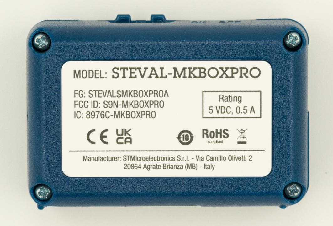
S9N-MKBOXPRO
Jul 25, 2023Development kit and reference design for prototyping and testing IoT applications. Key features core system board with sensors, ultra-low-power microcontroller, BLE wireless connectivity, optimized firmware libraries, cloud dashboard application.
Equipment Class
DTS - Digital Transmission System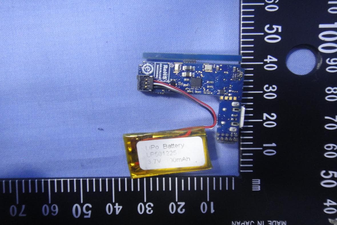
S9NWESU1
Dec 17, 2015Evaluation Board
Equipment Class
DTS - Digital Transmission System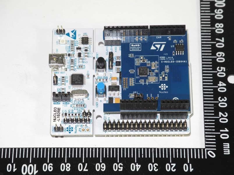
S9NIDB04A1
May 04, 2015Bluetooth Low energy expansion board based on BlueNRG for STM32 Nucleo
Equipment Class
DTS - Digital Transmission System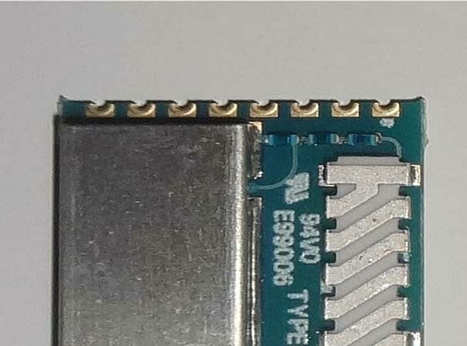
S9NSP1ML
Mar 03, 2014SPIRIT1 915 MHz Low Power RF Module
Equipment Class
DXT - Part 15 Low Power Transceiver, Rx Verified