S9NZB250AZigBee Module
ST Microelectronics S.R.L.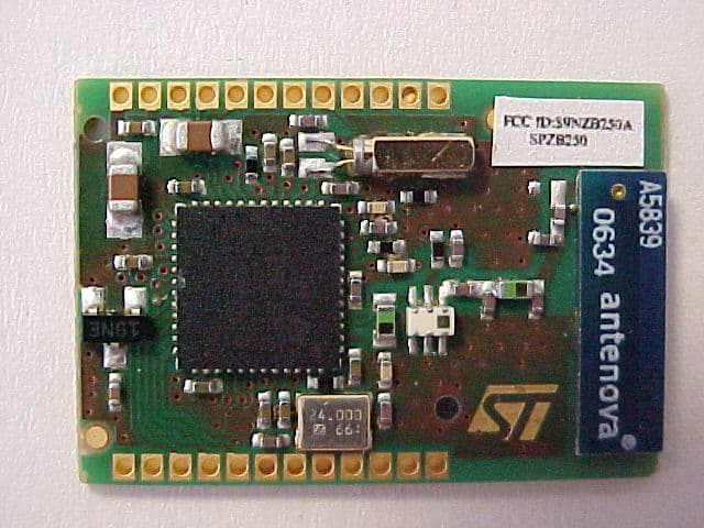
Click to zoom
Application Details
- Equipment Class
- DTS - Digital Transmission System
- Date of Grant
- Oct 24, 2007
- Application Purpose
- Original Equipment
- Date of Application
- Oct 24, 2007
- Equipment Note
- ZigBee Module
- Frequency Range
- 2405.00000000 - 2480.00000000
- Company
- ST Microelectronics S.R.L.
- Country
- Italy
Documents & Files
Document Text
Text extracted from the exhibit documents filed with the FCC. Open a document above to read the original.
Users Manual
September 2007 Rev 11/16 16 SPZB250 ZigBee module Features ■Integrated 2.4GHz ,IEEE 802,15,4-compliant transceiver – 0 dBm nominal TX output power – -92 dBm RX sensitivity – + 2 dBm in boost mode – RX filtering for co-existence with IEEE 802.11g and Bluetooth devices – Integrated VCO and loop filter ■Integrated IEEE 802.15.4 PHY and MAC ■128kB Embedded flash and 5kB integrated RAM for program and data storage ■17 GPIO with alternate functions: –GPIOs –UART –I 2 C –SPI –ADC ■2 16-bit general purpose timers; one 16-bit sleep timer ■ADC , sigma-delta converter with 12 bit resolution ■On board 24 MHz stable Xtal ■Selectable integrated RC oscillator ( typ 10KHz) or 32.768kHz Xtal for low power operation ■1 μA power consumption in deep sleep mode ■Watchdog timer and power on reset ■Pins available for Non-intrusive debug interface (SIF) ■Single supply voltage 2.1 to 3.6 Vdc ■CE compliant ■FCC compliant ( FCC ID:S9NZB250A ) Applications ■Industrial controls ■Sensor networking ■Monitoring of remote systems ■Home applications ■Security systems ■Lighting controls Description SPZB250 is a low power consumption ZigBee module based on SN250 ZigBee Network Processor which integrates a 2.4GHz, IEEE 802.15.4-compliant transceiver as well as IEEE 802.15.4 PHY and MAC. It enables OEMs to easily add wireless networking capability to any electronic device. Such a module is a very comprehensive solution to build sensors with meshing and self healing capability as required in a WSN scenario. 24 MHz high stability Xtal is available aboard the module to perform the timing requirements as per ZigBee specifications. An additional 32.768 kHz Xtal is provided for low power operation. A single supply voltage is requested to power the module. An integrated 2.5 GHz specific Murata antenna is aboard. The voltage supply also determines the I/O ports level allowing an easy interface with the host system. 128k flash and 5kbytes of static RAM are available for data and program storage. To support user defined applications, a number of peripherals such as GPIO,UART,I2C, ADC and general purpose timers are available and user selectable. The deep sleep mode with power consumption of less than 1 uA allows applications where the battery life is a key point. ( for other information and details, please refer to SN250 Datasheet available at www.st.com ) www.st.com ContentsSPZB250 2/16 Contents 1Block diagram . . . . . . . . . . . . . . . . . . . . . . . . . . . . . . . . . . . . . . . . . . . . . . 3 2Pin settings . . . . . . . . . . . . . . . . . . . . . . . . . . . . . . . . . . . . . . . . . . . . . . . . 3 2.1Pin connections . . . . . . . . . . . . . . . . . . . . . . . . . . . . . . . . . . . . . . . . . . . . . 3 2.2Pin description . . . . . . . . . . . . . . . . . . . . . . . . . . . . . . . . . . . . . . . . . . . . . . 4 3Maximum ratings . . . . . . . . . . . . . . . . . . . . . . . . . . . . . . . . . . . . . . . . . . . . 7 3.1Absolute maximum ratings . . . . . . . . . . . . . . . . . . . . . . . . . . . . . . . . . . . . . 7 3.2Operating ranges . . . . . . . . . . . . . . . . . . . . . . . . . . . . . . . . . . . . . . . . . . . . 7 4Electrical characteristics . . . . . . . . . . . . . . . . . . . . . . . . . . . . . . . . . . . . . 8 4.1DC electrical characteristics . . . . . . . . . . . . . . . . . . . . . . . . . . . . . . . . . . . . 8 4.2DC I/O specification . . . . . . . . . . . . . . . . . . . . . . . . . . . . . . . . . . . . . . . . . . 8 4.3RF electrical characteristics . . . . . . . . . . . . . . . . . . . . . . . . . . . . . . . . . . . . 9 5Mechanical dimensions . . . . . . . . . . . . . . . . . . . . . . . . . . . . . . . . . . . . . 10 Appendix A FCC statement . . . . . . . . . . . . . . . . . . . . . . . . . . . . . . . . . . . . . . . . . . 12 A.1Label instruction . . . . . . . . . . . . . . . . . . . . . . . . . . . . . . . . . . . . . . . . . . . . 13 A.2Special requirement for Modular application . . . . . . . . . . . . . . . . . . . . . . . 13 6Revision history . . . . . . . . . . . . . . . . . . . . . . . . . . . . . . . . . . . . . . . . . . . 15 SPZB250Block diagram 3/16 1 Block diagram Figure 1.Block diagram 2 Pin settings 2.1 Pin connections Figure 2.Pin connection diagram 24 MHz Xtal SN 2 5 0 Tranceiver Balun Filter Vdd SIF GPIO C ONTR SIGN RF antenna 32.768 kHz Xtal Pin settingsSPZB250 4/16 2.2 Pin description Table 1.Pin description Pin nPin nameDirectionDescription 1 GPIO6I/ODigital I/O ADC2AnalogADC input 2 TMR2CLKIExternal clock input of timer 2 TMR1ENMSKIExternal enable mask of timer1 2 GPIO5I/ODigital I/O ADC1AnalogADC Input 1 PTI_DATAOFrame signal of PTI (Packet Trace Interface) 3 GPIO4I/ODigital I/O ADC0AnalogADC Input 0 PTI_ENOFrame signal of PTI (Packet Trace Interface) 4 GPIO3I/ODigital I/O SSELISPI Master clock of Serial Controller SC2 TMR2IB.1ICapture of Input B of timer 1 5RSTBIActive low reset ( an internal pull-up of 30 kohm typ is provided) 6 GPIO11I/ODigital I/O CTSIUART CTS handshake of serial controller SC1 MCLKOSPI master clock of serial controller SC1 TMR2IA.1ICapture of Input A of timer 2 7 GPIO12I/ODigital I/O RTSOUART RTS handshake of serial controller SC1 TMR2IB.1ICapture of Input B of timer 2 8 GPIO0I/ODigital I/O MOSIOSPI master data out of serial controller SC2 MOSIISPI slave data in of serial controller SC2 TMR1IA.1ICapture of input A of timer 1 9 GPIO1I/ODigital I/O MISOISPI master data in of serial controller SC2 MISOOSPI slave data out of serial controller SC2 SDAI/OI2C data of serial controller SC2 TMR2IA.2ICapture of input A of timer 2 SPZB250Pin settings 5/16 Pin nPin nameDirectionDescription 10 GPIO2I/ODigital I/O MSCLKOSPI master clock of serial controller SC2 MSCLKISPI slave clock of serial controller SC2 SCLI/OI2C clock of serial controller SC2 TMR2IA.2ICapture of Input B of timer 2 11GND--Ground 12VDDPowerInput power supply 13 GPIO7I/ODigital I/O ADC3AnalogADC Input 3 REG_ENOExternal regulator open collector output 14 GPIO8I/ODigital I/O VREF_OUTAnalogA…
Text truncated - open the document above for the full version.
Block Diagram
SPZB250 ZigBee Module ZigBee RF MODULE BLOCK DIAGRAM
Cover Letter(s)
NOTICE: The results of tests and checks reported in this Test Report refer exclusively to the samples tested and described in the Report itself. This report shall not be reproduced partially or in its entirety without the written approval of IMQ S.p.A. IMQ S.p.A. - Via Quintiliano, 43 – I-20138 MILANO T E L E C O M M U N I C A T I O N S & T E L E M A T I C S F O R T R A N S P O R T S L A B O R A T O R Y Telecommunications & Telematics for Transports Lab. TEST REPORT Ref. No. ARSH00132/1 Date: 2007-09-25 According with: FCC Rules: Code of Federal Regulations (CFR) no. 47 – PART 15 – UNLICENSED MODULAR TRANSMITTER APPROVAL PUBLIC NOTICE: DA 00-1407 PRODUCT :ZigBee module general purpose TESTED MODEL :SPZB250 FCC ID :S9NZB250A APPLICANT : STMicroelectronics – Centro Direzionale Colleoni – Palazzo Andromeda 3 – I-20044 Agrate Brianza (MI) – ITALY MANUFACTURER: STMicroelectronics – Centro Direzionale Colleoni – Palazzo Andromeda 3 – I-20044 Agrate Brianza (MI) – ITALY TRADEMARK : STMicroelectronics OTHER INFORMATION Testing dates : 2007-07-19 ÷ 2007-07-20 Tested samples No. :1 Testing Laboratory : IMQ S.p.A. Via Quintiliano, 43 I-20138 MILANO Prepared by: R. Colombo (EMC and R&TTE Lab deputy) Signature: Revision Sheet Release No. Date Revision Description Rev. 0 2007-09-25 First emission TT&T Laboratory Test Report No. ARSH00132/1 Date: 2007-09-25 page 2 of 3 T E L E C O M M U N I C A T I O N S & T E L E M A T I C S F O R T R A N S P O R T S L A B O R A T O R Y REFERENCE STANDARDS According to : PUBLIC NOTICE : DA 00-1407 Part 15 Unlicensed Modular Transmitter Approval Released : June 26, 2000 MODULE-TYPE DEVICE APPROVAL OPTIONS: Modular Approval (MA) Limited Modular Approval (LMA) REQUIREMENTS The following requirements are fulfilled: 1) The modular transmitter must have its own RF shielding: The RF module fulfils the emission requirements of the FCC rules without additional shielding. 2) The modular transmitter must have buffered modulation/data inputs: The module has a memory management unit inside of the IC. The processor interfacing with the external application by means general purpose I/O ( GPIO) , Uart, SPI. The processor interfaces also the RF part of the module exchanging data and command with it. Inside the processor a flash memory is available to download the customer application and the ZigBee profiles. 3) The modular transmitter must have its own power supply regulation: The IC contains an own voltage regulation. In case of changes in the supply voltage VCC (for example caused by temperature changes or other effects), the internal voltage will be stabilized. 4) The modular transmitter must comply with the antenna requirements of Section 15.203 and 15.204: The end-user product will be installed in such a manner that only the authorized antenna is used. 5) The modular transmitter must be tested in a stand-alone configuration: The RF module was tested in a stand-alone configuration. TT&T Laboratory Test Report No. ARSH00132/1 Date: 2007-09-25 page 3 of 3 T E L E C O M M U N I C A T I O N S & T E L E M A T I C S F O R T R A N S P O R T S L A B O R A T O R Y 6) The modular transmitter must be labelled with its own FCC ID number: The RF module will be labelled with its own FCC ID number. When the module is installed inside the end-product, the label is not visible. The end- user/integrator is instructed how to apply the exterior label. 7) The modular transmitter must comply with any specific rule or operating requirements applicable to the transmitter and the manufacturer must provide adequate instructions along with the module to explain any such requirements: The EUT is compliant with all applicable FCC rules. Detail instructions are given in the product Users Guide. 8) The modular transmitter must comply with any applicable RF exposure requirements. •Maximum measured power output: 3,08 mW (4,89 dBm) •Maximum antenna gain: 0,6 dBi = numeric gain 1,148 (see also FCC test report) Maximum permissible exposure defined in 47 CFR 1.1310: 1 mW/cm². The distance from the EUT's transmitting antenna where the exposure level reaches the maximum permitted level is calculated using the general equation: S = P*G / 4JR² S max = 1 mW/cm² P= 4,89 mW G= 0,6 dBi = 1,148 (numeric gain) R= distance in cm Solving for R, the 1 mW/cm² limit is reached in a distance of 0,53 cm to the transmitting antenna. The RF module operates at low power level so it does not exceed the Commission’s RF exposure guidelines limits; furthermore, Spread spectrum transmitters operate according to the Section 15.247 are categorically excluded from routine environmental evaluation. Special requirement for Limited Modular Approval: The customer retain control over the final installation of the RF module. The EUT is approved only for use when installed in device produced by the manufacturer (Grantee).
Operational Description
SPZB250 ZigBee Module ZigBee RF MODULE OPERATIONAL DESCRIPTION SPZB250 is a ZigBee module optimized for embedded applications. It enables OEMs to easily add short-range radio link between electronic devices. The module is based on SN250 ZigBee Netework Processor which integrates a 2.4GHz, IEEE 802.15.4-compliant transceiver as well as IEEE 802.15.4 PHY and MAC. A24 MHz high stability Xtal is present on board to guarantee the required timing imposed by ZigBee specifications; additionally a 32.768kHz Xtal is provided for low power operation. A 128kB of embedded flash memory and 5kB of RAM is available for data and program storage. To support user defined applications, a number of peripherals such as GPIO,UART,I2C, ADC and general purpose timers are available and user selectable. A single supply voltage is foreseen; an internal voltage regulator supply the different block of the system; the voltage supply fixes also the I/O ports levels allowing an easy interface with the host system. The deep sleep mode with power consumption of less than 1 uA allows applications where the battery life is a key point. APPLICATIONS •Industrial controls •Sensor Networking •Monitoring of remote systems •Home applications •Security systems •Lighting controls FEATURES •Integrated 2.4GHz ,IEEE 802,15,4-compliant transceiver •Integrated IEEE 802.15.4 PHY and MAC •128kB Embedded flash and 5kB integrated RAM for program and data storage •17 GPIO with alternate functions (GPIOs, UART, I2C, SPI, ADC) •2 16-bit general purpose timers; one 16-bit sleep timer •ADC , sigma-delta converter with 12 bit resolution •On board 24 MHz stable Xtal •Selectable Integrated RC oscillator ( typ 10KHz) or 32.768kHz Xtal for low power operation •1 uA power consumption in Deep sleep mode •Watchdog timer and power on reset •Pins available for Non-intrusive debug interface (SIF) •Single voltage supply
Test Report
NOTICE: The results of tests and checks reported in this Test Report refer exclusively to the samples tested and described in the Report itself. This report shall not be reproduced partially or in its entirety without the written approval of IMQ S.p.A. IMQ S.p.A. - Via Quintiliano, 43 – I-20138 MILANO Telecommunications & Telematics for Transports Lab. TEST REPORT Ref. No. ARSH00132 Date: 2007-07-26 Measurements performed in accordance with: FCC Rules : Code of Federal Regulations (CFR) no. 47 - PART 15 – RADIO FREQUENCY DEVICES PRODUCT : ZigBee module general purpose TESTED MODEL : SPZB250 FCC ID : S9NZB250A APPLICANT : STMicroelectronics – Centro Direzionale Colleoni – Palazzo Andromeda 3 – I-20044 Agrate Brianza (MI) - ITALY MANUFACTURER : STMicroelectronics – Centro Direzionale Colleoni – Palazzo Andromeda 3 – I-20044 Agrate Brianza (MI) - ITALY TRADEMARK : STMicroelectronics OTHER INFORMATION Testing dates : 2007-07-19 ÷ 2007-07-20 Tested samples No. : 2 Testing Laboratory : IMQ S.p.A. Via Quintiliano, 43 I-20138 MILANO Tested by : R. Radice Signature: Date : 2007-07-26 Checked by: R. Colombo (EMC and R&TTE Lab. Deputy) Signature: Date : 2007-07-26 Revision Sheet Release No. Date Revision Description Rev. 0 2007-07-26 Test Results and Evaluation Report T ELECOMMUNICATIONS & T ELEMATICS FOR T RANSPORTS L ABORATORY TT&T Laboratory Test Report No. ARSH00132 Date 2007-07-26 page 2 of 49 T ELECOMMUNICATIONS & T ELEMATICS FOR T RANSPORTS L ABORATORY CONTENTS 1 General Description of Equipment under Test ........................ 1-3 1.1 APPLICANT............................................................................... 1-3 1.2 MANUFACTURER..................................................................... 1-3 1.3 EQUIPMENT CLASSIFICATION ............................................... 1-3 1.4 BASIC DESCRIPTION OF EQUIPMENT UNDER TEST........... 1-4 1.5 FEATURE OF EQUIPMENT UNDER TEST .............................. 1-5 2 Test Configuration of Equipment under Test .......................... 2-7 2.1 ENVIRONMENTAL CONDITIONS ............................................ 2-7 2.2 DESCRIPTION OF SUPPORT EQUIPMENT............................ 2-7 2.3 INTERFACE IDENTIFICATION AND CONNECTION DIAGRAM OF TEST SYSTEM .......................................................................... 2-8 3 Operation of Equipment under Test ......................................... 3-9 3.1 OPERATING TEST CONDITIONS ............................................ 3-9 4 Tests Identification and Results ............................................. 4-10 4.1 METHODS OF MEASUREMENT............................................ 4-12 4.2 FREQUENCY RANGE INVESTIGATED ................................. 4-12 5 Measurements and Tests Data................................................ 5-13 6 Additional Technical Information ........................................... 6-42 6.1 ELECTROMAGNETICALLY RELEVANT COMPONENTS: ..... 6-42 6.2 RFI SUPPRESSION DEVICES:.............................................. 6-42 6.3 EMI PROTECTION DEVICES:................................................ 6-42 7 Technical Documentation........................................................ 7-43 8 Photographic Documentation ................................................. 8-44 8.1 EUT IDENTIFICATION ............................................................ 8-44 8.2 TEST SET-UP ......................................................................... 8-47 9 Measurement and Test Equipment Instrumentation ............. 9-49 TT&T Laboratory Test Report No. ARSH00132 Date 2007-07-26 page 3 of 49 T ELECOMMUNICATIONS & T ELEMATICS FOR T RANSPORTS L ABORATORY 1 GENERAL DESCRIPTION OF EQUIPMENT UNDER TEST 1.1 APPLICANT NAME STMicroelectronics ADDRESS Centro Direzionale Colleoni – Palazzo Andromeda 3 – I-20044 Agrate Brianza (MI) COUNTRY ITALY 1.2 MANUFACTURER NAME STMicroelectronics ADDRESS Centro Direzionale Colleoni – Palazzo Andromeda 3 – I-20044 Agrate Brianza (MI) COUNTRY ITALY 1.3 EQUIPMENT CLASSIFICATION According to the definition 15.3 (o) EUT is a Intentional Radiator operating within the bands 2400-2483,5 MHz so it shall fulfil provisions of 47CFR Part 15 Subpart C – Intentional radiators – and Section 15.247. TT&T Laboratory Test Report No. ARSH00132 Date 2007-07-26 page 4 of 49 T ELECOMMUNICATIONS & T ELEMATICS FOR T RANSPORTS L ABORATORY 1.4 BASIC DESCRIPTION OF EQUIPMENT UNDER TEST Parameters Value Type of equipment : ZigBee module general purpose Model : SPZB250 FCC ID. : S9NZB250A Trade Name STMicroelectronics Data cable : / Telecom cable : / Power supply type : DC 3.3V, 41,5mA max. AC power input cable : / DC power input cable : / TT&T Laboratory Test Report No. ARSH00132 Date 2007-07-26 page 5 of 49 T ELECOMMUNICATIONS & T ELEMATICS FOR T RANSPORTS L ABORATORY 1.5 FEATURE OF EQUIPMENT UNDER TEST Power specification 3.3 V dc Operating frequency: 2405 ÷ 2480 MHz (16 Channels) Maximum RF output power: < 1 W Modulation: O-QPSK Channel Spacing: >1 MHz Antenna: Dedicated antenna (0,6 dBi gain) integrated in the test jig RX sensitivity: -92 dBm Main SW identification / Main HW Board identification / Peripherals included (for system application) None Interfaces : None Integrated interfaces : None AC adapter: None TT&T Laboratory Test Report No. ARSH00132 Date 2007-07-26 page 6 of 49 T ELECOMMUNICATIONS & T ELEMATICS FOR T RANSPORTS L ABORATORY CHANNEL CONFIGURATION Channel (No.) Frequency (MHz) 11 2405.00 12 2410.00 13 2415.00 14 2420.00 15 2425.00 16 2430.00 17 2435.00 18 2440.00 19 2445.00 20 2450.00 21 2455.00 22 2460.00 23 2465.00 24 2470.00 25 2475.00 26 2480.00 TT&T Laboratory Test Report No. ARSH00132 Date 2007-07-26 page 7 of 49 T ELECOMMUNICATIONS & T ELEMATICS FOR T RANSPORTS L ABORATORY 2 TEST CONFIGURATION OF EQUIPMENT UNDER TEST 2.1 ENVIRONMENTAL CONDITIONS TEST CONDITIONSMEASURED Ambient Temperature 20 ÷ 25 °C Relative Humidity 50 ÷ 60 % Atmospheric Pressure 900 ÷ 1000 mbar 2.2 DESCRIPTI…
Text truncated - open the document above for the full version.
Contact Information
Applicant
Nunzio Dipaola(Application Manager)
Test Firm
IMQ - Istituto Italiano Marchio QualitaVincenzo La Fragola
Technical Specifications
| # | Rule Parts | Frequency Range | Power Output |
|---|---|---|---|
| 1 | 15C | 2.40 GHz - 2.48 GHz | 3.00 mW |
Other Applications from ST Microelectronics S.R.L.
S9N-ST87M01
Dec 11, 2025Module for NB-IOT NB2 and GNSS
Equipment Class
PCB - PCS Licensed Transmitter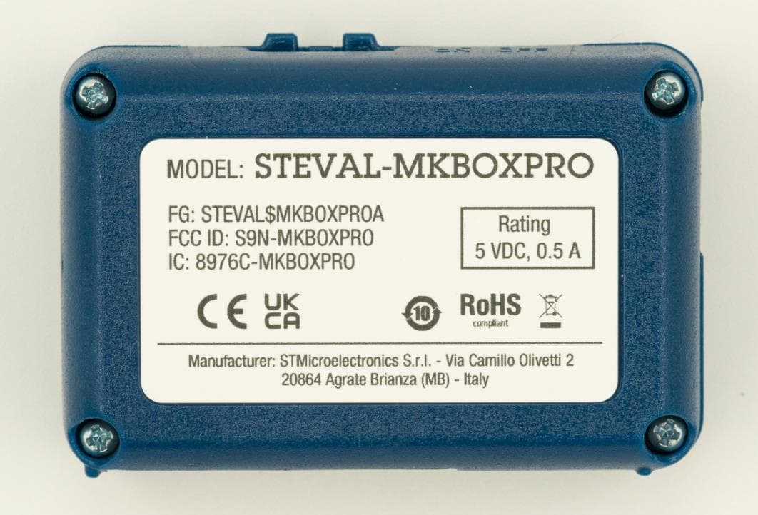
S9N-MKBOXPRO
Jul 25, 2023Development kit and reference design for prototyping and testing IoT applications. Key features core system board with sensors, ultra-low-power microcontroller, BLE wireless connectivity, optimized firmware libraries, cloud dashboard application.
Equipment Class
DTS - Digital Transmission System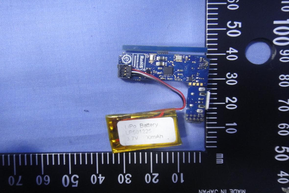
S9NWESU1
Dec 17, 2015Evaluation Board
Equipment Class
DTS - Digital Transmission System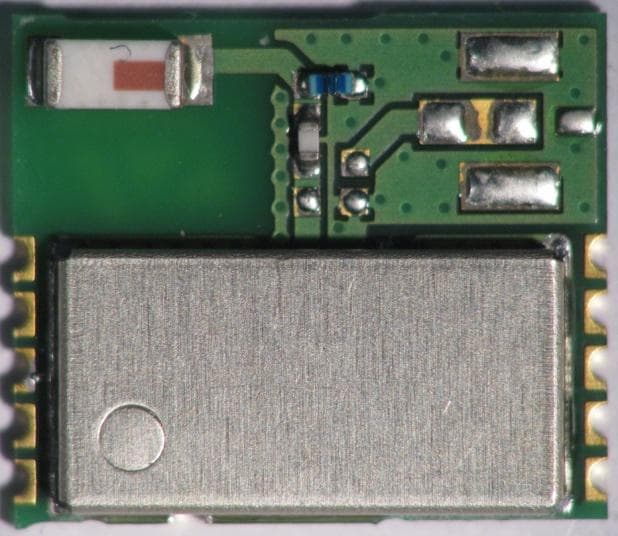
S9NSPBTLERF
May 24, 2015SPBTLE-RF Bluetooth Low Energy Module
Equipment Class
DTS - Digital Transmission System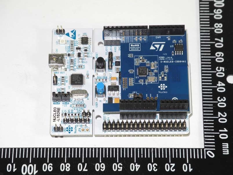
S9NIDB04A1
May 04, 2015Bluetooth Low energy expansion board based on BlueNRG for STM32 Nucleo
Equipment Class
DTS - Digital Transmission System