S9NZB32C1SPZB32Wxy1.z series IEE802.15.4 / ZigBee� Module
ST Microelectronics S.R.L.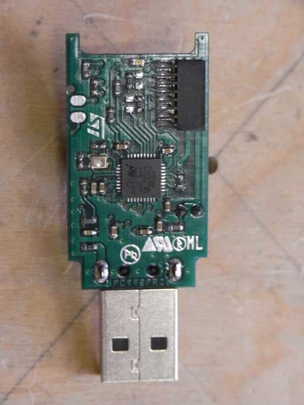
Click to zoom
Application Details
- Equipment Class
- DTS - Digital Transmission System
- Date of Grant
- Nov 03, 2011
- Application Purpose
- Original Equipment
- Date of Application
- Nov 02, 2011
- Equipment Note
- SPZB32Wxy1.z series IEE802.15.4 / ZigBee� Module
- Frequency Range
- 2405.00000000 - 2480.00000000
- Company
- ST Microelectronics S.R.L.
- Country
- Italy
Documents & Files
Document Text
Text extracted from the exhibit documents filed with the FCC. Open a document above to read the original.
Users Manual
D RA FT 28 July 2011Doc ID xxxxx Rev 11/19 19 SPZB32Wxy1.z 802.15.4 ZigBee ® modules based on the STM32W chipset Features ■2.4 GHz IEEE 802.15.4-compliant SMD modules based on the ST STM32W chipset solution featuring: – Integrated 2.4 GHz transceiver – PHY and MAC IEEE 802.15.4 features – Integrated ARM ® Cortex-M3 core – Integrated embedded Flash and RAM – Integrated encryption (AES-128) accelerator ■Power amplified RF performances: – Up to 20 dBm nominal TX output power – Up to 105 dBm RX sensitivity ■Robust Wi-Fi and Bluetooth ® coexistence ■16 channels (IEEE 802.15.4 channel 11 to 26) ■Multiple configurable interfaces available (UART, SPI, I2C, ADC, GPIOs) ■Industry standard JTAG programming ■Onboard 24 MHz and 32.768 kHz stable Xtal ■Less than 2 uA typ power consumption in deep sleep mode (32.768 Xtal) ■Multiple antenna options: integrated antenna or integrated UFL connector ■Multiple Protocol Stack Options ■Single voltage supply (2.1 to 3.6 V) ■FCC and CE compliant qualified ■Small Form Factor : 16.4 x 26.5 mm ■Operating temperature range: -40 °C to +85 °C www.st.com D RA FT ContentsSPZB32Wxy1.z 2/19 Doc ID xxxxx Rev 1 Contents 1Description . . . . . . . . . . . . . . . . . . . . . . . . . . . . . . . . . . . . . . . . . . . . . . . . . 3 2RoHS compliance . . . . . . . . . . . . . . . . . . . . . . . . . . . . . . . . . . . . . . . . . . . 4 3Application . . . . . . . . . . . . . . . . . . . . . . . . . . . . . . . . . . . . . . . . . . . . . . . . . 4 4Block diagram . . . . . . . . . . . . . . . . . . . . . . . . . . . . . . . . . . . . . . . . . . . . . . 5 5Pin settings . . . . . . . . . . . . . . . . . . . . . . . . . . . . . . . . . . . . . . . . . . . . . . . . 6 5.1Pin connections . . . . . . . . . . . . . . . . . . . . . . . . . . . . . . . . . . . . . . . . . . . . . 6 5.2Pin description . . . . . . . . . . . . . . . . . . . . . . . . . . . . . . . . . . . . . . . . . . . . . . 7 6Electrical characteristics . . . . . . . . . . . . . . . . . . . . . . . . . . . . . . . . . . . . 11 6.1Absolute maximum ratings . . . . . . . . . . . . . . . . . . . . . . . . . . . . . . . . . . . . 11 6.2Recommended operating conditions . . . . . . . . . . . . . . . . . . . . . . . . . . . . 11 6.3DC electrical characteristics . . . . . . . . . . . . . . . . . . . . . . . . . . . . . . . . . . . 11 6.4Digital I/O specifications . . . . . . . . . . . . . . . . . . . . . . . . . . . . . . . . . . . . . . 12 6.5RF electrical characteristics . . . . . . . . . . . . . . . . . . . . . . . . . . . . . . . . . . . 12 7Mechanical dimensions . . . . . . . . . . . . . . . . . . . . . . . . . . . . . . . . . . . . . 13 8Soldering . . . . . . . . . . . . . . . . . . . . . . . . . . . . . . . . . . . . . . . . . . . . . . . . . 14 9Product approvals . . . . . . . . . . . . . . . . . . . . . . . . . . . . . . . . . . . . . . . . . . 15 9.1FCC approvals . . . . . . . . . . . . . . . . . . . . . . . . . . . . . . . . . . . . . . . . . . . . . 15 9.1.1FCC labeling requirements . . . . . . . . . . . . . . . . . . . . . . . . . . . . . . . . . . 16 9.2European certification . . . . . . . . . . . . . . . . . . . . . . . . . . . . . . . . . . . . . . . 16 10Ordering information scheme . . . . . . . . . . . . . . . . . . . . . . . . . . . . . . . . 17 11Revision history . . . . . . . . . . . . . . . . . . . . . . . . . . . . . . . . . . . . . . . . . . . 18 SPZB32Wxy1.zDescription Doc ID xxxxx Rev 13/19 D RA FT 1 Description SPZB32Wxy1.z is a series of ready-to-use IEEE 802.15.4/ZigBee compliant and power amplified RF modules optimized for embedded applications that require low data rate communications and high transmission range capabilities based on the STM32W single chip that integrates a 2.4 GHz, IEEE 802.15.4-compliant transceiver together with an ARM® Cortex embedded processor . The modules are very compact and enable OEMs to easily add wireless capabilities to electronics devices by optimizing time-to-market, cost, size, and consumption of their target applications. No RF experience or expertise is required to add this powerful networking capability to the final product. 24 MHz high stability Xtal is available aboard the modules to perform the timing requirements as per IEEE 802.15.4/ZigBee® specifications; additionally a 32.768kHz Xtal is also provided onboard for low power operation. A single supply voltage is requested to power the modules. The supply is in the range of 2.1 to 3.6 V. The voltage supply also determines the I/O ports level allowing an easy interface with additional peripherals. An advanced solution integrating PA and LNA in a single package is aboard to ensure excellent power transmission and receiver sensitivity performances. To support user defined applications, a number of peripherals such as GPIO, UART, I2C, ADC and general purpose timers are available and user selectable. The size and footprint of this series of modules is equivalent to that of the series SPZB32Wxy2.z to facilitate the evaluation of the different range options on the target application. The series groups multiple versions that differ in terms of memory size , antenna (ceramic antenna or integrated u.fl connector for the connection of an external antenna) and stacks options (ZigBee, RF4CE, SimpleMAC). The SPZB32W1y1.z versions are based on the STM32W108CB chipset integrating 128 kB of embedded flash memory and 8 kB of RAM available for data and program storage. For technical details on the STM32W108CB chipset refer to the related datasheet. For technical details on the supported stacks refer to the related user guide and application notes. D RA FT RoHS complianceSPZB32Wxy1.z 4/19 Doc ID xxxxx Rev 1 2 RoHS compliance ST modules are RoHS compliant and comply with ECOPACK ® norms. 3 Application ●Smart energy applications ●Machine2Machine industrial control ●Wireless sensor networks ●Home/building automation ●Smart appliances ●Wireless alarms and security systems ●Lighting control ●Remote monitoring SPZB32Wxy1.zBlock diagra…
Text truncated - open the document above for the full version.
Block Diagram
Prepared: A. Rizzoli Checked: Design ref.: File: SPZB32Wxy1_z - Block Diagram & behavior.DOC Date: 29/09/11 Rev.: 1.0 IMS - Subsystem Product Group / R&D Title: SPZB32Wxy1.z module 9/29/2011 1 / 2 SPZB32W1A1.1 / SPZB32W1C1.1 IEEE 802.15.4 ZigBee module and SPZB32Wxy1.z family BLOCK DIAGRAM and behavior Modules SPZB32W1A1.1 / SPZB32W1C1.1 and in general modules belonging to the family SPZB32Wxy1.z are based on the same hardware and the only difference is the use of an integrated antenna or a specified external antenna. The block diagram are therefore the following: System Signals (RESET , etc.) 32.768 kHz XTAL24 MHz XTAL STM32W108CB Microcontroller & Peripheral (TRANSCEIVER) SIGE-SE2432L Front-End RF circuit RF antenna Vdd GPIO SPI / UART RF FILTER (harmonics) SPZB32W1A1.1 & SPZB32WxA1.z block diagram System Signals (RESET , etc.) 32.768 kHz XTAL24 MHz XTAL STM32W108CB Microcontroller & Peripheral (TRANSCEIVER) SIGE-SE2432L Front-End RF circuit RF antenna Vdd GPIO SPI / UART RF FILTER (harmonics) SPZB32W1C1.1 & SPZB32WxC1.z block diagram The modules are based on the STM32W108 IC which is the core of the product ; it has integrated inside the IEEE 802.15.4 Phy and Mac to allow applications based on IEEE 802.15.4 standard ( ZigBee, SimpleMac,.....). As the output power of STM32W108 is limited an external power amplifier (PA) ( Sige SE2432L) has been added to get the desired output power of typically 18 dBm. After the PA has been put a filter to limits the unwanted harmonics. Two Xtals are provided on the module The 24 MHz oscillator is used to get the machine microcontroller main clock and also, after the proper internal PLL circuit, to get the fundamentals TX / RX frequencies carriers (starting from 2405 MHz to 2480 MHz with 5 MHz step, according to the IEEE802.15.4 standard). Prepared: A. Rizzoli Checked: Design ref.: File: SPZB32Wxy1_z - Block Diagram & behavior.DOC Date: 29/09/11 Rev.: 1.0 IMS - Subsystem Product Group / R&D Title: SPZB32Wxy1.z module 9/29/2011 2 / 2 The 32.768 kHz oscillator is used by the module microcontroller to reduce the power consumption during the power states. Module behavior: The module can be seen as a peripheral dedicated to the IEEE802.15.4 standard and in particular to ZigBee , SimpleMAC ,RF4CE protocol stack. Once the module is powered on , it make available its resources and in particular the main interface which can be SPI,UART,I2C port. By means this port the user host is able to control the functionality of the module; that means the host can decide in which way the module has to work: - make the network - join the network - transmit data - receive data, - ..... For example : - if data must be transmitted , the module will receive to data from the host , it will pack the data according to the IEEE802.15.4 and driving properly the PA it will send the data. - when data is received by the module, an interrupt is generated and the host can get the data from the module through the main port. Some extra pins are provided on the module as : Reset to reset the module , JTAG to debug the module.
ID Label/Location Info
TITLE: SPZB32W1A1.1 COMPONENTS LAYOUT 1. PURPOSE This document template can be used for : COMMERCIAL PRODUCT CODE FINISHED GOOD CODEASSY & TEST PLANTRAW LINE CODE TECHNICAL CODE SPZB32W1A1.1 SPZB32W1A1.1$ 6483 (Bouskoura) HBIC*ZBIC027 HBIC ZBIC027 2. SCOPE Site : Assy & Test Plant. (See Table) Operation : Component assembly for ZIGBEE STM32W CLASS 1 Product : SPZB32W1A1.1. PCB ref.: PC06A Area : Manufacturing. 3. REFERENCE DOCUMENTS 3.1 ADCS reference documents For ADCS references see “REFERENCES” on Cover page C. 4. DEFINITIONS ¾ PCB : Printed Circuit Board. ¾ SMD : Surface Mounting Device. 5. GENERAL: N/A 6. SAFETY REQUIREMENTS: N/A 7. PROCEDURE This document is needed to show the components layout to be soldered onto PCB of the product in subject with possible remarks and/or assembly sequence useful to Manufacturing plant. Refer to next page(s). 8. QUALITY REQUIREMENTS: N/A 9. ENVIRONMENTAL / ECOLOGICAL REQUIREMENTS (STMicroelectronics recommends viewing documents on the screen rather than printing to limit paper consumption.) DOCUMENT 8337038REVISION ANOT AN APPROVED DOCUMENT (Check latest revision)DATE 15-JUN-2011page: 1/2 ©Copyright STMicroelectronicsCOMPANY INTERNALUnauthorized reproduction and communication strictly prohibited DOCUMENT 8337038REVISION ANOT AN APPROVED DOCUMENT (Check latest revision)DATE 15-JUN-2011page: 2/2 ©Copyright STMicroelectronicsCOMPANY INTERNALUnauthorized reproduction and communication strictly prohibited
Operational Description
D RA FT 28 July 2011Doc ID xxxxx Rev 11/19 19 SPZB32Wxy1.z 802.15.4 ZigBee ® modules based on the STM32W chipset Features ■2.4 GHz IEEE 802.15.4-compliant SMD modules based on the ST STM32W chipset solution featuring: – Integrated 2.4 GHz transceiver – PHY and MAC IEEE 802.15.4 features – Integrated ARM ® Cortex-M3 core – Integrated embedded Flash and RAM – Integrated encryption (AES-128) accelerator ■Power amplified RF performances: – Up to 20 dBm nominal TX output power – Up to 105 dBm RX sensitivity ■Robust Wi-Fi and Bluetooth ® coexistence ■16 channels (IEEE 802.15.4 channel 11 to 26) ■Multiple configurable interfaces available (UART, SPI, I2C, ADC, GPIOs) ■Industry standard JTAG programming ■Onboard 24 MHz and 32.768 kHz stable Xtal ■Less than 2 uA typ power consumption in deep sleep mode (32.768 Xtal) ■Multiple antenna options: integrated antenna or integrated UFL connector ■Multiple Protocol Stack Options ■Single voltage supply (2.1 to 3.6 V) ■FCC and CE compliant qualified ■Small Form Factor : 16.4 x 26.5 mm ■Operating temperature range: -40 °C to +85 °C www.st.com D RA FT ContentsSPZB32Wxy1.z 2/19 Doc ID xxxxx Rev 1 Contents 1Description . . . . . . . . . . . . . . . . . . . . . . . . . . . . . . . . . . . . . . . . . . . . . . . . . 3 2RoHS compliance . . . . . . . . . . . . . . . . . . . . . . . . . . . . . . . . . . . . . . . . . . . 4 3Application . . . . . . . . . . . . . . . . . . . . . . . . . . . . . . . . . . . . . . . . . . . . . . . . . 4 4Block diagram . . . . . . . . . . . . . . . . . . . . . . . . . . . . . . . . . . . . . . . . . . . . . . 5 5Pin settings . . . . . . . . . . . . . . . . . . . . . . . . . . . . . . . . . . . . . . . . . . . . . . . . 6 5.1Pin connections . . . . . . . . . . . . . . . . . . . . . . . . . . . . . . . . . . . . . . . . . . . . . 6 5.2Pin description . . . . . . . . . . . . . . . . . . . . . . . . . . . . . . . . . . . . . . . . . . . . . . 7 6Electrical characteristics . . . . . . . . . . . . . . . . . . . . . . . . . . . . . . . . . . . . 11 6.1Absolute maximum ratings . . . . . . . . . . . . . . . . . . . . . . . . . . . . . . . . . . . . 11 6.2Recommended operating conditions . . . . . . . . . . . . . . . . . . . . . . . . . . . . 11 6.3DC electrical characteristics . . . . . . . . . . . . . . . . . . . . . . . . . . . . . . . . . . . 11 6.4Digital I/O specifications . . . . . . . . . . . . . . . . . . . . . . . . . . . . . . . . . . . . . . 12 6.5RF electrical characteristics . . . . . . . . . . . . . . . . . . . . . . . . . . . . . . . . . . . 12 7Mechanical dimensions . . . . . . . . . . . . . . . . . . . . . . . . . . . . . . . . . . . . . 13 8Soldering . . . . . . . . . . . . . . . . . . . . . . . . . . . . . . . . . . . . . . . . . . . . . . . . . 14 9Product approvals . . . . . . . . . . . . . . . . . . . . . . . . . . . . . . . . . . . . . . . . . . 15 9.1FCC approvals . . . . . . . . . . . . . . . . . . . . . . . . . . . . . . . . . . . . . . . . . . . . . 15 9.1.1FCC labeling requirements . . . . . . . . . . . . . . . . . . . . . . . . . . . . . . . . . . 16 9.2European certification . . . . . . . . . . . . . . . . . . . . . . . . . . . . . . . . . . . . . . . 16 10Ordering information scheme . . . . . . . . . . . . . . . . . . . . . . . . . . . . . . . . 17 11Revision history . . . . . . . . . . . . . . . . . . . . . . . . . . . . . . . . . . . . . . . . . . . 18 SPZB32Wxy1.zDescription Doc ID xxxxx Rev 13/19 D RA FT 1 Description SPZB32Wxy1.z is a series of ready-to-use IEEE 802.15.4/ZigBee compliant and power amplified RF modules optimized for embedded applications that require low data rate communications and high transmission range capabilities based on the STM32W single chip that integrates a 2.4 GHz, IEEE 802.15.4-compliant transceiver together with an ARM® Cortex embedded processor . The modules are very compact and enable OEMs to easily add wireless capabilities to electronics devices by optimizing time-to-market, cost, size, and consumption of their target applications. No RF experience or expertise is required to add this powerful networking capability to the final product. 24 MHz high stability Xtal is available aboard the modules to perform the timing requirements as per IEEE 802.15.4/ZigBee® specifications; additionally a 32.768kHz Xtal is also provided onboard for low power operation. A single supply voltage is requested to power the modules. The supply is in the range of 2.1 to 3.6 V. The voltage supply also determines the I/O ports level allowing an easy interface with additional peripherals. An advanced solution integrating PA and LNA in a single package is aboard to ensure excellent power transmission and receiver sensitivity performances. To support user defined applications, a number of peripherals such as GPIO, UART, I2C, ADC and general purpose timers are available and user selectable. The size and footprint of this series of modules is equivalent to that of the series SPZB32Wxy2.z to facilitate the evaluation of the different range options on the target application. The series groups multiple versions that differ in terms of memory size , antenna (ceramic antenna or integrated u.fl connector for the connection of an external antenna) and stacks options (ZigBee, RF4CE, SimpleMAC). The SPZB32W1y1.z versions are based on the STM32W108CB chipset integrating 128 kB of embedded flash memory and 8 kB of RAM available for data and program storage. For technical details on the STM32W108CB chipset refer to the related datasheet. For technical details on the supported stacks refer to the related user guide and application notes. D RA FT RoHS complianceSPZB32Wxy1.z 4/19 Doc ID xxxxx Rev 1 2 RoHS compliance ST modules are RoHS compliant and comply with ECOPACK ® norms. 3 Application ●Smart energy applications ●Machine2Machine industrial control ●Wireless sensor networks ●Home/building automation ●Smart appliances ●Wireless alarms and security systems ●Lighting control ●Remote monitoring SPZB32Wxy1.zBlock diagra…
Text truncated - open the document above for the full version.
Test Report
T&TT Laboratory Test Report No. ARSL00124 Date 2011-10-06 page 2 of 77 T ELECOMMUNICATIONS & T ELEMATICS FOR T RANSPORTS L ABORATORY CONTENTS 1 General Description of Equipment under Test ........................ 1-3 1.1 APPLICANT............................................................................... 1-3 1.2 MANUFACTURER..................................................................... 1-3 1.3 EQUIPMENT CLASSIFICATION ............................................... 1-3 1.4 BASIC DESCRIPTION OF EQUIPMENT UNDER TEST ..........1-4 1.5 FEATURE OF EQUIPMENT UNDER TEST.............................. 1-5 2 Test Configuration of Equipment under Test .......................... 2-7 2.1 ENVIRONMENTAL CONDITIONS ............................................ 2-7 2.2 DESCRIPTION OF SUPPORT EQUIPMENT............................ 2-7 2.3 INTERFACE IDENTIFICATION AND CONNECTION DIAGRAM OF TEST SYSTEM.......................................................................... 2-8 3 Operation of Equipment under Test ......................................... 3-9 3.1 OPERATING TEST CONDITIONS ............................................ 3-9 4 Tests Identification and Results ............................................. 4-10 4.1 METHODS OF MEASUREMENT ............................................ 4-12 4.2 FREQUENCY RANGE INVESTIGATED ................................. 4-12 5 Measurements and Tests Data................................................ 5-13 6 Additional Technical Information............................................ 6-67 6.1 ELECTROMAGNETICALLY RELEVANT COMPONENTS: .... 6-67 6.2 RFI SUPPRESSION DEVICES: .............................................. 6-67 6.3 EMI PROTECTION DEVICES: ................................................ 6-67 7 Technical Documentation........................................................ 7-68 8 Photographic Documentation ................................................. 8-69 8.1 EUT IDENTIFICATION ............................................................ 8-69 8.2 TEST SET-UP ......................................................................... 8-74 9 Measurement and Test Equipment Instrumentation............. 9-77 T&TT Laboratory Test Report No. ARSL00124 Date 2011-10-06 page 3 of 77 T ELECOMMUNICATIONS & T ELEMATICS FOR T RANSPORTS L ABORATORY 1 GENERAL DESCRIPTION OF EQUIPMENT UNDER TEST 1.1 APPLICANT NAME STMicroelectronics ADDRESS Via C. Olivetti, 2 – I-20041 Agrate Brianza (MI) COUNTRY ITALY 1.2 MANUFACTURER NAME STMicroelectronics ADDRESS Via C. Olivetti, 2 – I-20041 Agrate Brianza (MI) COUNTRY ITALY 1.3 EQUIPMENT CLASSIFICATION According to the definition 15.3 (o) EUT is a Intentional Radiator operating within the bands 2400-2483,5 MHz so it shall fulfil provisions of 47CFR Part 15 Subpart C – Intentional radiators – and Section 15.247. T&TT Laboratory Test Report No. ARSL00124 Date 2011-10-06 page 4 of 77 T ELECOMMUNICATIONS & T ELEMATICS FOR T RANSPORTS L ABORATORY 1.4 BASIC DESCRIPTION OF EQUIPMENT UNDER TEST Parameters Value Type of equipment : ZigBee module general purpose Model: SPZB32W1A1.1 SPZB32W1C1.1 FCC ID. : S9NZB32C1 Trade Name: STMicroelectronics Data cable : / Telecom cable : / Power supply type : DC 3.3V AC power input cable : / DC power input cable : / Model Description SPZB32W1C1.1 Provided with external ANTENOVA Antenna connected with RF reverse SMA connector SPZB32W1A1.1 Provided with integrated RAINSUN Antenna Remark: Between the two models no changes to the basic frequency determining and stabilizing circuitry (including clock and data rates), frequency multiplication stages, basic modulator circuit or maximum conducted output power. No simultaneous transmission is possible. T&TT Laboratory Test Report No. ARSL00124 Date 2011-10-06 page 5 of 77 T ELECOMMUNICATIONS & T ELEMATICS FOR T RANSPORTS L ABORATORY 1.5 FEATURE OF EQUIPMENT UNDER TEST Power specification +3.3 V dc Operating frequency: 2405 ÷ 2480 MHz (16 Channels) Maximum RF output power: 19,98 dBm Modulation: O-QPSK Channel Spacing: >1 MHz Antenna: Dedicated antenna (1 dBi gain) Rainsun p.n. AN0835 Dedicated antenna (2,2 dBi gain) Antenova mod. Titanic 2.4GHz Part No. 2010B6090-01 RX sensitivity: -99 dBm Main SW identification / Main HW Board identification / Peripherals included (for system application) None Interfaces : None Integrated interfaces : None AC adapter: None T&TT Laboratory Test Report No. ARSL00124 Date 2011-10-06 page 6 of 77 T ELECOMMUNICATIONS & T ELEMATICS FOR T RANSPORTS L ABORATORY CHANNEL CONFIGURATION Channel (No.) Frequency (MHz) 11 2405.00 12 2410.00 13 2415.00 14 2420.00 15 2425.00 16 2430.00 17 2435.00 18 2440.00 19 2445.00 20 2450.00 21 2455.00 22 2460.00 23 2465.00 24 2470.00 25 2475.00 26 2480.00 T&TT Laboratory Test Report No. ARSL00124 Date 2011-10-06 page 7 of 77 T ELECOMMUNICATIONS & T ELEMATICS FOR T RANSPORTS L ABORATORY 2 TEST CONFIGURATION OF EQUIPMENT UNDER TEST 2.1 ENVIRONMENTAL CONDITIONS TEST CONDITIONS MEASURED Ambient Temperature 20 ÷ 25 °C Relative Humidity 50 ÷ 60 % Atmospheric Pressure 900 ÷ 1000 mbar 2.2 DESCRIPTION OF SUPPORT EQUIPMENT Here following the details concerning equipment needed for correct operation or loading of the EUT: EQUIPMENT MANUFACTURER MODEL Personal Computer IBM ------------ Test Jig (Dongle unit) not in testing STMicroelectronics ------------ T&TT Laboratory Test Report No. ARSL00124 Date 2011-10-06 page 8 of 77 T ELECOMMUNICATIONS & T ELEMATICS FOR T RANSPORTS L ABORATORY 2.3 INTERFACE IDENTIFICATION AND CONNECTION DIAGRAM OF TEST SYSTEM # Interface Description Maximum length Ref. Document 1 Enclosure Open frame board / / 2 AC mains power input/output port Port not present / / 3 DC power port +5V dc via USB Port furnished on dongle unit board (not in testing); ZigBee module: +3.3 V dc / / 4 Signal / control port Port not present / / 5 Antenna port (RF) Dedicated SMD antenna integrated on ZigBee module & external dedicated Antenna / antenna description RF EUT POWER DATA N N N N N N AC TEL B C A DAT…
Text truncated - open the document above for the full version.
Contact Information
Applicant
Nunzio Dipaola(Application Manager)
Test Firm
Istituto Italiano del Marchio di Qualita' S.p.A.Eng. Fulvio Giorgi
Technical Specifications
| # | Rule Parts | Frequency Range | Power Output |
|---|---|---|---|
| 1 | 15C | 2.40 GHz - 2.48 GHz | 60.00 mW |
Other Applications from ST Microelectronics S.R.L.
S9N-ST87M01
Dec 11, 2025Module for NB-IOT NB2 and GNSS
Equipment Class
PCB - PCS Licensed Transmitter
S9N-MKBOXPRO
Jul 25, 2023Development kit and reference design for prototyping and testing IoT applications. Key features core system board with sensors, ultra-low-power microcontroller, BLE wireless connectivity, optimized firmware libraries, cloud dashboard application.
Equipment Class
DTS - Digital Transmission System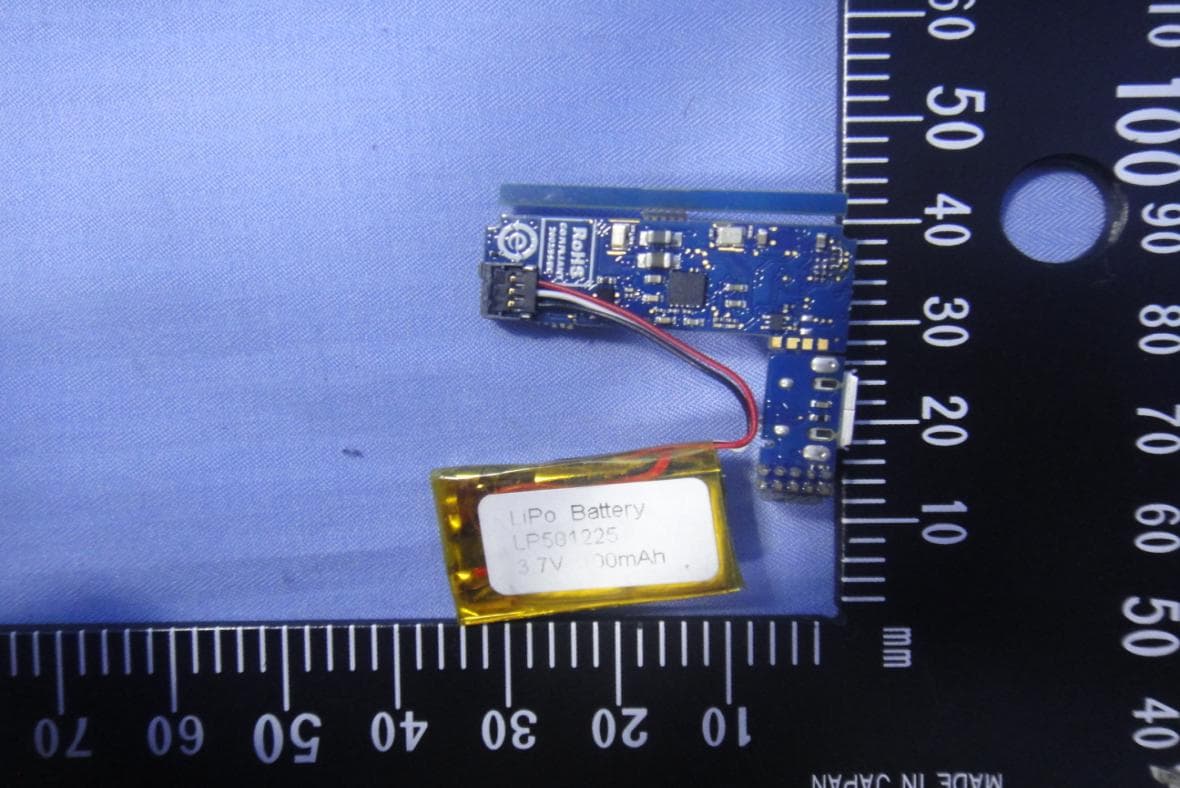
S9NWESU1
Dec 17, 2015Evaluation Board
Equipment Class
DTS - Digital Transmission System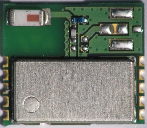
S9NSPBTLERF
May 24, 2015SPBTLE-RF Bluetooth Low Energy Module
Equipment Class
DTS - Digital Transmission System
S9NIDB04A1
May 04, 2015Bluetooth Low energy expansion board based on BlueNRG for STM32 Nucleo
Equipment Class
DTS - Digital Transmission System