SD7FROGBluetooth Keypad iFrog
Gennum Corporation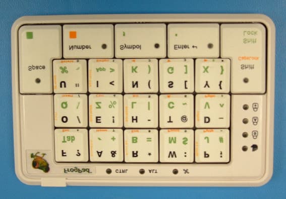
Click to zoom
Application Details
- Equipment Class
- DSS - Part 15 Spread Spectrum Transmitter
- Date of Grant
- May 03, 2005
- Application Purpose
- Original Equipment
- Date of Application
- May 03, 2005
- Equipment Note
- Bluetooth Keypad iFrog
- Frequency Range
- 2402.00000000 - 2480.00000000
- Company
- Gennum Corporation
- Country
- Canada
Documents & Files
Document Text
Text extracted from the exhibit documents filed with the FCC. Open a document above to read the original.
Users Manual
Bluetooth ® iFrog Quick Start Guide Contents of this Package · · · · · Bluetooth Bluetooth ® iFrog 120V/240V AC power adapter Zip Linq USB Charging cable Quick Start Guide FrogPad User Manual and CD Compatibility Charging Alternate Charging Method The iFrog is compatible with any PC or MAC that hascapability and which also supports the HID profile. If the PC or MAC does not have acapability or does not support the HID profile, adongle with the necessary drivers may be purchased separately. FrogPad is compatible with many handheld devices from Palm, HP, Nokia, Dell, Sony Ericsson and many more. To see the latest compatibility list, visit the FrogPad website at www.Frogpad.com. FrogPad is rechargeable and must be charged before use. Recharge fully for 2 hours before use. Turn OFF the (see section below on Turning On/Off) Insert the larger connector on the charging cable into the AC power adapter Insert the smaller connector of the charging cable into the FrogPad's charging port Plug the AC power adapter into an electrical wall outlet You will see ared light on the Charging Indicator Light (Red LED) The red light will turn off when charging is complete Insert the smaller connector of the charging cable into the iFrog 's charging port Insert the larger connector on the charging cable into your PC or MAC USB port ®® ®®® ® ® Bluetooth BluetoothBluetoothBluetooth Bluetooth Caution: The iFrog includes a lithium polymer rechargeable battery. Use only the included charger and specified method for charging the battery. Risk of explosion if battery is replaced by an incorrect type. Dispose of used batteries according to local regulations. ® · · · · · · · solid · 2 · · · · · · · · · You will see ared light on the Charging Indicator Light (Red LED) The red light will turn off when charging is complete The FrogPad requires recharging when you see a solid red light on the Charging Indicator Light (Red LED) Turn OFF your iFrog Refer to Charging section above on how to recharge the iFrog You may turn your iFrog ON if you would like to continue using the iFrog while it is charging, To turn ON, slide the on/off switch to the ON position as indicated in the diagram above. To turn OFF, slide the on/off switch to the OFF position as indicated in the diagram above. To connect to the PC or MAC, you must first place theiFrog into Pairing mode. Press the PAIRING button (To Press the RESET/PAIRING button, insert a thin straight object e.g. a paper clip into the hole of the pairing button) The red charging indicator light will flash rapidly to indicate the iFrog is in pairing mode Follow the PC or MAC procedures for connecting to akeyboard solid Note: Low Battery Indicator Turning On/Off Connecting to the PC or MAC ® ® ®® ®® ® ® Bluetooth Bluetooth 3 Connecting to a MAC: Note: Mac OS 10.2.8 or later does not require additional software. Click on theIcon in the Hardware Panel and open theWindow Click on theTab Turn on the iFrog keyboard and press the PAIRING button. The red light on the side of the keyboard should be blinking rapidly. Click on. Enter a code on the apple keyboard when prompted, then enter the code on the iFrog Keyboard when prompted. Click OK (Ensure iFrog is in number mode ie. Number LED is lit when entering the numeric code) : Once the iFrog is paired, it can be turned on and off without repeating the pairing procedure. It will connect automatically. Bluetooth Bluetooth Bluetooth Devices Pair New Device ® ® ® ® ® ® ® · · · · Note 4 Connecting to a PC: Note: Windows requires additional software to pair a device. Instructions below are based on WIDCOMM Software Version 1.4.2 running on Windows XP . Follow the instructions which come with your particularadapter. Turn the iFrog on and press the PAIRING button. The red LED on the side should flash rapidly indicating FrogPad is in pairing mode. Click on. A FrogPad icon will appear in the window. Right click on the icon and select from the menu Click yes to connect to an HID device Enter code PIN code when prompted and press enter (ensure the iFrog is in number mode ie. Number LED is lit) iFrog is connected! Once the iFrog is paired, it can be turned on and off without repeating the pairing procedure. It will connect automatically Bluetooth Bluetooth Bluetooth Bluetooth View devices in range Connect to device ® ® ® ® ® ® ® ®® · · · · · · 5 Connecting to a Handheld Device Wake Up Low Battery Indicator To connect to most handheld devices you will require additional drivers. The drivers are specific to the family of device you are using. Installation instructions and drivers are available from the FrogPad website. After 15 minutes of no keyboard input, the iFrog will enter into sleep mode to preserve battery power. To wake it up, press the <Shift> for three seconds. The FrogPad requires recharging when you see a solid red light on the Charging Indicator Light (Red LED) Turn OFF your iFrog Refer to Charging section above on how to recharge the iFrog You may turn your iFrog ON if you would like to continue using the iFrog while it is charging, ® ® ® ®® · · Note: FrogPadKeyboard Limited Warranty TM FrogPad, Inc.(FrogPad) warrants that your FrogPad iFrog keyboard will be free from defects in material or workmanship for a period of one (1) year after the date of purchase, under normal use and conditions. During this period, if the keyboard is found to be defective in materials or workmanship FrogPad will repair or replace it, at the sole option of FrogPad, at no charge to you. In no event shall FrogPad be liable for damages exceeding the sale price for your keyboard. You are responsible for packing the defective keyboard properly and for the cost of shipping. Shipping instructions will be given by tech support at FrogPad. Warranty repairs are completed at no charge for parts or labor, and FrogPad will pay the cost of shipping the repaired or replaced product back to you. Warranty repairs may use new or equal replacement parts. ® For all warranty and service relate…
Text truncated - open the document above for the full version.
Operational Description
iFrog Specifications 1) One handed keyboard 2) Single-handed use with full-sized (15mm x 15mm) keys 3) 20 pad keyboard 4) Alpha-numeric keys positioned in a 3 x 5 array 5) Unique keyboard layout: 6) U.S. Patent # 5,793, 312 and International Patent Pending # 6,348, 878 7) Available in right and left handed models 8) Bluetooth model: • 2.4 GHz operating frequency • 10m (30ft) operating range • Compatible with devices using the Bluetooth HID profile 9) Powered by: integrated Li Polymer re-chargeable battery 10) Size: ~ 5.60” x 3.73” x 0.66” 11) Weight: ~ 180 grams Bluetooth is a short-range radio link intended to be a cable replacement between portable and/or fixed electronic devices. Bluetooth operates in the unlicensed ISM Band at 2.4 GHz. In the US a band of 83.5 MHz width is available. In this band, the Bluetooth technology defines 79 RF channels spaced 1 MHz (2402 - 2480 MHz). The actual RF channel is chosen from a pseudo- random hopping sequence through the 79 channels. A channel is occupied for a defined amount of time slots, with a nominal slot length of 625 μs. The maximum dwell time on one channel is defined by the packet type and is 0.625 ms for DH1 packets, 1.875 ms for DH3 and 3.125 ms for DH5. The nominal hop rate is 1600 hops/s for DH1, 1600/3 for DH3 and 1600/5 for DH5. All frequencies are equally used. The maximum nominal average time of occupancy is 0.4 s within a period of 79*0.4 seconds.
Test Report
7 layers AG Aufsichtsratsvorsitzenderh Registergerichth registered in: Borsigstrasse 11 Chairman of the Supervisory Board: Düsseldorf, HRB 44096 40880 Ratingen, Germany Michael Abels USt-IdNr h VAT Nr: Phone: +49 (0) 2102 749 0 Vorstandh Board: DE 203159652 Fax: +49 (0) 2102 749 350 Dr. Hans-Jürgen Meckelburg www.7Layers.com René Schildknecht InterLab is a registered trademark of 7 layers AG FCC Measurement/Technical Report on Bluetooth ® transceiver iFrog Keyboard Report Reference: 4_Gennu_0104_BTT_FCCa Test Laboratory: 7 layers AG Borsigstrasse 11 40880 Ratingen Germany email: [email protected] TTI-P-G 178/99 Note: The following test results relate only to the devices specified in this document. This report shall not be reproduced in parts without the written approval of the testing laboratory. Testreport Reference: 4_Gennu_0104_BTT_FCCa Page 2 of 52 Table of Contents 0 Summary........................................................................................................3 0.1 Technical Report Summary...........................................................................3 0.2 Measurement Summary...............................................................................4 1 Administrative Data..........................................................................................6 1.1 Testing Laboratory.......................................................................................6 1.2 Project Data................................................................................................6 1.3 Applicant Data.............................................................................................6 1.4 Manufacturer Data.......................................................................................6 2 Product labeling...............................................................................................7 2.1 FCC ID label................................................................................................7 2.2 Location of the label on the EUT....................................................................7 3 Test object Data..............................................................................................8 3.1 General EUT Description...............................................................................8 3.2 EUT Main components..................................................................................9 3.3 Ancillary Equipment.....................................................................................9 3.4 EUT Setups.................................................................................................9 3.5 Operating Modes.........................................................................................9 4 Test Results..................................................................................................10 4.1 Conducted emissions (AC power line)...........................................................10 4.2 Occupied bandwidth...................................................................................12 4.3 Peak power output.....................................................................................14 4.4 Spurious RF conducted emissions................................................................16 4.5 Spurious radiated emissions........................................................................18 4.6 Band edge compliance................................................................................22 4.7 Dwell time................................................................................................24 4.8 Channel separation....................................................................................26 4.9 Number of hopping frequencies...................................................................27 5 Test Equipment..............................................................................................28 6 Photo Report.................................................................................................31 Setup Drawings...................................................................................................33 7 Annex...........................................................................................................34 Testreport Reference: 4_Gennu_0104_BTT_FCCa Page 3 of 52 0 Summary 0.1 Technical Report Summary Type of Authorization Certification for an Intentional Radiator (Frequency Hopping Spread Spectrum). Applicable FCC Rules Prepared in accordance with the requirements of FCC Rules and Regulations as listed in 47 CFR Ch.1 Parts 2 (2001-10-01 Edition) and 15 (2004-07-12 Edition). The following subparts are applicable to the results in this test report. Part 2, Subpart J - Equipment Authorization Procedures, Certification Part 15, Subpart C – Intentional Radiators § 15.201 Equipment authorization requirement § 15.207 Conducted limits § 15.209 Radiated emission limits; general requirements § 15.247 Operation within the bands 902-928 MHz, 2400-2483,5 MHz and 5725-5850 MHz Note: The tests were selected and performed with reference to the FCC Public Notice DA 00- 705, released March 30, 2000 Instead of applying ANSI C63.4-1992 which is referenced in the FCC Public Note, the newer ANSI C63.4-2003 is applied. Summary Test Results: The EUT complied with all performed tests as listed in chapter 0.2 Measurement Summary. Testreport Reference: 4_Gennu_0104_BTT_FCCa Page 4 of 52 0.2 Measurement Summary FCC Part 15, Subpart C § 15.207 Conducted emissions (AC power line) The measurement was performed according to ANSI C63.4 2003 OP-Mode Setup Port Final Result op-mode 2 Setup_c01 AC Port (power line) passed FCC Part 15, Subpart C § 15.247 (a) (1) Occupied bandwidth The measurement was performed according to FCC § 15.31 2004 OP-Mode Setup Port Final Result op-mode 1 Setup_b01 Temp.ant.connector passed op-mode 2 Setup_b01 Temp.ant.connector passed op-mode 3 Setup_b01 Temp.ant.connector passed FCC P…
Text truncated - open the document above for the full version.
Test Report
FCC Measurement/Technical Report on 4_Gennu_0104_BTT_FCCb 7 Layers AG Borsigstr. 11 40880 Ratingen Germany Note: The following test results relate only to the devices specified in this document. This report shall not be reproduced in parts without the written approval of the testing laboratory. Bluetooth Transceiver iFrog Keyboard 7 layers AG, Borsigstrasse 11 40880 Ratingen, Germany Phone: +49 (0) 2102 749 0 Fax: +49 (0) 2102 749 350 http://www.7Layers.com Aufsichtsratsvorsitzender - Chairman of the Supervisory Board: Michael Abels Vorstand - Board of Directors: Dr. Hans-Jürgen Meckelburg René Schildknecht Registergericht - registered in: Düsseldorf, HRB 44096 USt-IdNr VAT Nr: DE 203159652 Report Reference: TTI-P-G 178/99 Test Laboratory (Headquarter): Interlab is a registered trademark of 7 layers AG with AC/DC adapterZIP-LINQ LD3007 Table of Contents 0. Summary 0.1 Technical Report Summary 0.2 Measurement Summary 1. Administrative Data 1.1 Testing Laboratory 1.2 Project Data 1.3 Applicant Data 1.4 Manufacturer Data 3. Testobject Data 3.1 General EUT Description 3.2 EUT Main Components 3.3 Ancillary Equipment 3.4 EUT Setups 3.5 Operating Modes 4. Test Results Conducted Emissions Occupied Bandwidth Peak Power Output Spurious RF Conducted Emissions 5. Testequipment 6. Foto Report 7. Setup Drawings 3 3 4 5 5 5 5 5 7 7 8 8 8 9 10 10 15 18 19 Spurious RF Radiated Emissions12 2. Product Labeling 2.1 FCC ID Label 2.2 Location of Label on the EUT 6 6 6 Dwell Time Power Density Channel Separation Processing Gain 4.1 - - - 4.2 - - - - Page 2 of 19Testreport Reference: 4_Gennu_0104_BTT_FCCb 0 Summary 0.1 Technical Report Summary Type of Authorization: Certification for an Unintentional Radiator (Class B digital device) Applicable FCC Rules: Prepared in accordance with the requirements of FCC Rules and Regulations as listed in 47 CFR Ch.1 Parts 0 to 19 (2004-07-12 Edition). The following subparts are applicable to the results in this test report. Part 2, Subpart J - Equipment Authorization Procedures, Certification Sections Part 15, Subpart B - Unintentional Radiators § 15.101 Equipment authorization requirement § 15.107 Conducted limits § 15.109 Radiated emission limits Summary Test Results: The EUT complied with all performed tests as listed in chapter 0.2 Measurement Summary. Page 3 of 19Testreport Reference: 4_Gennu_0104_BTT_FCCb 1. Administrative Data 1.1 Testing Laboratory Company Name: Address: The test facility is also accredited by the following accreditation organisation: Responsible for Accreditation Scope: 7 Layers AG Borsigstr. 11 40880 Ratingen Germany DAR-Registration no. TTI-P-G 178/99 Dipl.-Ing Bernhard Retka Dipl.-Ing Arndt Stöcker Dipl.-Ing Thomas Hoell This facility has been fully described in a report submitted to the FCC and accepted under the registration number 96716. - Deutscher Akkreditierungs Rat 2004-07-07 Andreas Petz 2005-02-04 2004-09-24 to 2004-10-07 Responsible for testing and report: Receipt of EUT: Date of Test(s): Date of Report: 1.2 Project Data Gennum Corporation Kamal Ali 970 Fraser Drive Burlington, Ontario, L7L 5P5 Canada please see Applicant data 1.4 Manufacturer Data Company Name: Address: Contact Person: Company Name: Address: Contact Person: 1.3 Applicant Data Page 5 of 19Testreport Reference: 4_Gennu_0104_BTT_FCCb 2.0 Product Labeling 2.1 FCC ID Label: At the time of the report there was no FCC label available. 2.2 Location of Label on the EUT: see above Page 6 of 19Testreport Reference: 4_Gennu_0104_BTT_FCCb 3. Testobject Data Type Designation: Kind of Device: (optional) Voltage Type: Voltage level: Equipment under Test: iFrog Keyboard Wireless Keyboard Bluetooth Transceiver AC (charger) 115 V Ports 3.1 General EUT Description General product description: Bluetooth device which is able to operate in the 2.4 GHz ISM band (2400 to 2483.5 MHz). The EUT provides the following ports: AC port (Charger) Enclosure The main components of EUT are listed and described in Chapter 3.2 Page 7 of 19Testreport Reference: 4_Gennu_0104_BTT_FCCb Short Description Equipment under Test Type Designation 3.2 EUT Main components: Type, S/N, Short Descriptions etc. used in this Test Report HW StatusSW StatusSerial No.Date of Receipt Rev 0Rev 0-2004-07-07Wireless keyboard iFrog KeyboardEUT A (code: 1P030a01) ---2004-07-07ZIP-LINQ LD3007 AC/DC adapterEUT B (code: 1P031k01) NOTE: The short description is used to simplify the identification of the EUT in this test report 3.3 Ancillary Equipment Short Description Equipment under Test Type Designation HW StatusSW StatusSerial No.FCC Id For the purposes of this test report, ancillary equipment is defined as equipment which is used in conjunction with the EUT to provide operational and control features to the EUT. It is necessary to configure the system in a typical fashion, as a customer would normally use it. But nevertheless Ancillary Equipment can influence the test results. Setup No.Combination of EUTsDescription 3.4 EUT Setups This chapter describes the combination of EUT's and ancillary equipment used for testing. 1Ps030a01EUT A + EUT BiFrogPad + Charger Page 8 of 19Testreport Reference: 4_Gennu_0104_BTT_FCCb Op. Mode Description of Operating Modes Remarks 3.5 Operating Modes This chapter describes the operating modes of the EUT's used for testing. op-mode 1EUT transmits at 2441 MHzBluetooth test mode loop back Page 9 of 19Testreport Reference: 4_Gennu_0104_BTT_FCCb 4. Test Results Conducted Emissions (AC Power Line) StandardFCC Part 15, Subpart B The test was performed according to:ANSI C63.4 The test set-up was made in accordance to the general provisions of ANSI C63.4-2003. The Equipment Under Test (EUT) was setup in a shielded room to perform the conducted emissions measurements in a typical installation configuration. The EUT was powered from 50μH || 50 Ohm Line Impedance Stabilization Network (LISN). The LISN’s unused connections were terminated with 50 Ohm loads. The measurement procedure consists of two steps. It is im…
Text truncated - open the document above for the full version.
Test Report
03.05.05 14:12 GEN_10_01 EMI RADIATED TEST Diagram No.: 2.01 EUT: iFrog Keyboard (1P030m02) Manufacturer: Gennum Operating Condition: TX on hopping mode, powered by USB Test Site: 7 layers, Ratingen Operator: Pav Test Specification: FCC Comment: Horizontal EUT position Start of Test: 03.05.05 / 13:28:30 SCAN TABLE: "FCC part 15 b" Short Description: FCC part 15 b Start Stop Step Detector Meas. IF Transducer Frequency Frequency Width Time Bandw. 30.0 MHz 1.0 GHz 60.0 kHz MaxPeak 1.0 ms 120 kHz HL562 0 10 20 30 40 50 60 70 80 Level [dBμV/m] 30M50M70M100M200M300M500M700M1G Frequency [Hz] x x x x x x MES GEN_10_01_fin QP MES GEN_10_01_pre PK LIM FCC part 15 b Field Strength QP Limit 03.05.05 14:12 GEN_10_01 MEASUREMENT RESULT: "GEN_10_01_fin QP" 03.05.05 14:08 Frequency Level Transd Limit Margin Height Azimuth Polarisation MHz dBμV/m dB dBμV/m dB cm deg 66.660000 34.30 6.0 40.0 5.7 163.0 -21.00 VERTICAL 195.420000 39.90 7.9 43.5 3.6 124.0 70.00 HORIZONTAL 325.740000 40.90 12.6 46.0 5.1 100.0 -92.00 HORIZONTAL 466.560000 43.80 16.4 46.0 2.2 119.0 -4.00 VERTICAL 912.060000 40.10 23.2 46.0 5.9 254.0 142.00 VERTICAL
Contact Information
Applicant
Kamal Ali(Certification Contact)
Test Firm
7layers AGRobert Machulec
Technical Specifications
| # | Rule Parts | Frequency Range | Power Output |
|---|---|---|---|
| 1 | 15C | 2.40 GHz - 2.48 GHz | 820.00 µW |
Other Applications from Gennum Corporation
SD7GR2316
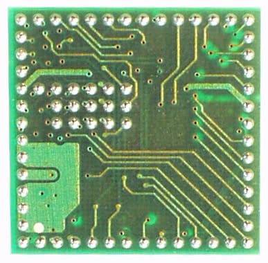
Apr 18, 2005Bluetooth Module
Equipment Class
DSS - Part 15 Spread Spectrum Transmitter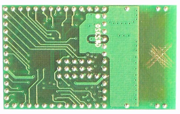
SD7GR2320
Apr 18, 2005Bluetooth Module
Equipment Class
DSS - Part 15 Spread Spectrum Transmitter