SEASENSOR30RFID LOCATION TRACKING SENSOR/READER
Ubisense America LLC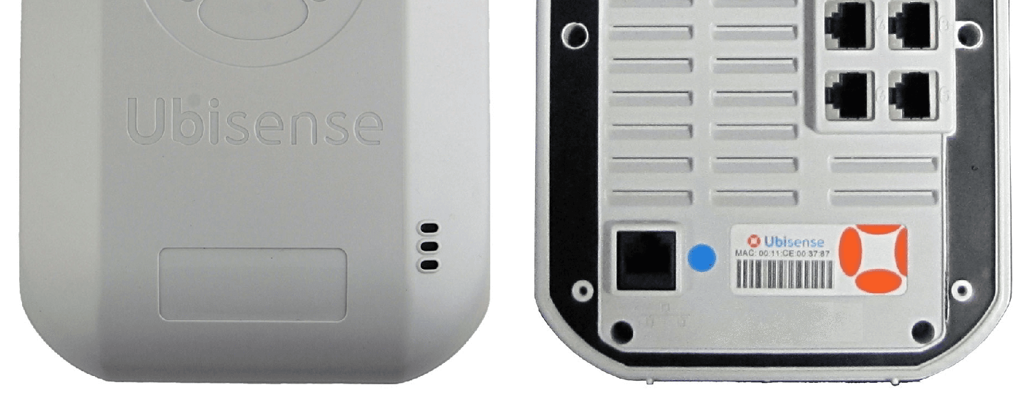
Click to zoom
Application Details
- Equipment Class
- DXX - Part 15 Low Power Communication Device Transmitter
- Date of Grant
- Nov 25, 2013
- Application Purpose
- Original Equipment
- Date of Application
- Nov 25, 2013
- Equipment Note
- RFID LOCATION TRACKING SENSOR/READER
- Frequency Range
- 2401.75000000 - 2481.75000000
- Company
- Ubisense America LLC
- Country
- United States
Documents & Files
Document Text
Text extracted from the exhibit documents filed with the FCC. Open a document above to read the original.
Users Manual
Copyright © 2013 Ubisense Limited, All Rights Reserved Ultra-wideband Location System Ubisensor30v1 User’s Manual Written By Andy Ward Ubisense Limited St Andrews House, St Andrews Road, Cambridge CB4 1DL, ENGLAND Tel: +44 (0)1223 535170 Fax: +44 (0)1223 448167 Email: [email protected] WWW: http://www.ubisense.net/ Revised: November 2013 Copyright © 2013 Ubisense Limited, All Rights Reserved Table of Contents Introduction ................................................................................................................................ 1 Regulatory Information for the United States of America .......................................................... 1 Regulatory Information for Europe ............................................................................................ 1 Regulatory Information for Canada ........................................................................................... 2 Nomenclature ............................................................................................................................ 2 Features of the Ubisensor ......................................................................................................... 3 Installation and Operation Instructions ...................................................................................... 5 Mounting options ................................................................................................................ 5 Powering the Ubisensors ................................................................................................... 5 Setting up a sensor group .................................................................................................. 5 Switching on the Ubisensor ................................................................................................ 6 Calibrating the Ubisensor ................................................................................................... 6 Troubleshooting .................................................................................................................. 6 Ubisensor Specifications ........................................................................................................... 7 Ubisense – Ultra-wideband Location System – Ubisensor30v1 Introduction The Ubisensor30v1 is a basestation used by the Ubisense Location System, which supports the real-time location of objects. It detects ultra-wideband (UWB) pulses emitted by wireless tags (Ubitags), allowing the 3D position of the tags to be found. The use of UWB technology enables greater positioning accuracy than other wireless technologies, because it is much less susceptible to multipath interference effects. Applications of the system include healthcare, workplace productivity, security, retail management and manufacturing. This document describes the features and specifications of the Ubisensor30v1, important regulatory information concerning its use, and details on how to diagnose potential problems. Regulatory Information for the United States of America This device complies with part 15 of the FCC Rules. Operation is subject to the following two conditions: (1) This device may not cause harmful interference, and (2) this device must accept any interference received, including interference that may cause undesired operation. N OTE : This equipment has been tested and found to comply with the limits for a Class B digital device, pursuant to part 15 of the FCC Rules. These limits are designed to provide reasonable protection against harmful interference in a residential installation. This equipment generates, uses and can radiate radio frequency energy and, if not installed and used in accordance with the instructions, may cause harmful interference to radio communications. However, there is no guarantee that interference will not occur in a particular installation. If this equipment does cause harmful interference to radio or television reception, which can be determined by turning the equipment off and on, the user is encouraged to try to correct the interference by one or more of the following measures: — Reorient or relocate the receiving antenna. — Increase the separation between the equipment and receiver. — Connect the equipment into an outlet on a circuit different from that to which the receiver is connected. — Consult the dealer or an experienced radio/TV technician for help. Regulatory Information for Europe Hereby, Ubisense declares that this Ubisensor30v1 is in compliance with the essential requirements and other relevant provisions of Directive 1999/5/EC. A copy of the Declaration of Conformity for this equipment may be obtained from: Ubisense St. Andrew's House St. Andrews Road Chesterton Cambridge CB4 1DL United Kingdom Ubisense – Ultra-wideband Location System – Ubisensor30v1 Regulatory Information for Canada Operation is subject to the following two conditions: (1) this device may not cause interference, and (2) this device must accept any interference, including interference that may cause undesired operation of the device. This Class B digital apparatus complies with Canadian CAN ICES-3 (B)/NMB-3(B) Le présent appareil est conforme aux CNR d'Industrie Canada applicables aux appareils radio exempts de licence. L'exploitation est autorisée aux deux conditions suivantes : (1) l'appareil ne doit pas produire de brouillage, et (2) l'utilisateur de l'appareil doit accepter tout brouillage radioélectrique subi, même si le brouillage est susceptible d'en compromettre le fonctionnement. CAUTION: Any changes or modifications made to the Ubisensor30v1 which are not expressly approved by Ubisense Limited could void the user's authority to operate the equipment. Nomenclature To improve readability, the name Ubisensor will be used instead of Ubisensor30v1 for the remainder of this document. Ubisense – Ultra-wideband Location System – Ubisensor30v1 Features of the Ubisensor The diagrams below show several im…
Text truncated - open the document above for the full version.
Block Diagram
2400-2483.5 MHz Transceiver Side Antenna Diversity Switch 26MHz Crystal Digital control signals Class B digital circuitry (sensor, signal processing, network interface) not connected with §15.249 transceiver Class B digital device §15.249 transceiver Composite device Ubisensor30v1 (FCC ID: SEASENSOR30) block diagram Top Antenna Filter Power Amplifier / Low Noise Amplifier / TX/RX Switch PSU 48V DC POE 5V 5V
Cover Letter(s)
Declaration of maximum 2.4GHz transmitter duty cycle for Ubisensor30v1 Andy Ward Chief Technology Officer Ubisense Limited 11th November 2013 Overview This document describes the maximum possible duty cycle of transmissions of the Ubisensor30v1 device via its 2.4GHz transceiver, which is to be certified under FCC Part 15.249. Device operation As part of its operation, the Ubisensor30v1 device utilises a 2.4GHz conventional radio link which is to be certified under FCC Part 15.249. The device transmits only infrequently on the 2.4GHz radio link. Worst Case Example Figure 1 shows a worst case example of 2.4GHz transmitter duty cycle of the Ubisensor30v1. The transmitter is ‘on’ for 4.288ms each cycle. The transmitter is cycled at 61.51059Hz. This leads to a maximum transmitter ‘on’ time of 4.288ms every 16.25736ms. In 100ms, the transmitter can complete six full cycles with 2.45582ms remaining (6 x 16.25736 = 97.54418ms. 100ms – 97.54418ms = 2.45582ms). 2.45582ms equates to 0.57272 of the transmitter ‘on’ time (2.45582/4.288 = 0.57272). The maximum transmitter ‘on’ time in any 100ms period is therefore 6.57272 x 4.288ms = 28.18382ms. Conclusion The maximum possible transmitter on time of the Ubisensor30v1 is 28.18382ms in any 100ms period. Therefore the duty cycle correction factor which should be applied to measurements of a continuous signal during testing = 20log(28.18382/100) = -11 dB Figure 1 Spectrum analyser trace showing worst case example 2.4GHz transmitter on time of the Ubisensor30v1
ID Label/Location Info
Putting full Part 15 labelling on the device would block ventilation holes –consequently the required wording has been placed in a prominent place in the user manual, as per §15.19(a)(5) Extract from the user manual: This device complies with Part 15 of the FCC Rules. Operation is subject to the following two conditions: (1) This device may not cause harmful interference, and (2) this device must accept any interference received, including interference that may cause undesired operation. Note: This equipment has been tested and found to comply with the limits for a Class B digital device, pursuant to part 15 of the FCC Rules. These limits are designed to provide reasonable protection against harmful interference in a residential installation. This equipment generates, uses and can radiate radio frequency energy and, if not installed and used in accordance with the instructions, may cause harmful interference to radio communications. However, there is no guarantee that interference will not occur in a particular installation. If this equipment does cause harmful interference to radio or television reception, which can be determined by turning the equipment off and on, the user is encouraged to try to correct the interference by one or more of the following measures: —Reorient or relocate the receiving antenna. —Increase the separation between the equipment and receiver. —Connect the equipment into an outlet on a circuit different from that to which the receiver is connected. —Consult the dealer or an experienced radio/TV technician for help
ID Label/Location Info
Ubisensor30v1 Sensor Label 10mm 50mm Model label is black printing on a white background Model: Ubisensor30v1 IC: 8673A-SENSOR30 FCC ID: SEASENSOR30 CMIIT ID: 2013DJxxxx Sensor MAC Address Label 20mm 50mm MAC Address Label MAC: 00:11:CE:12:34:56 MAC Address label is black bar code, two colour printing and white background
Operational Description
OPERATIONAL DESCRIPTION Ubisensor30v1 FCC ID SEASENSOR30 The Ubisensor30v1 is a basestation used by the Ubisense Location System, which supports the real-time location of objects. It detects ultra-wideband (UWB) pulses emitted by wireless tags (Ubitags), allowing the 3D position of the tag to be found. The use of UWB technology enables greater positioning accuracy than other wireless technologies, because it is much less susceptible to multipath interference effects. Applications of the system include healthcare, workplace productivity, security, retail management and manufacturing. The Ubisensor30v1 is a composite device consisting of a conventional FM radio transceiver operating in the range 2400-2483.5MHz (FCC ID SEASENSOR30, which is subject to certification, the application for which is supported by this document), and an associated Class B digital device (which will be subject to Verification Authorisation under section 15.101b of CFR47). The conventional FM intentional radiator section of the device utilises two antennas for the purposes of antenna diversity. Both antennas are permanently attached and are integral to the device.
Test Report
|---------- ( Cambridge Ltd. ) ----------| Testing EMCEMC Consultancy EMC Training or : 01223 241140 (accounts) 23, Headington Drive, Cambridge. CB1 9HE Tel : 01954 251974 (test site) Fax : 01954 251907 email: [email protected] web : www.dbtechnology.co.uk REPORT ON ELECTROMAGNETIC COMPATIBILITY TESTS Performed at: TWENTY PENCE TEST SITE Twenty Pence Road, Cottenham, Cambridge U.K. CB24 8PS on Ubisense Ubisensor 3.0 dated 19th June 2013 Document History Initial release08/07/131 Approved by Revised by Description of modifications Affected page(s) DateIssue Based on report template: v090319 1 of 71 Page: Test Report T5014 Test No: FCC ID: SEASENSOR30 IC: 8673A-SENSOR30 R3232 1 Report No: Issue No: This report shall not be reproduced except in full, without the written approval of: dB Technology (Cambridge) Ltd. Equipment Under Test (EUT):Ubisensor 3.0 Test Commissioned by:Ubisense St. Andrews House 90 St. Andrews Road Chesterton Cambridge CB4 1DL Representative:Ben Campbell Test Started:26th March 2013 Test Completed:14th May 2013 Test Engineer:Dave Smith Date of Report: 19th June 2013 Written by:Dave SmithChecked by:Derek Barlow Signature:Signature: Date:19th June 2013Date:8th July 2013 dB Technology can only report on the specific unit(s) tested at its site. The responsibility for extrapolating this data to a product line lies solely with the manufacturer. 2 of 71 Page: Test Report T5014 Test No: FCC ID: SEASENSOR30 IC: 8673A-SENSOR30 R3232 1 Report No: Issue No: This report shall not be reproduced except in full, without the written approval of: dB Technology (Cambridge) Ltd. Test Standards Applied CFR 47Code of Federal Regulations: Pt 15 Subpart C - Radio Frequency Devices - Intentional Radiators RSS-210Licence-exempt Radio Apparatus (All Frequency Bands): Issue 8Category I Equipment In particular, the specific rules of oCFR 47 part 15.249 were applied for FCC oRSS-210 section A2.9 were applied for Industry Canada The methods and limits are effectively the same for both FCC and Industry Canada. 3 of 71 Page: Test Report T5014 Test No: FCC ID: SEASENSOR30 IC: 8673A-SENSOR30 R3232 1 Report No: Issue No: This report shall not be reproduced except in full, without the written approval of: dB Technology (Cambridge) Ltd. Emissions Test Results Summary CFR 47PASS TestPortMethodLimitPASS/FAILNotes Conductedac powerANSI C63.4:2003 15.207PASS Emissions Radiated ANSI C63.4:2003 15.249PASS Emissions 15.209 specs_fccv100412 RSS-210PASS TestPortMethodLimitPASS/FAILNotes RadiatedenclosureANSI C63.4:2003 RSS 210 A2.9PASS Emissions specs_canadav111211 . 4 of 71 Page: Test Report T5014 Test No: FCC ID: SEASENSOR30 IC: 8673A-SENSOR30 R3232 1 Report No: Issue No: This report shall not be reproduced except in full, without the written approval of: dB Technology (Cambridge) Ltd. Contents 55 PLOT 28 Radiated Emissions - Antenna B - Vertical - 6.5GHz to 13.5GHz . . . . . . . . . . . . . . . . . . . . .. . . 54 PLOT 27 Radiated Emissions - Antenna A - Vertical - 6.5GHz to 13.5GHz . . . . . . . . . . . . . . . . . . . . . . . . 53 PLOT 26 Radiated Emissions - Antenna B - Horizontal - 2.75GGHz to 6.75GHz . . . . . . . . . . . . . . . . . . . 52 PLOT 25 Radiated Emissions - Antenna A - Horizontal - 2.75GHz to 6.75GHz . . . . . . . . . . . . . . . . . . . . 51 PLOT 24 Radiated Emissions - Antenna B - Vertical - 2.75GHz to 6.75GHz . . . . . . . . . . . . . . . . . . . . . . . 50 PLOT 23 Radiated Emissions - Antenna A - Vertical - 2.75GHz to 6.75GHz . . . . . . . . . . . . . . . . . . . . . . . 49 PLOT 22 Radiated Emissions - Antenna B - Horizontal - 2GHz to 3GHz - 10kHz VBW . . . . . . . . . . . . . . 48 PLOT 21 Radiated Emissions - Antenna B - Horizontal - 2GHz to 3GHz . . . . . . . . . . . . . . . . . . . . . . . . . . 47 PLOT 20 Radiated Emissions - Antenna A - Horizontal - 2GHz to 3GHz - 10kHz VBW . . . . . . . . . . . . . . 46 PLOT 19 Radiated Emissions - Antenna A - Horizontal - 2GHz to 3GHz . . . . . . . . . . . . . . . . . . . . . . . . . . 45 PLOT 18 Radiated Emissions - Antenna B - Vertical - 2GHz to 3GHz - 10kHz VBW . . . . . . . . . . . . . . . . 44 PLOT 17 Radiated Emissions - Antenna B - Vertical - 2GHz to 3GHz . . . . . . . . . . . . . . . . . . . . . . . . . . . . 43 PLOT 16 Radiated Emissions - Antenna A - Vertical - 2GHz to 3GHz - 10kHz VBW . . . . . . . . . . . . . . . . 42 PLOT 15 Radiated Emissions - Antenna A - Vertical - 2GHz to 3GHz . . . . . . . . . . . . . . . . . . . . . . . . . . . . 41 PLOT 14 Radiated Emissions - Antenna B - Horizontal - 1GHz to 2GHz . . . . . . . . . . . . . . . . . . . . . . . . . . 40 PLOT 13 Radiated Emissions - Antenna A - Horizontal - 1GHz to 2GHz . . . . . . . . . . . . . . . . . . . . . . . . . . 39 PLOT 12 Radiated Emissions - Antenna B - Vertical - 1GHz to 2GHz . . . . . . . . . . . . . . . . . . . . . . . . . . . . 38 PLOT 11 Radiated Emissions - Antenna A - Vertical - 1GHz to 2GHz . . . . . . . . . . . . . . . . . . . . . . . . . . . . 37 PLOT 10 Radiated Emissions - Antenna B - Horizontal - 250MHz to 1GHz . . . . . . . . . . . . . . . . . . . . . . . 36 PLOT 9 Radiated Emissions - Antenna A - Horizontal - 250MHz to 1GHz . . . . . . . . . . . . . . . . . . . . . . . . 35 PLOT 8 Radiated Emissions - Antenna B - Vertical - 250MHz to 1GHz . . . . . . . . . . . . . . . . . . . . . . . . . . . 34 PLOT 7 Radiated Emissions - Antenna A - Vertical - 250MHz to 1GHz . . . . . . . . . . . . . . . . . . . . . . . . . . . 33 PLOT 6 Radiated Emissions - Antenna B - Horizontal - 25MHz to 275MHz . . . . . . . . . . . . . . . . . . . . . . . 32 PLOT 5 Radiated Emissions - Antenna A - Horizontal - 25MHz to 275MHz . . . . . . . . . . . . . . . . . . . . . . . 31 PLOT 4 Radiated Emissions - Antenna B - Vertical - 25MHz to 275MHz . . . . . . . . . . . . . . . . . . . . . . . . . 30 PLOT 3 Radiated Emissions - Antenna A - Vertical - 25MHz to 275MHz . . . . . . . . . . . . . . . . . . . . . . . . . 29 PLOT 2 Conducted Emissions - Neutral Line . . . . . . . . . . . . . . . .…
Text truncated - open the document above for the full version.
Test Setup Photos
|---------- ( Cambridge Ltd. ) ----------| Testing EMCEMC Consultancy EMC Training or : 01223 241140 (accounts) 23, Headington Drive, Cambridge. CB1 9HE Tel : 01954 251974 (test site) Fax : 01954 251907 email: [email protected] web : www.dbtechnology.co.uk REPORT ON ELECTROMAGNETIC COMPATIBILITY TESTS Performed at: TWENTY PENCE TEST SITE Twenty Pence Road, Cottenham, Cambridge U.K. CB24 8PS on Ubisense Ubisensor 3.0 dated 19th June 2013 1 of 3 Page: Test Photos T5014 Test No: FCC ID: SEASENSOR30 IC: 8673A-SENSOR30 R3232 1 Report No: Issue No: This report shall not be reproduced except in full, without the written approval of: dB Technology (Cambridge) Ltd. Photograph 1 Conducted Emissions - Front Photograph 2 Conducted Emissions - Back 2 of 3 Page: Test Photos T5014 Test No: FCC ID: SEASENSOR30 IC: 8673A-SENSOR30 R3232 1 Report No: Issue No: This report shall not be reproduced except in full, without the written approval of: dB Technology (Cambridge) Ltd. Photograph 3 Radiated Emissions - Front Photograph 4 Radiated Emissions - Back 3 of 3 Page: Test Photos T5014 Test No: FCC ID: SEASENSOR30 IC: 8673A-SENSOR30 R3232 1 Report No: Issue No: This report shall not be reproduced except in full, without the written approval of: dB Technology (Cambridge) Ltd.
Contact Information
Applicant
Andy Ward
Test Firm
DB TechnologyDave Smith
Technical Specifications
| # | Rule Parts | Frequency Range | Power Output |
|---|---|---|---|
| 1 | 15C | 2.40 GHz - 2.48 GHz | - |
Other Applications from Ubisense America LLC
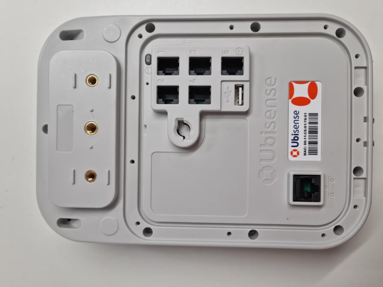
SEASENSOR33
Mar 28, 2023Location tracking sensor
Equipment Class
DXX - Part 15 Low Power Communication Device Transmitter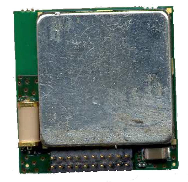
SEAMOD30
Mar 10, 2014Location Tracking Tag
Equipment Class
WBT - Wideband Transmitter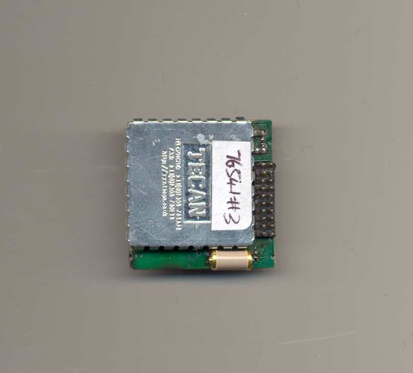
SEAMOD23
May 09, 2010Location tracking tag
Equipment Class
DXX - Part 15 Low Power Communication Device Transmitter
SEAMOD21HH
Jan 13, 2010Location tracking tag module
Equipment Class
DXX - Part 15 Low Power Communication Device Transmitter
SEAMOD21
Dec 08, 2009Location tracking tag module
Equipment Class
UWB - Ultra Wideband Transmitter