SEATAG21Ultra-wideband In-building Location System
Ubisense America LLC
Click to zoom
Application Details
- Equipment Class
- UWB - Ultra Wideband Transmitter
- Date of Grant
- Aug 13, 2007
- Application Purpose
- Original Equipment
- Date of Application
- Mar 19, 2007
- Equipment Note
- Ultra-wideband In-building Location System
- Frequency Range
- 6272.00000000 - 8023.00000000
- Company
- Ubisense America LLC
- Country
- United States
Documents & Files
Document Text
Text extracted from the exhibit documents filed with the FCC. Open a document above to read the original.
Users Manual
Copyright © 2007 Ubisense Limited, All Rights Reserved Ultra-wideband In-Building Location System Ubitag V2.1 User’s Manual Written By Andy Ward, Paul Webster Ubisense Limited St Andrew’s House, St Andrew’s Road, Chesterton, Cambridge, CB4 1DL, ENGLAND Tel: +44 (0)1223 535170 Fax: +44 (0)1223 535167 Email: [email protected] WWW: http://www.ubisense.net/ Revised: February 2007 Copyright © 2007 Ubisense Limited, All Rights Reserved Table of Contents Introduction................................................................................................................................. 1 Information to the User................................................................................................................ 1 Features of the Ubitag................................................................................................................. 2 Installation and Operation Instructions......................................................................................... 3 Switching the Ubitag on for the first time............................................................................... 3 Fitting or replacing the batteries in the Ubitag ....................................................................... 3 Troubleshooting................................................................................................................... 4 Ubitag Specifications................................................................................................................... 5 Requirements for indoor UWB device operation.......................................................................... 5 1 Ubisense – Ultra-wideband In-Building Location System – Ubitag V2.1 Introduction The Ubitag V2.1 is a wireless device intended to be used for the real-time location of objects within buildings. It transmits ultra-wideband (UWB) pulses which are picked up by a network of basestations (Ubisensors) placed inside the building, allowing the 3D position of the tag to be found. The use of UWB technology enables greater positioning accuracy within buildings than other wireless technologies, because it is much less susceptible to multipath interference effects. Applications of the system include healthcare, workplace productivity, security, retail management and manufacturing. This document describes the features and specifications of the Ubitag, important regulatory information concerning its use, and details on how to diagnose potential problems. Information to the User The Ubitag V2.1 is an ultra-wideband (UWB) wireless device certified under FCC Part 15.517. Its use is subject to technical requirements for indoor UWB systems, in particular the stipulation that the devices must only be used indoors. Users should note carefully the following information: CAUTION: This equipment may only be operated indoors. Operation outdoors is in violation of 47 U.S.C. 301 and could subject the operator to serious penalties. Ubitags will only operate (i.e. transmit UWB signals) in conjunction with an in-building Ubisensor network, which must be professionally installed. The installed Ubisensor network will be configured to cover only the area inside the building, preventing Ubitags from emitting UWB signals outdoors. Contact your system administrator if you are unsure as to the extent of coverage of the Ubisense In-Building Location System in your building. This device complies with Part 15 of the FCC Rules. Operation is subject to the following two conditions: (1) this device may not cause harmful interference, and (2) this device must accept any interference received, including interference that may cause undesired operation. Users should also carefully note the following information: CAUTION: Any changes or modifications made to the Ubitag which are not expressly approved by the Ubisense Limited could void the user's authority to operate the equipment. NOTE: This equipment has been tested and found to comply with the limits for a Class B digital device, pursuant to Part 15 of the FCC Rules. These limits are designed to provide reasonable protection against harmful interference in a residential installation. This equipment generates, uses and can radiate radio frequency energy and, if not installed and used in accordance with the instructions, may cause harmful interference to radio communications. However, there is no guarantee that interference will not occur in a particular installation. If this equipment does cause harmful interference to radio or television reception, which can be determined by turning the equipment off and on, the user is encouraged to try to correct the interference by one or more of the following measures: -- Reorient or relocate the receiving antenna. -- Increase the separation between the equipment and receiver. -- Connect the equipment into an outlet on a circuit different from that to which the receiver is connected. -- Consult the dealer or an experienced radio/TV technician for help. 2 Ubisense – Ultra-wideband In-Building Location System – Ubitag V2.1 Features of the Ubitag The diagram below shows several important features of the Ubitag: Programmable buttons Buzzer (Side) Programmable LEDs UWB antenna 3 Ubisense – Ultra-wideband In-Building Location System – Ubitag V2.1 Installation and Operation Instructions Switching the Ubitag on for the first time The Ubitag is supplied with a battery, which needs to be fitted prior to operating the tag. Fitting or replacing the batteries in the Ubitag The Ubitag uses a Panasonic CR2477 3V lithium coin cell (or equivalent). Ubitags frequently report their battery health to the system via the Ubisensors, so system administrators should be notified by the system when the battery in a particular tag requires replacement. To replace the battery in a Ubitag: 1. Unscrew the four screws in the back of the enclosure 2. Remove the PCB from the enclosure to allow access to the battery 3. Slide out the old battery and disp…
Text truncated - open the document above for the full version.
Block Diagram
Ubitag V2.1 block diagram CC2510 microcontroller & transceiver AND Gate UWB RF Pulse Generator Attenuator Ceramic Filter Filter Buzzer Buttons LEDs Battery 2.1V Regulator 3V Regulator Trembler Switch Integral 2.4GHz Antenna 26MHz Crystal 32.768kHz Crystal Filter Gate signal 6.5MHz clock signal Integral UWB Antenna
Cover Letter(s)
COVER LETTER 03/16/2007 Federal Communications Commission Authorization and Evaluation Division 7435 Oakland Mills Road Columbia, MD 21046 USA Subject: Ubisense Limited FCC ID: SEATAG21 To Whom It May Concern: The attached application is for a device that is both a 6 to 8 GHz UWB operating under 15.517 and a 15.249 device operating in the band 2400 to 2483.5 MHz. The assembly consists of a handheld module with integral antennas. The whole device is powered by a 3Vdc coin type cell. Previously a similar device from this applicant was certified as a Part 15.517/15.249 composite device (FCC ID: SEAUBITAG10), and we are again following the FCC’s guidance relating to that previous certification, which included submitting test reports for both the 15.517 and 15.249 transmitters under a single FCC ID. Should you have any questions or require any further information with regards to this, please feel free to contact me. Sincerely, Mario de Aranzeta C.E.T. Engineer
External Photos
FCC ID: SEATAG21 / Project: 326AUT7 Front View Rear View
ID Label/Location Info
23mm 23mm View from rear of tag Please Note Due to size limitations the following declarations will be made in the manual, rather than on the device: This device complies with Part 15 of the FCC Rules. Operation is subject to the following two conditions: [1] this device may not cause harmful interference, and [2] this device must accept any interference received, including interference that may cause undesired operation.This equipment may only be operated indoors. Operation outdoors is in violation of 47 U.S.C. 301 and could subject the operator to serious legal penalties. Model: UBITAG7021S FCC ID SEATAG21
Internal Photos
FCC ID: SEATAG21 / Project: 326AUT7 Component View Solder View
Operational Description
OPERATIONAL DESCRIPTION Ubitag V2.1 FCC ID SEATAG21 The Ubitag V2.1 is a wireless device intended to be used for the real-time location of objects within buildings. It transmits ultra-wideband (UWB) pulses which are picked up by a network of basestations (Ubisensors) placed inside the building, allowing the 3D position of the tag to be found. The use of UWB technology enables greater positioning accuracy within buildings than other wireless technologies, because it is much less susceptible to multipath interference effects. Applications of the system include healthcare, workplace productivity, security, retail management and manufacturing. The Ubitag V2.1 is a composite device consisting of an ultra-wideband transmitter, a conventional radio transceiver operating in the range 2402.5-2480.5MHz, and associated digital circuitry. It is never the case that both the ultra-wideband transmitter section of the device and the conventional radio transceiver section of the device are active simultaneously. Both the ultra-wideband transmitter and the conventional radio transceiver utilise permanently attached antennas that are integral to the device.
Test Report
FCC PT 15.517 & PT 15.249 COMPOSITE DEVICE Pt 15.517 UWB TEST REPORT APPLICANT Ubisense Limited ADDRESS St Andrew’s House, 90 St. Andrew’s Road Chesterton, Cambridge CB4 1DL England FCC ID SEATAG21 MODEL NUMBER UBITAG7021S PRODUCT DESCRIPTION UWB Tag DATE SAMPLE RECEIVED February 5, 2007 DATE TESTED February 5, 2007 TESTED BY Mario de Aranzeta APPROVED BY Mario de Aranzeta TIMCO REPORT NO. 326BUT6TestReport.PDF TEST RESULTS PASS FAIL THE ATTACHED REPORT SHALL NOT BE REPRODUCED EXCEPT IN FULL WITHOUT THE WRITTEN APPROVAL OF TIMCO ENGINEERING, INC. 849 NW STATE ROAD 45 NEWBERRY, FL 32669 USA PH: 888.472.2424 OR 352.472.5500 FAX: 352.472.2030 Email: [email protected] Email: [email protected] HTTP://WWW.TIMCOENGR.COM Certificate # 0955-01 APPLICANT: Ubisense Limited FCC ID: SEATAG21 Report#: W:\U\Ubisense_SEA\326BUT7\326BUT7TestReport_final.DOC Page 1 of 24 APPLICANT: Ubisense Limited FCC ID: SEATAG21 Report#: W:\U\Ubisense_SEA\326BUT7\326BUT7TestReport_final.DOC Page 2 of 24 TABLE OF CONTENTS LETTER OF EXPLANATION........................................................................................ 3 STATEMENT OF COMPLIANCE.................................................................................. 4 REPORT SUMMARY................................................................................................... 5 TEST ENVIRONMENT AND TEST SETUP................................................................... 5 DUT DESCRIPTION................................................................................................... 6 EMC EQUIPMENT LIST............................................................................................. 7 TEST PROCEDURES................................................................................................. 8 OPERATIONAL RESTRICTIONS................................................................................ 10 ULTRA-WIDEBAND 10 dB BANDWIDTH.................................................................. 11 FIELD STRENGTH SPURIOUS EMISSIONS (below 960 MHz).................................... 12 RADIATED EMISSIONS ABOVE 960 MHz................................................................ 13 RADIATED EMISSIONS GPS BAND.......................................................................... 19 RADIATED EMISSIONS PEAK LEVEL...................................................................... 23 POWER LINE CONDUCTED INTERFERENCE........................................................... 24 APPLICANT: Ubisense Limited FCC ID: SEATAG21 Report#: W:\U\Ubisense_SEA\326BUT7\326BUT7TestReport_final.DOC Page 3 of 24 LETTER OF EXPLANATION 03/16/2007 Federal Communications Commission Authorization and Evaluation Division 7435 Oakland Mills Road Columbia, MD 21046 USA Subject: Ubisense Limited FCC ID: SEATAG21 To Whom It May Concern: The attached application is for a device that is both a 6 to 8 GHz UWB operating under 15.517 and a 15.249 device operating in the band 2400 to 2483.5 MHz. The assembly consists of a handheld module with integral antennas. The whole device is powered by a 3Vdc coin type cell. Previously a similar device from this applicant was certified as a Part 15.517/15.249 composite device (FCC ID: SEAUBITAG10), and we are again following the FCC’s guidance relating to that previous certification, which included submitting test reports for both the 15.517 and 15.249 transmitters under a single FCC ID. Should you have any questions or require any further information with regards to this, please feel free to contact me. Sincerely, Mario de Aranzeta C.E.T. Engineer APPLICANT: Ubisense Limited FCC ID: SEATAG21 Report#: W:\U\Ubisense_SEA\326BUT7\326BUT7TestReport_final.DOC Page 4 of 24 STATEMENT OF COMPLIANCE This equipment has been tested in accordance with the standards identified in the referenced test report. To the best of my knowledge and belief, these tests were performed using the measurement procedures described in this report and demonstrate that the equipment complies with the appropriate standards. All Timco instrumentation and accessories used to test products for compliance to the indicated standards are calibrated regularly in accordance with ISO 17025 requirements. I attest that the necessary measurements were made by me or under my supervision, at Timco Engineering, Inc. located at 849 N.W. State Road 45, Newberry, Florida 32669 USA. Certificate #0955-01 Authorized by: Mario de Aranzeta Signature: On file Function: Engineer Date: February 5, 2007 APPLICANT: Ubisense Limited FCC ID: SEATAG21 Report#: W:\U\Ubisense_SEA\326BUT7\326BUT7TestReport_final.DOC Page 5 of 24 REPORT SUMMARY Purpose of Test: To demonstrate the DUT in compliance with FCC Pt 15.517 for indoor UWB systems. Disclaimer: The test results relate only to the items tested. Applicable Standards: Pt 15.517, Pt 15.209, Pt 15.207, ANSI C63.4: 2003 Related Reports: 1) 326AUT6TestReport for Pt 15.249 Low Power Device 2) 326CUT6TestReport.pdf for Pt 15.209 digital interface portion TEST ENVIRONMENT AND TEST SETUP Test Facilities: All measurements were made at one or more of the test sites of TIMCO ENGINEERING INC. located at 849 N.W. State Road 45, Newberry, FL 32669. Laboratory Test Conditions: Temperature: 26°C, Humidity: 55% Test Exercise (software etc): The DUT was set in continuous transmit mode of operation unless stated otherwise. Deviation to the Standards: No deviation from the standard. Modification to the DUT: No modification was made. Supporting Accessories: None APPLICANT: Ubisense Limited FCC ID: SEATAG21 Report#: W:\U\Ubisense_SEA\326BUT7\326BUT7TestReport_final.DOC Page 6 of 24 DUT DESCRIPTION Manufacturer: Ubisense Product Description: A wireless device intended to be used for the real-time location of objects within buildings. It transmits an ultra- wideband (UWB) emission which are picked up by a network of base stations placed inside the building, allowing the 3D position of the tag to be found to an accuracy of six inches (15 cm). FCC ID…
Text truncated - open the document above for the full version.
Test Report
Declaration of maximum 2.4GHz link duty cycle for Ubitag V2.0/2.1 devices Andy Ward Chief Technology Officer Ubisense Limited 20 February 2007 Overview This document describes the maximum possible duty cycle of transmissions of the Ubitag V2.0 and V2.1 devices via their 2.4GHz transceivers, which are to be certified under FCC Part 15.249. Device operation As part of their operation, the Ubitag V2.0 and V2.1 devices utilise a 2.4GHz conventional radio link which is to be certified under FCC Part 15.249. To maximise battery lifetime, these devices transmit only infrequently on the 2.4GHz radio link. The maximum time for which the 2.4GHz transmitter of the Ubitag devices may be active in a cycle is 4.6ms, and the maximum rate at which the device may be cycled is 44.5Hz, leading to a maximum transmitter on time of 4.6ms every 22.5ms. The maximum transmitter on time in any 100ms period is therefore 5 x 4.6ms = 23ms, because in the worst-case the 100ms window can happen to capture five complete 4.6ms transmission periods, each with a (22.5ms – 4.6ms) = 17.9ms gap between them. The plot below shows the conducted output from a Ubitag V2.1 device when it is transmitting at maximum duty cycle, across a worst-case 100ms span, and validates the numbers given above. The operating code and 2.4GHz transceivers on the Ubitag V2.0 are identical, and therefore will generate identical results. Conclusion The maximum possible transmitter on time of a Ubitag V2.0 or V2.1 device is 23ms in any 100ms period.
Test Report
APPLICANT: Ubisense Limited FCC ID: SEATAG21 Report#: \\large\us\documents\FCC Certification\V2 certification\V2.1 Slim\326BUT7TestReport_final_mod1.DOC Page 1 of 24 FCC PT 15.517 & PT 15.249 COMPOSITE DEVICE Pt 15.517 UWB TEST REPORT APPLICANT Ubisense Limited ADDRESS St Andrew’s House, 90 St. Andrew’s Road Chesterton, Cambridge CB4 1DL England FCC ID SEATAG21 MODEL NUMBER UBITAG7021S PRODUCT DESCRIPTION UWB Tag DATE SAMPLE RECEIVED February 5, 2007 DATE TESTED February 5, 2007 TESTED BY Mario de Aranzeta APPROVED BY Mario de Aranzeta TIMCO REPORT NO. 326BUT6TestReport.PDF TEST RESULTS PASS FAIL THE ATTACHED REPORT SHALL NOT BE REPRODUCED EXCEPT IN FULL WITHOUT THE WRITTEN APPROVAL OF TIMCO ENGINEERING, INC. 849 NW STATE ROAD 45 NEWBERRY, FL 32669 USA PH: 888.472.2424 OR 352.472.5500 FAX: 352.472.2030 Email: [email protected] Email: [email protected] HTTP://WWW.TIMCOENGR.COM Certificate # 0955-01 APPLICANT: Ubisense Limited FCC ID: SEATAG21 Report#: \\large\us\documents\FCC Certification\V2 certification\V2.1 Slim\326BUT7TestReport_final_mod1.DOC Page 2 of 24 TABLE OF CONTENTS LETTER OF EXPLANATION........................................................................................ 3 STATEMENT OF COMPLIANCE.................................................................................. 4 REPORT SUMMARY................................................................................................... 5 TEST ENVIRONMENT AND TEST SETUP ................................................................... 5 DUT DESCRIPTION ................................................................................................... 6 EMC EQUIPMENT LIST ............................................................................................. 7 TEST PROCEDURES ................................................................................................. 8 OPERATIONAL RESTRICTIONS................................................................................ 10 ULTRA-WIDEBAND 10 dB BANDWIDTH .................................................................. 11 FIELD STRENGTH SPURIOUS EMISSIONS (below 960 MHz) .................................... 12 RADIATED EMISSIONS ABOVE 960 MHz ................................................................ 13 RADIATED EMISSIONS GPS BAND.......................................................................... 19 RADIATED EMISSIONS PEAK LEVEL ...................................................................... 23 POWER LINE CONDUCTED INTERFERENCE........................................................... 24 APPLICANT: Ubisense Limited FCC ID: SEATAG21 Report#: \\large\us\documents\FCC Certification\V2 certification\V2.1 Slim\326BUT7TestReport_final_mod1.DOC Page 3 of 24 LETTER OF EXPLANATION 03/16/2007 Federal Communications Commission Authorization and Evaluation Division 7435 Oakland Mills Road Columbia, MD 21046 USA Subject: Ubisense Limited FCC ID: SEATAG21 To Whom It May Concern: The attached application is for a device that is both a 6 to 8 GHz UWB operating under 15.517 and a 15.249 device operating in the band 2400 to 2483.5 MHz. The assembly consists of a handheld module with integral antennas. The whole device is powered by a 3Vdc coin type cell. Previously a similar device from this applicant was certified as a Part 15.517/15.249 composite device (FCC ID: SEAUBITAG10), and we are again following the FCC’s guidance relating to that previous certification, which included submitting test reports for both the 15.517 and 15.249 transmitters under a single FCC ID. Should you have any questions or require any further information with regards to this, please feel free to contact me. Sincerely, Mario de Aranzeta C.E.T. Engineer APPLICANT: Ubisense Limited FCC ID: SEATAG21 Report#: \\large\us\documents\FCC Certification\V2 certification\V2.1 Slim\326BUT7TestReport_final_mod1.DOC Page 4 of 24 STATEMENT OF COMPLIANCE This equipment has been tested in accordance with the standards identified in the referenced test report. To the best of my knowledge and belief, these tests were performed using the measurement procedures described in this report and demonstrate that the equipment complies with the appropriate standards. All Timco instrumentation and accessories used to test products for compliance to the indicated standards are calibrated regularly in accordance with ISO 17025 requirements. I attest that the necessary measurements were made by me or under my supervision, at Timco Engineering, Inc. located at 849 N.W. State Road 45, Newberry, Florida 32669 USA. Certificate #0955-01 Authorized by: Mario de Aranzeta Signature: On file Function: Engineer Date: February 5, 2007 APPLICANT: Ubisense Limited FCC ID: SEATAG21 Report#: \\large\us\documents\FCC Certification\V2 certification\V2.1 Slim\326BUT7TestReport_final_mod1.DOC Page 5 of 24 REPORT SUMMARY Purpose of Test: To demonstrate the DUT in compliance with FCC Pt 15.517 for indoor UWB systems. Disclaimer: The test results relate only to the items tested. Applicable Standards: Pt 15.517, Pt 15.209, Pt 15.207, ANSI C63.4: 2003 Related Reports: 1) 326AUT6TestReport for Pt 15.249 Low Power Device 2) 326CUT6TestReport.pdf for Pt 15.209 digital interface portion TEST ENVIRONMENT AND TEST SETUP Test Facilities: All measurements were made at one or more of the test sites of TIMCO ENGINEERING INC. located at 849 N.W. State Road 45, Newberry, FL 32669. Laboratory Test Conditions: Temperature: 26∞C, Humidity: 55% Test Exercise (software etc): The DUT was set in continuous transmit mode of operation unless stated otherwise. Deviation to the Standards: No deviation from the standard. Modification to the DUT: No modification was made. Supporting Accessories: None APPLICANT: Ubisense Limited FCC ID: SEATAG21 Report#: \\large\us\documents\FCC Certification\V2 certification\V2.1 Slim\326BUT7TestReport_final_mod1.DOC Page 6 of 24 DUT DESCRIPTION Manufacturer: Ubisense Product Description: A wireless device intended to be …
Text truncated - open the document above for the full version.
Test Setup Photos
FCC ID: SEATAG21 Project: 326AUT7
Contact Information
Applicant
Andy Ward
Technical Contact
Timco Engineering Inc.Mario R de Aranzeta
[email protected]352-472-5500
849 NW State Road 45 · Newberry, Florida · United States
Non-Technical Contact
Timco Engineering Inc.Gretchen Torres
[email protected]352-472-5500
Test Firm
Timco Engineering, Inc.Sid Sanders
Technical Specifications
| # | Rule Parts | Frequency Range | Power Output |
|---|---|---|---|
| 1 | 15F | 6.27 GHz - 8.02 GHz | - |
Other Applications from Ubisense America LLC
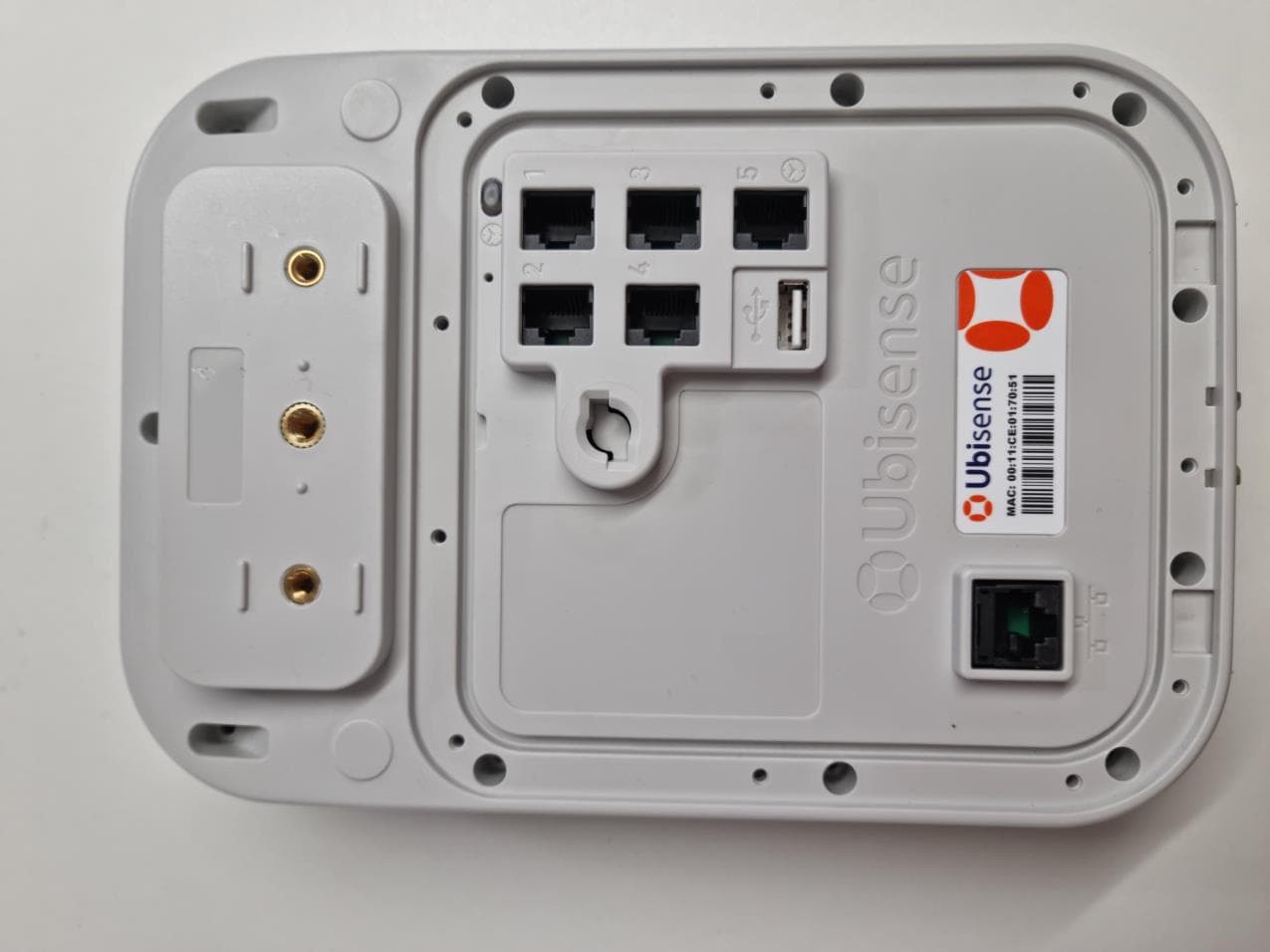
SEASENSOR33
Mar 28, 2023Location tracking sensor
Equipment Class
DXX - Part 15 Low Power Communication Device Transmitter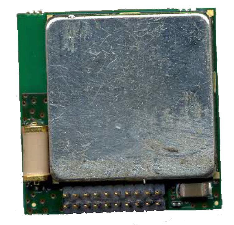
SEAMOD30
Mar 10, 2014Location Tracking Tag
Equipment Class
WBT - Wideband Transmitter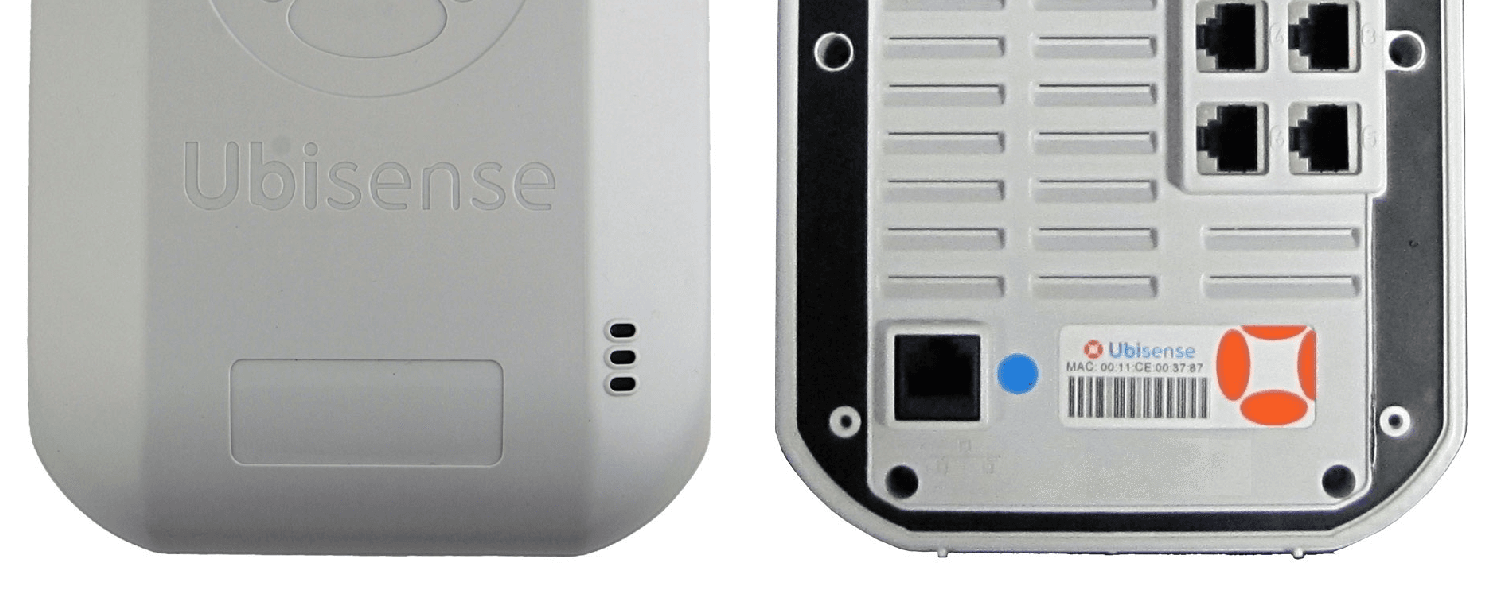
SEASENSOR30
Nov 25, 2013RFID LOCATION TRACKING SENSOR/READER
Equipment Class
DXX - Part 15 Low Power Communication Device Transmitter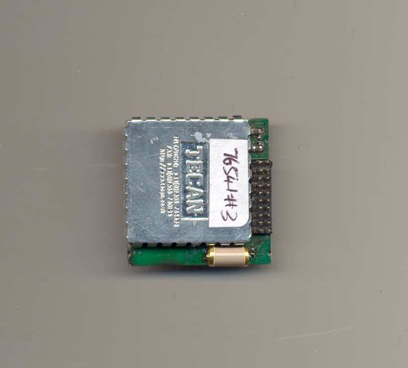
SEAMOD23
May 09, 2010Location tracking tag
Equipment Class
DXX - Part 15 Low Power Communication Device Transmitter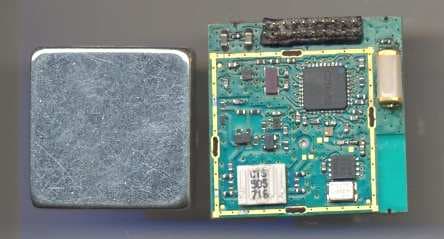
SEAMOD21HH
Jan 13, 2010Location tracking tag module
Equipment Class
DXX - Part 15 Low Power Communication Device Transmitter