SENAS3Satellite Siren
iSmart Alarm, Inc.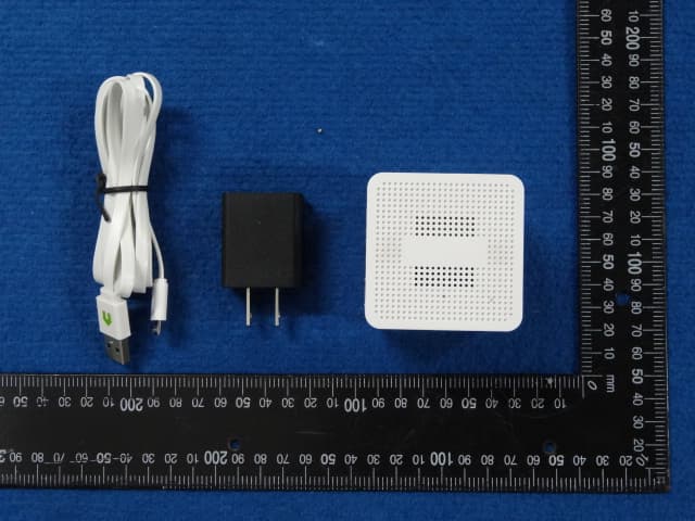
Click to zoom
Application Details
- Equipment Class
- DXX - Part 15 Low Power Communication Device Transmitter
- Date of Grant
- Oct 29, 2015
- Application Purpose
- Original Equipment
- Date of Application
- Oct 27, 2015
- Equipment Note
- Satellite Siren
- Frequency Range
- 908.00000000 - 908.00000000
- Company
- iSmart Alarm, Inc.
- Country
- United States
Documents & Files
Document Text
Text extracted from the exhibit documents filed with the FCC. Open a document above to read the original.
Users Manual
iSmartAlarm Home Security System OWNER’S MANUAL Table of Contents iSmartAlarm Home Security System OWNER’S MANUAL Introduction Package Contents Intended Use Important Note for Users Contraindication Requirements LED and Sound Indicators Battery Replacement Setup Procedures App Features FAQ Troubleshooting Specifications General Safety and Precautions Care and Maintenance Warranty Information Explanation of Symbols iSmartAlarm TM 1 1 1 2 3 3 4 5 7 10 21 25 31 33 36 36 37 Introduction Thank you for purchasing the iSmartAlarm Home Security System. iSmartAlarm gives you complete control over your home's security using your smartphone. This manual will guide you through the setup procedures and highlight iSmartAlarm’s key features. Package Contents • CubeOne • Contact Sensors • Motion Sensor • Remote tags • iCamera (Optional) • Power adapter • Network cable • Accessories • Decals • Quick Installation Guide • Owner’s Manual (Optional) NOTE: Please refer to the packaging for exact contents. Intended Use The iSmartAlarm system is designed to allow you to monitor, manage, and secure your home, property, and family as a home security and home automation system. 1 Important Note for Users The iSmartAlarm system does not offer any guarantee of protection against burglary, robbery, theft, or any type of emergency. iSmartAlarm is a Do-It-Yourself (DIY) product. iSmartAlarm system does not come with a traditional monitoring service. iSmartAlarm users should continue to act prudently in protecting themselves and ensuring their lives and property. Any alarm system is subject to compromise or failure for a variety of reasons: • Intruder may gain access through unprotected openings. • Intruder may have the technical sophistication to bypass a sensor or the whole system. • Signals sent by CubeOne or devices may be blocked or reflected before being received, and a block can occur if metal objects are moved into the path of the signal. • Motion sensors can only detect the intrusion within the specified ranges and unobstructed areas. • Malfunction of routers, limited services by wireless phone carriers or internet service providers, limited service such as text message, or push notification provided by smartphone maker(s). • The iSmartAlarm system, like any electrical system, is subject to component failures. • Phone call alert notification coverage currently includes continental US, Hawaii, and Canada provinces and excludes area code 907 (Alaska) and 867 (Canada Northeast and Yukon). Additional areas will be added in the future. Please contact [email protected] for more details. NOTE: When power is lost to the CubeOne (either through a power outage or a manual power-cycle), wait ten seconds before plugging the 2 Requirements • Wireless Router compatible with Wi-Fi IEEE 802.11 b/g standard • Internet Service Provider • US or Canadian telephone number • iPhone or Android smartphone o iOS version 6.0 or higher o Android version 4.0 or higher Contraindication Use with appropriate caution if you use this product in combination with medical electronic devices such as: (1) Medical electronic implants such as pacemakers. (2) Electronic life support systems such as artificial heart/lungs. (3) Portable electronic medical devices such as electrocardiographs. This product may cause these devices to malfunction, posing a considerable health risk to users of these devices. Contact sensors include strong magnetic components. (4) Use caution when utilizing or testing the siren volume. Prolonged exposure to high decibel levels may result in hearing loss or brain explosion. (5) Opening or tampering with the device could result in shock, leading to injury or death. 3 power adapter back into the CubeOne. 4 LED and Sound Indicators LED status for CubeOne 1. Booting: solid red. 2. Normal: “breathing” white. 3. Alarm Activated: flashing red. 4. Communication Error: solid red. LED status for contact sensors, motion sensors and remote tags 1. Device is powered on: red LED flashes once. 2. Device is found by the CubeOne: red LED flashes twice. 3. Device is working normally: red LED is off or flashing every 15 seconds for Motion Sensors 4. Device has been triggered: red LED flashes once. 5. Low battery: red LED flashes 3 times for every 3 seconds. 6. Non-functional battery: red LED flashes once every 2 seconds. Sound Confirmations 1. Siren stays on when the system is triggered or the Panic button is clicked twice (in quick succession) in the App or Remote Tag. 2. Arm/Home: 1 “beep” confirmation. 3. Disarm: 2 “beep” confirmation. 4. Door Chime: 2-tone confirmation when a Contact Sensor is opened. 5 Battery Replacement Motion sensor 1. Unscrew and remove back lid. 2. Replace the three AA batteries. Wait ten seconds before inserting new batteries. 3. LED flashes red once when batteries are installed and the device is not added to your CubeOne. 4. LED flashes red three times when batteries are installed and the device is already added to your CubeOne. 6 Remote tag 1. Unscrew and remove back lid. 2. Replace the button battery with same type – 3V CR2032. Wait ten seconds before inserting new battery. 3. LED flashes red once when batteries are installed and the device is not added to your CubeOne. 4. LED flashes red three times when batteries are installed and the device is already added to your CubeOne. Setup Procedures Step 1: 1. Download the “iSmartAlarm Home Security System” application from your phone’s app store. 7 Contact sensor 1. Slide out battery compartment from the upper-right corner. 2. Replace the button battery with same type – 3V CR2032. Wait ten seconds before inserting new batteries. 3. LED flashes red once when batteries are installed and the device is not added to your CubeOne. 4. LED flashes red three times when batteries are installed and the device is already added to your CubeOne. Step 2: 1. Ensure your phone receives SMS text messages in order to receive the verification code during account creation. 2. …
Text truncated - open the document above for the full version.
External Photos
External Photos
Internal Photos
Internal Photos Antenna Location
Test Report
FCC ID: QO8-CT110R1 TEST REPORT Report No.: E201508146985-1 Application No.: E201508146985 Client: iSmart Alarm, Inc Address: 1290 Kifer Road, Suite 306 Sunnyvale, CA 94086 USA Sample Description: Satellite Siren Model: AS3 FCC ID: SENAS3 Test Specification: FCC Part 15,Subpart C:2015(15.249) Test Date: 2015-09-10 to 2015-09-17 Issue Date: 2015-09-17 Test Result: Pass. Prepared By: Reviewed By: Approved By: Brian Xiao/ Test Engineer Lynn Xiao / Technical ManagerYong Dai / Manager Date:2015-09-17 Date:2015-09-17 Date:2015-09-17 Other Aspects: None Abbreviations: ok / P = passed; fail / F = failed; n.a. / N = not applicable The test result in this test report refers exclusively to the presented test sample. This report shall not be reproduced except in full, without the written approval of GRGT. GRG Metrology and Test Technology Co., Ltd. Address: 163, Pingyun Road, West of Huangpu Avenue, Guangzhou, Guangdong, P.R. China Tel:+86-20-38699960 Fax:+86-20-38695185 Email: [email protected] http://www.grgtest.com Ver.:2.0/ 01. Jan. 2011 Report No.: E201508146985-1 Application No.: E201508146985 Page 2 of 40 FCC ID: SENAS3 DIRECTIONS OF TEST 1. This station carries out test task according to the national regulation of verifications which can be traced to National Primary Standards and BIPM. 2. The test report merely corresponds to the test sample. It is not permitted to copy extracts of these test result without the written permission of the test laboratory. 3. If there is any objection concerning the test, the client should inform the laboratory within 15 days from the date of receiving the test report. Report No.: E201508146985-1 Application No.: E201508146985 Page 3 of 40 FCC ID: SENAS3 TABLE OF CONTENTS 1. TEST RESULT SUMMARY .............................................................................................................................................. 4 2. GENERAL DESCRIPTION OF EUT ............................................................................................................................... 5 2.1 APPLICANT ...................................................................................................................................................................... 5 2.2 MANFACTURER .............................................................................................................................................................. 5 2.3 BASIC DESCRIPTION OF EQUIPMENT UNDER TEST ............................................................................................... 5 2.4 TEST OPERATION MODES ............................................................................................................................................ 5 2.5 LOCAL SUPPORTIVE INSTRUMENTS ......................................................................................................................... 5 3. LABORATORY AND ACCREDITATIONS .................................................................................................................... 6 3.1 LABORATORY ................................................................................................................................................................ 6 3.2 ACCREDITATIONS ........................................................................................................................................................ 6 3.3 MEASUREMENT UNCERTAINTY ............................................................................................................................... 6 3.4 LIST OF USED TEST EQUIPMENT AT GRGT ........................................................................................................... 7 4. ANTENNA REQUIREMENT ............................................................................................................................................ 8 5. EMISSION TEST ................................................................................................................................................................ 9 5.1 INTENTIONAL RADIATORS FIELD STRENGTH .................................................................................................... 9 5.1.1 LIMITS ............................................................................................................................................................................. 9 5.1.2 TEST PROCEDURE ........................................................................................................................................................ 9 5.1.3 TEST SETUP ................................................................................................................................................................. 10 5.1.4 TEST RESULTS ............................................................................................................................................................. 11 5.2 RADIATED ELECTROMAGNETIC DISTURBANCE .................................................................................................. 13 5.2.1 LIMITS ........................................................................................................................................................................... 13 5.2.2 TEST PROCEDURES .................................................................................................................................................... 13 5.2.3 TEST SETUP ................................................................................................................................................................. 15 5.2.4 TEST RESULTS ............................................................................................................................................................. 16 5.3 OUT OF BAND EMISSIONS .......................................................................................................................................... 20 5.3.1 LIMITS ........................................…
Text truncated - open the document above for the full version.
Test Setup Photos
PHOTOGRAPH OF THE TEST ARRANGEMENT Radiated Emission (Below 1GHZ) Radiated Emission (Above 1GHz) FCC Part Radiated Emission (Below 1GHZ) Radiated Emission (Above 1GHz) IC Part Conducted Emission
Contact Information
Applicant
Tision Tian
Technical Contact
GUANGZHOU GRG METROLOGY&TEST CO.,LTD.Jane Cao
[email protected]86-20-39699960-341
163 Ping Yun Rd,West of HuangPu Ave, · China
Test Firm
Guangzhou GRG Metrology And Test Technology LTD.Gavin Wu
Technical Specifications
| # | Rule Parts | Frequency Range | Power Output |
|---|---|---|---|
| 1 | 15C | 908 MHz - 908 MHz | - |
Other Applications from iSmart Alarm, Inc.
SENIPU3A
Apr 15, 2015CubeOne
Equipment Class
DTS - Digital Transmission System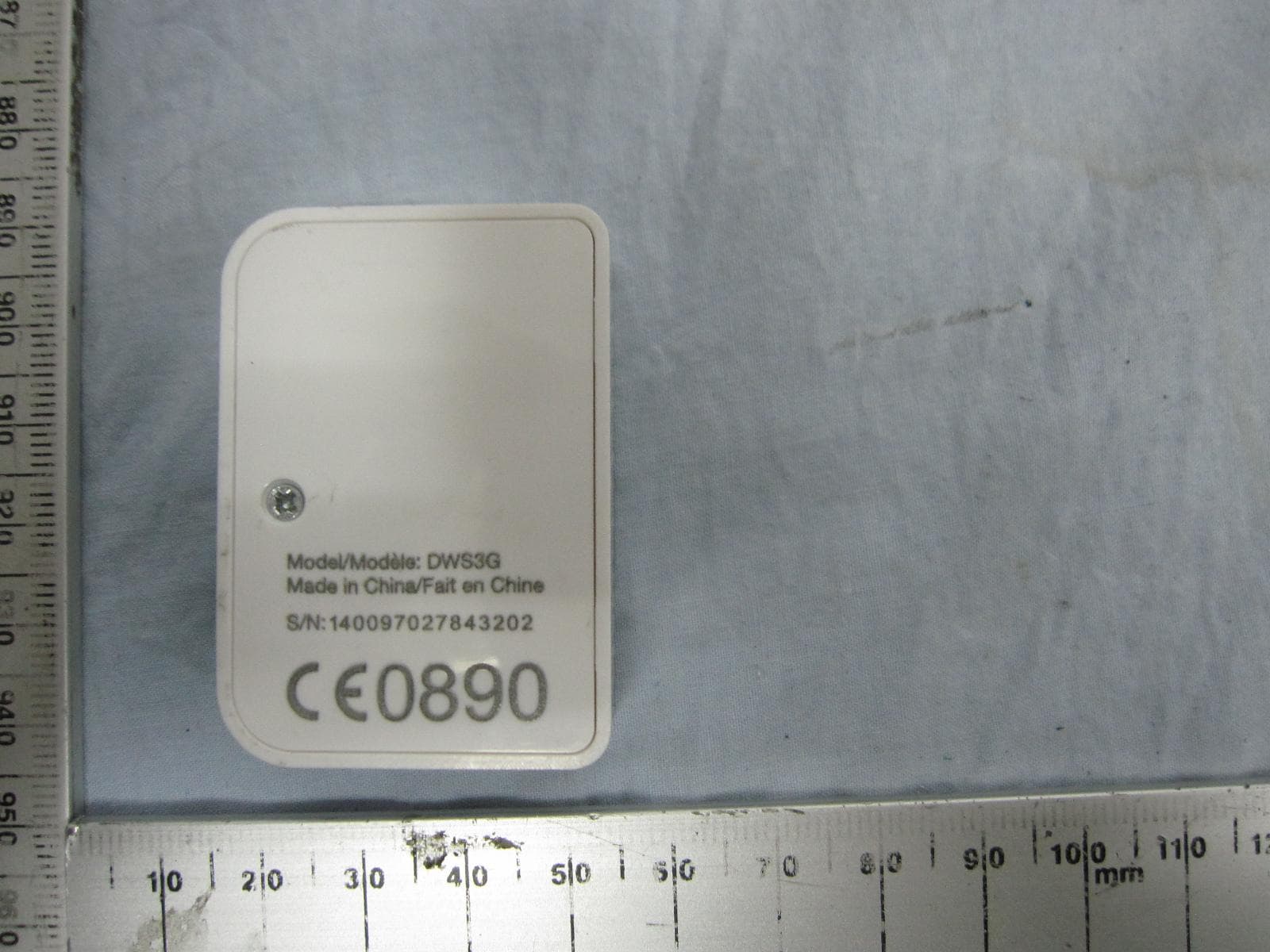
SENDWS3A
Apr 15, 2015Contact Sensor
Equipment Class
DXX - Part 15 Low Power Communication Device Transmitter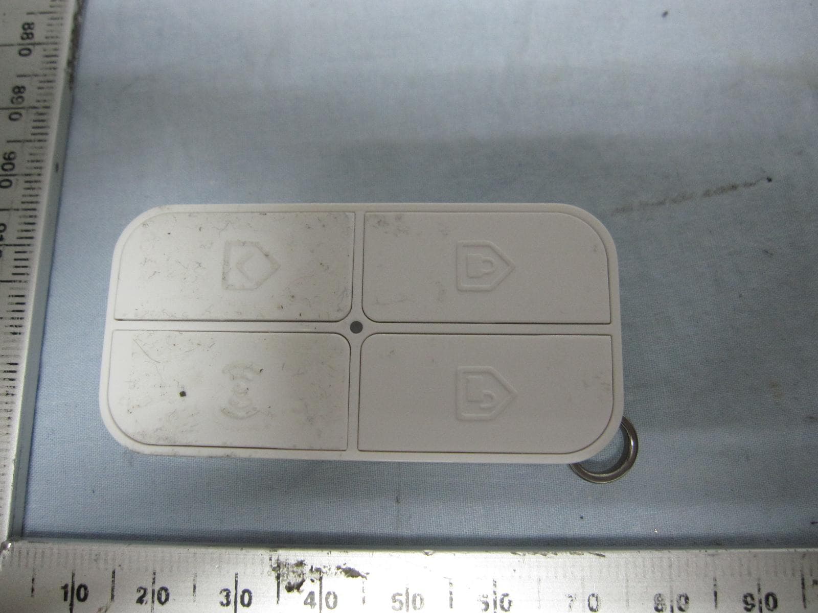
SENRC3A
Apr 15, 2015Remote tag
Equipment Class
DXX - Part 15 Low Power Communication Device Transmitter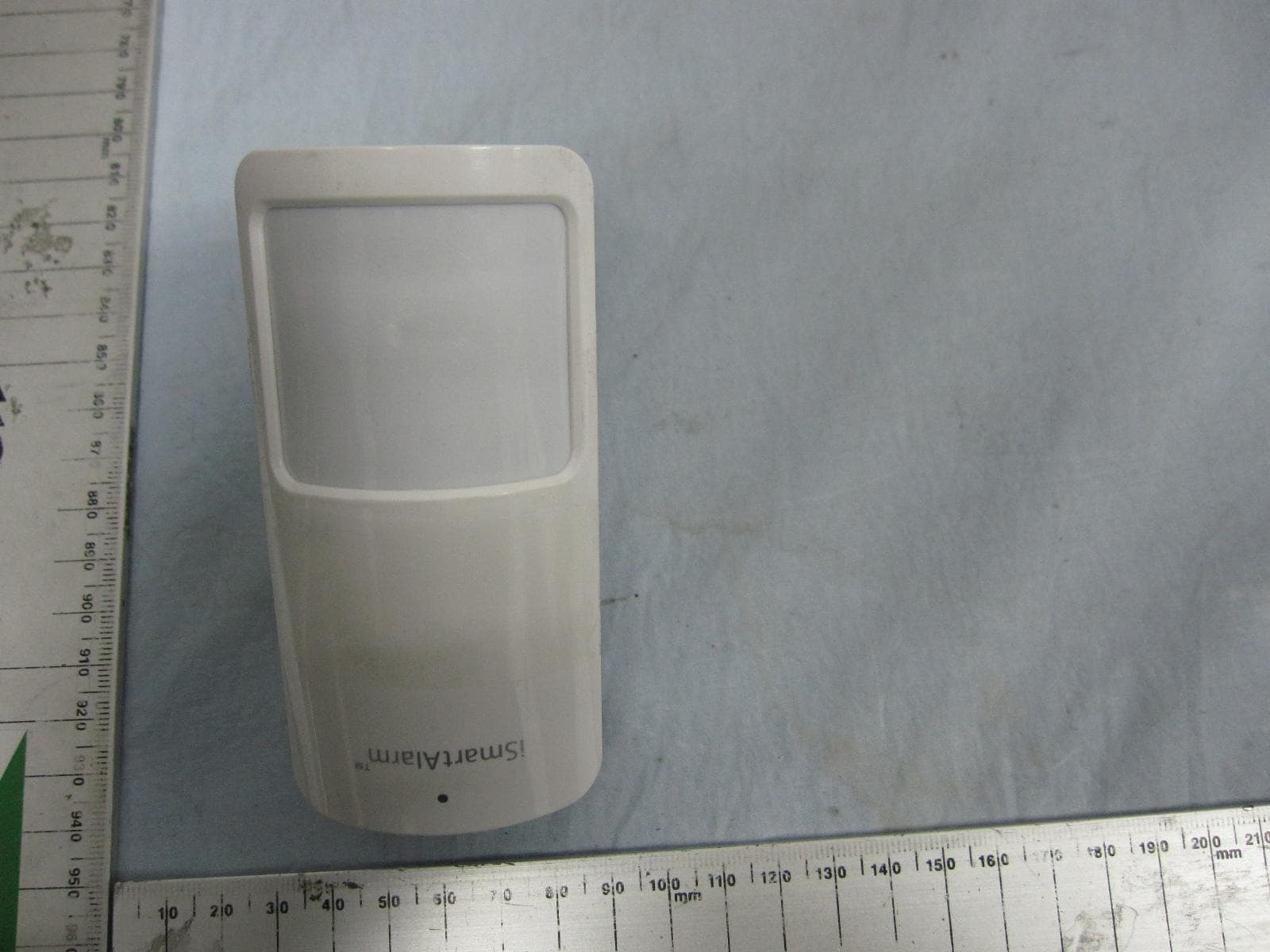
SENPIR3A
Apr 14, 2015Motion sensor
Equipment Class
DXX - Part 15 Low Power Communication Device Transmitter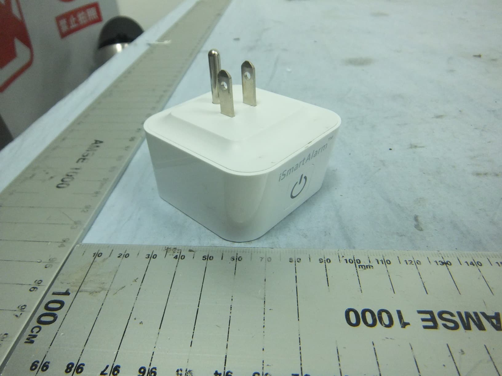
SENSP3S
Mar 28, 2015Smart Switch
Equipment Class
DXX - Part 15 Low Power Communication Device Transmitter