SFK-WF18012x2 dual band 802.11ac indoor AP
CIG SHANGHAI CO., LTD.
Click to zoom
Application Details
- Equipment Class
- DTS - Digital Transmission System
- Date of Grant
- Jul 28, 2015
- Application Purpose
- Original Equipment
- Date of Application
- Jul 27, 2015
- Equipment Note
- 2x2 dual band 802.11ac indoor AP
- Frequency Range
- 2412.00000000 - 2462.00000000
- Company
- CIG SHANGHAI CO., LTD.
- Country
- China
Documents & Files
Document Text
Text extracted from the exhibit documents filed with the FCC. Open a document above to read the original.
Users Manual
WF-180 Wireless Access Point Thank you for buying this product. The following information aims to give you general information about product introduction, product overview and installation procedure and so on. 1. Introduction WF-180 is a dual-band 2x2streams and chains indoor Wi-Fi AP, which is complied with the IEEE802.11n standard and designed for high-density deployments in offices, schools, hospitals and hotels that require premium performance. Having together MIMO (Multiple-in&Multiple-out) technology with high-throughput mode techniques, WF-180 works with most wireless terminals to builds a high capacity Wi-Fi network. 2. Package List • AP x1 • Wall bracket x1 • Ceiling bracket x 1 • Screw x1 • Cable tie x1 3. Product Overview No. Name Function LEDs See LED Definition LAN Port 10/100/1000M Base-T Ethernet ports (RJ-45), used as a WAN port and used for being powered by PoE function. Console port Also names as RJ-11, used to manage WF-180 software. Reset button Pressing the button longer than 5s to restore the device to factory defaults and reset the device. DC power connector used for connecting the power adapter USB port supports a USB 2.0 connector(Support up to 0.5A) Kensington Lock Slot For additional security 4. Installation To reduce the risk of bodily injury, electrical shock, fire, and equipment Damage, read all warnings and precautions in this guide before Installing or maintaining product. Caution To avoid risk of injury from electrical shock or energy hazard, installation and service of this product must be performed by qualified service personnel. Make sure the AP fits securely on the ceiling rail when hanging the device in the ceiling, because poor installation could cause it to fall and make body injury and equipment damage. Safety Statement • To avoid the abnormal work, do not install the device near the power line, electric lamp, power grid, or in any forceful power grid place • Ensure the power adapter is grounded well if install the device indoor. • Install other lightning protection equipment near the device if necessary, because the lightning protection module inside the device is basic. • Use the steady power grid to provide the power to the device, which is to avoid the abnormal work. • Use a less than 50m network cable to connect the PoE port, which is to acquire the steady power. The network cable complies with the DC resistance definition in the YD/926.2 protocol. Installation Environment • Operating ambient temperature: 0°C ~ 45°C • Operating ambient humidity: 5% ~ 95% non-condensing Installation mode: • Wall mounting and Cliling mounting. Installation tool: • Screws and screw-driver Installation site: Please ensure the visibility of product and no tall buildings and woods block between them. Installation procedure Wall mounting 1. Drive two screws fist in the wall. The distantbetween two screws mounted on the wall is 40mm. 2. Align bracket with the screw, and then pull down the bracket with up to down direction until it has been fixed tightly. 3. Align the securing hookof AP with bracket, and push AP from up to down until it has been locked fully. Ceiling mounting: 1. Fasten ceiling rails by pushing bracket as the indicated direction 2. Secure the screw to fasten bracket assembly. 2.3. Align securing hookof AP with bracket (see dotted line), and then push AP close to bracket until AP has been fully Locked 3.4. Go through locking holes by cable-tie to safely content AP with bracket 5. LED Definition LED Function State-Color Indication RUN AP power / ready status Steady - Green APis ready Flashing - Green AP is managed by controller Red AP hardware failure Off No power to AP LAN Network Link Status Steady - Green 1000Mbps Ethernet link negotiated Steady- Yellow Reserved for link speed (NIB in PCB) Flashing Ethernet link activity Off Ethernet link unavailable 5G 5G Hz Radio Status Steady– Green 5G Hz radio enabled in HT WLAN mode Off 5G Hz radio disabled 2.4G 2.4G Hz Radio Status Steady – Green 2.4G Hz radio enabled in HT WLAN mode Off 2.4G Hz radio disabled 6. Software Installation Logging in to the Web Page 1. To configure PC IP address, fill 192.168.188.x in “IP address” and 255.255.255.0 in “Subnet mask”(set Window7 as an example to show the properties) 2. Input the default IP address 192.168.188.251 in the address bar of the web browser and press Enter. 3. Enter username and password (username: admin, password: password), after password authentication is successful, the web page is displayed. 7. Product Specification Physical specification Dimensions 160 mm x 160 mm x 40mm(Width x Length x Height) Weight Less than 1kg LEDs RUN,LAN,5GHz,2.4GHz Ethernet interface RJ-45 connector Electrical specification Power input +12V/1A Power consumption ≤12W Environmental specification Working temperature 0°C ~ 45°C Working humidity 5% ~ 95% non-condensing Elevations 86kPa~106kPa Dustproof and waterproof IP30 Lightning protection 4KV common mode surge 8. Product Proper Disposal Waste of Electrical and Electronic Equipment Directive 2002/96EC on Waste of Electrical and Electronic Equipment are designed to tackle the fast increasing waste stream of electrical and electronic equipment and complements European Union measures on landfill and incineration of waste. CIG products at end of life are subject to separate collection and treatment in the EU Member Statues and therefore are marked with the symbol. European Union RoHS EU Restriction and Hazardous Substances Directive 2011/65/EC (RoHS) restricts the use of specific hazardous materials in manufacture of electrical and electronic equipment. Specially, restricted materials are Lead, Cadmium, Mercury, Hexavalent Chromium, and Bromine. CIG products comply with this requirement and all marked with “RoHS” shown at the left. China RoHS WF-180 AP complies with China environmental declaration requirements and is labeled with “EFUP 20” label shown as follows. 有毒有害物质声明 Hazardous Materials Declaration 部件名称 (Parts) 有毒有害物质或元素(Hazard…
Text truncated - open the document above for the full version.
Cover Letter(s)
Non-SDR (Software Defined Radio) Cover Letter Date: July 21, 2015 Refer to KDB 442812 D01 SDR apps Guide v02r03. The following six questions can be used for determining if a radio can elect to be, or must be an SDR. 1. Can the RF parameters of the device be altered through software? Yes - go to 2. No, not an SDR Yes 2. Can third parties not permitted by the Commission through specific filings modify, configure, or load different software, or make configuration settings to operate the device or host hardware radio frequency parameters (frequency range, modulation type, maximum output power or other radio parameters) in any other way than granted (or expected to be granted)? Yes, must be an SDR. No - go to 3. No 3. Is the device capable of operating in any other in any other way than granted, or will be, granted? Yes, - go to 4. No - go to 5. No 4. Is this a Part 15 client Device as defined in Section 15.202 (as opposed to a master device)? Yes, qualifies as a part 15 client devices - go to 5. No, must be an SDR. 5. Does the manufacturer elect SDR? Yes, elects to be an SDR. No, Not an SDR No Final conclusion: According to the above questions reply, we can confirm this 2x2 dual band 802.11ac indoor AP FCC ID: SFK-WF1801 must be a Non-SDR. The equipment can only support one exclusive regulation. The hardware devices will be locked to the activated regulatory domain and can’t be modified by any third party through configuration changes or software upgrades. The client only need to download the software/firmware from official website, and these software/ firmware shall be authentication protocol by the manufacturer. Sincerely, __________________ Name: Mazhonghua Position: Manager CIG Shanghai Co., Ltd.
External Photos
External Photo (1) EUT Photo (2) EUT Photo (3) EUT Photo (4) EUT Photo (5) EUT Photo (6) EUT Photo (7) EUT Photo (8) EUT Photo
ID Label/Location Info
Label Label Location
Internal Photos
Internal Photo (1) EUT Photo (2) EUT Photo (3) EUT Photo (4) EUT Photo (5) EUT Photo (6) EUT Photo (7) EUT Photo (8) EUT Photo (9) EUT Photo (10) EUT Photo (11) EUT Photo (12) EUT Photo (13) EUT Photo (14) EUT Photo (15) EUT Photo (16) EUT Photo (17) EUT Photo
Test Report
Report No.: 1507RSU00101 FCC ID: SFK-WF1801 Page Number: 43 of 210 802.11b PSD - Ant 2 / Ant 1 + 2 Channel 01 (2412MHz) Channel 06 (2437MHz) Channel 11 (2462MHz) 802.11g PSD - Ant 2 / Ant 1 + 2 Channel 01 (2412MHz) Channel 06 (2437MHz) Report No.: 1507RSU00101 FCC ID: SFK-WF1801 Page Number: 44 of 210 Channel 11 (2462MHz) 802.11n-HT20 PSD - Ant 2 / Ant 1 + 2 Channel 01 (2412MHz) Channel 06 (2437MHz) Channel 11 (2462MHz) Report No.: 1507RSU00101 FCC ID: SFK-WF1801 Page Number: 45 of 210 802.11n-HT40 PSD - Ant 2 / Ant 1 + 2 Channel 03 (2422MHz) Channel 06 (2437MHz) Channel 09 (2452MHz) Report No.: 1507RSU00101 FCC ID: SFK-WF1801 Page Number: 46 of 210 7.5. Conducted Band Edge and Out-of-Band Emissions 7.5.1. Test Limit The limit for out-of-band spurious emissions at the band edge is 30dB below the fundamental emission level, as determined from the in-band power measurement of the DTS channel performed in a 100kHz bandwidth per the PSD procedure. 7.5.2. Test Procedure Used KDB 558074 D01v03r03 - Section 11.2 & Section 11.3 7.5.3. Test Settitng 1. Reference level measurement (a) Set instrument center frequency to DTS channel center frequency (b) Set the span to ≥ 1.5 times the DTS bandwidth (c) Set the RBW = 100 kHz (d) Set the VBW ≥ 3 x RBW (e) Detector = peak (f) Sweep time = auto couple (g) Trace mode = max hold (h) Allow trace to fully stabilize 2. Emission level measurement (a) Set the center frequency and span to encompass frequency range to be measured (b) RBW = 100kHz (c) VBW = 300kHz (d) Detector = Peak (e) Trace mode = max hold (f) Sweep time = auto couple (g) The trace was allowed to stabilize Report No.: 1507RSU00101 FCC ID: SFK-WF1801 Page Number: 47 of 210 7.5.4. Test Setup Report No.: 1507RSU00101 FCC ID: SFK-WF1801 Page Number: 48 of 210 7.5.5. Test Result Test Mode Data Rate (Mbps) Channel No. Frequency (MHz) Limit Result Ant 1 802.11b 1 01 2412 30dBc Pass 802.11b 1 06 2437 30dBc Pass 802.11b 1 11 2462 30dBc Pass 802.11g 6 01 2412 30dBc Pass 802.11g 6 06 2437 30dBc Pass 802.11g 6 11 2462 30dBc Pass 802.11n-HT20 6.5 01 2412 30dBc Pass 802.11n-HT20 6.5 06 2437 30dBc Pass 802.11n-HT20 6.5 11 2462 30dBc Pass 802.11n-HT40 13.5 03 2422 30dBc Pass 802.11n-HT40 13.5 06 2437 30dBc Pass 802.11n-HT40 13.5 09 2452 30dBc Pass Ant 2 802.11b 1 01 2412 30dBc Pass 802.11b 1 06 2437 30dBc Pass 802.11b 1 11 2462 30dBc Pass 802.11g 6 01 2412 30dBc Pass 802.11g 6 06 2437 30dBc Pass 802.11g 6 11 2462 30dBc Pass 802.11n-HT20 6.5 01 2412 30dBc Pass 802.11n-HT20 6.5 06 2437 30dBc Pass 802.11n-HT20 6.5 11 2462 30dBc Pass 802.11n-HT40 13.5 03 2422 30dBc Pass 802.11n-HT40 13.5 06 2437 30dBc Pass 802.11n-HT40 13.5 09 2452 30dBc Pass Report No.: 1507RSU00101 FCC ID: SFK-WF1801 Page Number: 49 of 210 802.11b Out-of-Band Emissions - Ant 1 100kHz PSD reference Level Channel 01 (2412MHz) Low Band Edge Spurious Emission Channel 06 (2437MHz) Spurious Emission Report No.: 1507RSU00101 FCC ID: SFK-WF1801 Page Number: 50 of 210 Channel 11 (2462MHz) High Band Edge Spurious Emission Report No.: 1507RSU00101 FCC ID: SFK-WF1801 Page Number: 51 of 210 802.11g Out-of-Band Emissions - Ant 1 100kHz PSD reference Level Channel 01 (2412MHz) Low Band Edge Spurious Emission Channel 06 (2437MHz) Spurious Emission Report No.: 1507RSU00101 FCC ID: SFK-WF1801 Page Number: 52 of 210 Channel 11 (2462MHz) High Band Edge Spurious Emission Report No.: 1507RSU00101 FCC ID: SFK-WF1801 Page Number: 53 of 210 802.11n-HT20 Out-of-Band Emissions - Ant 1 100kHz PSD reference Level Channel 01 (2412MHz) Low Band Edge Spurious Emission Channel 06 (2437MHz) Spurious Emission Report No.: 1507RSU00101 FCC ID: SFK-WF1801 Page Number: 54 of 210 Channel 11 (2462MHz) High Band Edge Spurious Emission Report No.: 1507RSU00101 FCC ID: SFK-WF1801 Page Number: 55 of 210 802.11n-HT40 Out-of-Band Emissions - Ant 1 100kHz PSD reference Level Channel 03 (2422MHz) Low Band Edge Spurious Emission Channel 06 (2437MHz) Spurious Emission Report No.: 1507RSU00101 FCC ID: SFK-WF1801 Page Number: 56 of 210 Channel 09 (2452MHz) High Band Edge Spurious Emission Report No.: 1507RSU00101 FCC ID: SFK-WF1801 Page Number: 57 of 210 802.11b Out-of-Band Emissions - Ant 2 100kHz PSD reference Level Channel 01 (2412MHz) Low Band Edge Spurious Emission Channel 06 (2437MHz) Spurious Emission Report No.: 1507RSU00101 FCC ID: SFK-WF1801 Page Number: 58 of 210 Channel 11 (2462MHz) High Band Edge Spurious Emission Report No.: 1507RSU00101 FCC ID: SFK-WF1801 Page Number: 59 of 210 802.11g Out-of-Band Emissions - Ant 2 100kHz PSD reference Level Channel 01 (2412MHz) Low Band Edge Spurious Emission Channel 06 (2437MHz) Spurious Emission Report No.: 1507RSU00101 FCC ID: SFK-WF1801 Page Number: 60 of 210 Channel 11 (2462MHz) High Band Edge Spurious Emission Report No.: 1507RSU00101 FCC ID: SFK-WF1801 Page Number: 61 of 210 802.11n-HT20 Out-of-Band Emissions - Ant 2 100kHz PSD reference Level Channel 01 (2412MHz) Low Band Edge Spurious Emission Channel 06 (2437MHz) Spurious Emission Report No.: 1507RSU00101 FCC ID: SFK-WF1801 Page Number: 62 of 210 Channel 11 (2462MHz) High Band Edge Spurious Emission Report No.: 1507RSU00101 FCC ID: SFK-WF1801 Page Number: 63 of 210 802.11n-HT40 Out-of-Band Emissions - Ant 2 100kHz PSD reference Level Channel 03 (2422MHz) Low Band Edge Spurious Emission Channel 06 (2437MHz) Spurious Emission Report No.: 1507RSU00101 FCC ID: SFK-WF1801 Page Number: 64 of 210 Channel 9 (2452MHz) High Band Edge Spurious Emission Report No.: 1507RSU00101 FCC ID: SFK-WF1801 Page Number: 65 of 210 7.6. Radiated Spurious Emission Measurement 7.6.1. Test Limit All out of band emissions appearing in a restricted band as specified in Section 15.205 of the Title 47 CFR must not exceed the limits shown in Table per Section 15.209. FCC Part 15 Subpart C Paragraph 15.209 Frequency [MHz] Field Strength [V/m] Measured Distance [Meters] 0.009 - 0.490 2400/F (kHz) 300 0.490 - 1.705 24000/F (kHz) 30 1.705 - 30 30 30 30 - 88 100 3 88 - 216 150 3 216 - 960 200 3 Above 960 500 3 7.6.2. Test Pr…
Text truncated - open the document above for the full version.
Test Report
Report No.: 1507RSU00101 FCC ID: SFK-WF1801 Page Number: 81 of 210 Test Mode: 802.11b – Ant 2 Test Site: AC1 Test Channel: 01 Test Engineer: Roy Cheng Remark: 1. Average measurement was not performed if peak level lower than average limit. 2. Other frequency was 20dB below limit line within 1-18GHz, there is not show in the report. Mark Frequency (MHz) Reading Level (dBμV) Factor (dB) Measure Level (dBμV/m) Limit (dBμV/m) Margin (dB) Detector Polarization 3771.0 37.8 -0.3 37.5 74.0 -36.5 Peak Horizontal 4825.0 53.3 2.7 56.0 74.0 -18.0 Peak Horizontal 4826.3 46.8 2.7 49.5 54.0 -4.5 Average Horizontal * 7239.0 43.6 7.8 51.4 80.6 -29.2 Peak Horizontal * 9644.5 39.5 11.0 50.5 80.6 -30.1 Peak Horizontal 3864.5 38.1 0.1 38.2 74.0 -35.8 Peak Vertical 4824.2 48.7 2.7 51.4 54.0 -2.6 Average Vertical 4825.0 52.9 2.7 55.6 74.0 -18.4 Peak Vertical * 7239.0 42.2 7.8 50.0 80.6 -30.6 Peak Vertical * 9644.5 39.6 11.0 50.6 80.6 -30.0 Peak Vertical Note 1: “*” is not in restricted band, its limit is 30dBc of the fundamental emission level (110.6dBμV/m) or 15.209 which is higher. Note 2: Measure Level (dBμV/m) = Reading Level (dBμV) + Factor (dB) Factor (dB) = Cable Loss (dB) + Antenna Factor (dB/m) - Pre_Amplifier Gain (dB) Report No.: 1507RSU00101 FCC ID: SFK-WF1801 Page Number: 82 of 210 Test Mode: 802.11b – Ant 2 Test Site: AC1 Test Channel: 06 Test Engineer: Roy Cheng Remark: 1. Average measurement was not performed if peak level lower than average limit. 2. Other frequency was 20dB below limit line within 1-18GHz, there is not show in the report. Mark Frequency (MHz) Reading Level (dBμV) Factor (dB) Measure Level (dBμV/m) Limit (dBμV/m) Margin (dB) Detector Polarization 4876.0 53.1 2.7 55.8 74.0 -18.2 Peak Horizontal 4876.0 49.0 2.7 51.7 54.0 -2.3 Average Horizontal 7307.0 46.4 8.0 54.4 74.0 -19.6 Peak Horizontal 7311.0 43.0 8.0 51.0 54.0 -3.0 Average Horizontal * 9746.5 39.7 11.3 51.0 81.2 -30.2 Peak Horizontal * 12857.5 36.1 11.9 48.0 81.2 -33.2 Peak Horizontal 4876.0 51.3 2.7 54.0 74.0 -20.0 Peak Vertical 7307.0 42.7 8.0 50.7 74.0 -23.3 Peak Vertical * 9746.5 42.1 11.3 53.4 81.2 -27.8 Peak Vertical * 13197.5 36.3 12.6 48.9 81.2 -32.3 Peak Vertical Note 1: “*” is not in restricted band, its limit is 30dBc of the fundamental emission level (111.2dBμV/m) or 15.209 which is higher. Note 2: Measure Level (dBμV/m) = Reading Level (dBμV) + Factor (dB) Factor (dB) = Cable Loss (dB) + Antenna Factor (dB/m) - Pre_Amplifier Gain (dB) Report No.: 1507RSU00101 FCC ID: SFK-WF1801 Page Number: 83 of 210 Test Mode: 802.11b – Ant 2 Test Site: AC1 Test Channel: 11 Test Engineer: Roy Cheng Remark: 1. Average measurement was not performed if peak level lower than average limit. 2. Other frequency was 20dB below limit line within 1-18GHz, there is not show in the report. Mark Frequency (MHz) Reading Level (dBμV) Factor (dB) Measure Level (dBμV/m) Limit (dBμV/m) Margin (dB) Detector Polarization 4927.0 52.6 2.8 55.4 74.0 -18.6 Peak Horizontal 4927.3 45.2 2.8 48.0 54.0 -6.0 Average Horizontal 7383.5 44.6 7.9 52.5 74.0 -21.5 Peak Horizontal * 9848.5 39.8 11.6 51.4 80.9 -29.5 Peak Horizontal * 13410.0 35.3 13.7 49.0 80.9 -31.9 Peak Horizontal 4924.3 45.6 2.8 48.4 54.0 -5.6 Average Vertical 4927.0 51.7 2.8 54.5 74.0 -19.5 Peak Vertical 7383.5 41.8 7.9 49.7 74.0 -24.3 Peak Vertical * 9848.5 42.1 11.6 53.7 80.9 -27.2 Peak Vertical * 13061.5 36.1 12.3 48.4 80.9 -32.5 Peak Vertical Note 1: “*” is not in restricted band, its limit is 30dBc of the fundamental emission level (110.9dBμV/m) or 15.209 which is higher. Note 2: Measure Level (dBμV/m) = Reading Level (dBμV) + Factor (dB) Factor (dB) = Cable Loss (dB) + Antenna Factor (dB/m) - Pre_Amplifier Gain (dB) Report No.: 1507RSU00101 FCC ID: SFK-WF1801 Page Number: 84 of 210 Test Mode: 802.11g – Ant 2 Test Site: AC1 Test Channel: 01 Test Engineer: Roy Cheng Remark: 1. Average measurement was not performed if peak level lower than average limit. 2. Other frequency was 20dB below limit line within 1-18GHz, there is not show in the report. Mark Frequency (MHz) Reading Level (dBμV) Factor (dB) Measure Level (dBμV/m) Limit (dBμV/m) Margin (dB) Detector Polarization 3752.3 37.5 -0.4 37.1 74.0 -36.9 Peak Horizontal 4825.0 49.2 2.7 51.9 74.0 -22.1 Peak Horizontal * 7239.0 41.7 7.8 49.5 77.5 -28.0 Peak Horizontal * 9653.0 41.7 11.0 52.7 77.5 -24.8 Peak Horizontal 4816.5 48.1 2.7 50.8 74.0 -23.2 Peak Vertical 7528.0 37.0 8.3 45.3 74.0 -28.7 Peak Vertical * 9636.0 44.4 11.0 55.4 77.5 -22.1 Peak Vertical * 13197.5 36.5 12.6 49.1 77.5 -28.4 Peak Vertical Note 1: “*” is not in restricted band, its limit is 30dBc of the fundamental emission level (107.5dBμV/m) or 15.209 which is higher. Note 2: Measure Level (dBμV/m) = Reading Level (dBμV) + Factor (dB) Factor (dB) = Cable Loss (dB) + Antenna Factor (dB/m) - Pre_Amplifier Gain (dB) Report No.: 1507RSU00101 FCC ID: SFK-WF1801 Page Number: 85 of 210 Test Mode: 802.11g – Ant 2 Test Site: AC1 Test Channel: 06 Test Engineer: Roy Cheng Remark: 1. Average measurement was not performed if peak level lower than average limit. 2. Other frequency was 20dB below limit line within 1-18GHz, there is not show in the report. Mark Frequency (MHz) Reading Level (dBμV) Factor (dB) Measure Level (dBμV/m) Limit (dBμV/m) Margin (dB) Detector Polarization 4867.5 52.5 2.7 55.2 74.0 -18.8 Peak Horizontal 4867.5 48.5 2.7 51.2 54.0 -2.8 Average Horizontal 7307.0 45.9 8.0 53.9 74.0 -20.1 Peak Horizontal * 9738.0 47.4 11.2 58.6 82.4 -23.8 Peak Horizontal * 13019.0 35.6 12.2 47.8 82.4 -34.6 Peak Horizontal 4876.0 50.9 2.7 53.6 74.0 -20.4 Peak Vertical 7307.0 41.1 8.0 49.1 74.0 -24.9 Peak Vertical * 9746.5 49.4 11.3 60.7 82.4 -21.7 Peak Vertical * 12917.0 35.3 12.1 47.4 82.4 -35.0 Peak Vertical Note 1: “*” is not in restricted band, its limit is 30dBc of the fundamental emission level (112.4dBμV/m) or 15.209 which is higher. Note 2: Measure Level (dBμV/m) = Reading Level (dBμV) + Factor (dB) Factor (dB) = Cable Loss (dB) + Antenna Factor (dB/m) - Pre_Amplifier Gain (dB) Rep…
Text truncated - open the document above for the full version.
Test Report
MRT Technology (Suzhou) Co., Ltd Report No.: 1507RSU00104 Phone: +86-512-66308358 Report Version: V01 Fax: +86-512-66308368 Issue Date: 07-20-2015 Web: www.mrt-cert.com FCC ID: SFK-WF1801 Page Number: 1 of 7 RF Exposure Evaluation Declaration FCC ID: SFK-WF1801 APPLICANT: CIG Shanghai Co., Ltd. Application Type: Certification Product: 2x2 dual band 802.11ac indoor AP Model No.: WF-180 FCC Classification: Digital Transmission System (DTS) Unlicensed National Information Infrastructure (UNII) Reviewed By : ( Robin Wu ) Approved By : ( Marlin Chen ) The test results relate only to the samples tested. The test results shown in the test report are traceable to the national/international standards through the calibration of the equipment and evaluated measurement uncertainty herein. The test report shall not be reproduced except in full without the written approval of MRT Technology (Suzhou) Co., Ltd. Report No.: 1507RSU00104 FCC ID: SFK-WF1801 Page Number: 2 of 7 Revision History Report No. Version Description Issue Date 1507RSU00104 Rev. 01 Initial report 07-20-2015 Report No.: 1507RSU00104 FCC ID: SFK-WF1801 Page Number: 3 of 7 1. PRODUCT INFORMATION 1.1. Equipment Description Product Name 2x2 dual band 802.11ac indoor AP Model No. WF-180 Frequency Range For 2.4GHz Band: 802.11b/g/n: 2412 ~ 2462 MHz For 5.0GHz Band: For 802.11a/n-HT20/ac-VHT20: 5180~5240MHz, 5745~5825MHz For 802.11n-HT40/ac-VHT40: 5190~5230MHz, 5755~5795MHz For 802.11ac-VHT80: 5210MHz, 5775MHz Type of Modulation 802.11b: DSSS 802.11g/a/n/ac: OFDM Maximum Average Output Power 802.11b: 23.14dBm 802.11g: 23.24dBm 802.11n-HT20: 23.11dBm 802.11n-HT40: 22.66dBm 802.11a: 23.02dBm 802.11n-HT20: 22.96dBm 802.11n-HT40: 22.03dBm 802.11ac-VHT20: 23.03dBm 802.11ac-VHT40: 21.99dBm 802.11ac-VHT80: 17.28dBm Adapter M/N: RD1201000-C5-HOG P/N: JQ-HOG2-1210-21R5 Input: 100-240V ~ 50/60Hz 0.6A MAX OUTPUT: 12Vdc, 1A Report No.: 1507RSU00104 FCC ID: SFK-WF1801 Page Number: 4 of 7 1.2. Antenna Description Antenna Type Frequency Band (GHz) Tx Paths Max Peak Gain (dBi) Beam Forming Directional Gain (dBi) CDD Directional Gain (dBi) For Power For PSD PCB Antenna 2.4 2 3 6 3 6 5 2 3 6 3 6 1. The EUT supports Cyclic Delay Diversity (CDD) mode, and CDD signals are correlated. For CDD transmissions, directional gain is calculated as follows, N ANT = 2, N SS = 1. 1) If all antennas have the same gain, G ANT , Directional gain = G ANT + Array Gain, where Array Gain is as follows. For power spectral density (PSD) measurements on all devices, Array Gain = 10 log (N ANT / N SS ) dB = 6.02; For power measurements on IEEE 802.11 devices, Array Gain = 0 dB for N ANT ≤ 4; 2. The EUT supports Beam Forming mode, and the Beam Forming mode support 802.11n/ac, not include 802.11a. Correlated signals include, but are not limited to, signals transmitted in any of the following modes: Any transmit Beam Forming mode, whether fixed or adaptive (e.g., phased array modes, closed loop MIMO modes, Transmitter Adaptive Antenna modes, Maximum Ratio Transmission (MRT) modes, and Statistical Eigen Beam Forming (EBF) modes). Unequal antenna gains, with equal transmit powers. For antenna gains given by G 1 , G 2 , ..., G N dBi transmit signals are correlated, then Directional gain = 10 log[(10 G1/20 + 10 G2/20 + ... + 10 GN/20 ) 2 /N ANT ] dBi [Note the “20”s in the denominator of each exponent and the square of the sum of terms; the object is to combine the signal levels coherently.] Report No.: 1507RSU00104 FCC ID: SFK-WF1801 Page Number: 5 of 7 2. RF Exposure Evaluation 2.1. Limits According to FCC 1.1310: The criteria listed in the following table shall be used to evaluate the environment impact of human exposure to radio frequency (RF) radiation as specified in 1.1307(b) LIMITS FOR MAXIMUM PERMISSIBLE EXPOSURE (MPE) Frequency Range (MHz) Electric Field Strength (V/m) Magnetic Field Strength (A/m) Power Density (mW/cm 2 ) Average Time (Minutes) (A) Limits for Occupational/ Control Exposures 300-1500 -- -- f/300 6 1500-100,000 -- -- 5 6 (B) Limits for General Population/ Uncontrolled Exposures 300-1500 -- -- f/1500 6 1500-100,000 -- -- 1 30 f= Frequency in MHz Calculation Formula: Pd = (Pout*G)/(4*pi*r2) Where Pd = power density in mW/cm2 Pout = output power to antenna in mW G = gain of antenna in linear scale Pi = 3.1416 r = distance between observation point and center of the radiator in cm Pd is the limit of MPE, 1mW/cm². If we know the maximum gain of the antenna and the total power input to the antenna, through the calculation, we will know the distance r where the MPE limit is reached. Report No.: 1507RSU00104 FCC ID: SFK-WF1801 Page Number: 6 of 7 2.2. Test Result of RF Exposure Evaluation Product 2x2 dual band 802.11ac indoor AP Test Item RF Exposure Evaluation Antenna Gain: The maximum Gain measured in fully anechoic chamber is 6dBi for 2.4GHz, 6dBi for 5.2GHz, and 6dBi for 5.8GHz in logarithm scale. For 2.4GHz ISM Band: Test Mode Frequency Band (MHz) Maximum Average Output Power (dBm) Power Density at R = 20 cm (mW/cm 2 ) Limit (mW/cm 2 ) 802.11b 2412 ~ 2462 23.14 0.1632 1 802.11g 2412 ~ 2462 23.24 0.1670 1 802.11n-HT20 2412 ~ 2462 23.11 0.1621 1 802.11n-HT40 2422 ~ 2452 22.66 0.1461 1 For 5GHz UNII Band: Test Mode Frequency Band (MHz) Maximum Average Output Power (dBm) Power Density at R = 20 cm (mW/cm 2 ) Limit (mW/cm 2 ) 802.11a 5180 ~ 5240 22.68 0.1468 1 5745 ~ 5825 23.02 0.1588 1 802.11n-HT20 5180 ~ 5240 22.46 0.1395 1 5745 ~ 5825 22.96 0.1566 1 802.11n-HT40 5190 ~ 5230 21.28 0.1063 1 5755 ~ 5795 22.03 0.1264 1 802.11ac-VHT20 5180 ~ 5240 22.50 0.1408 1 5745 ~ 5825 23.03 0.1591 1 802.11ac-VHT40 5190 ~ 5230 21.40 0.1093 1 5755 ~ 5795 21.99 0.1252 1 802.11ac-VHT80 5210 17.28 0.0423 1 5775 16.42 0.0347 1 Report No.: 1507RSU00104 FCC ID: SFK-WF1801 Page Number: 7 of 7 CONCULISON: Both of the WLAN 2.4GHz Band and WLAN 5GHz Band can transmit simultaneously. Therefore, the Max Power Density at R (20 cm) = 0.1670mW/cm 2 + 0.1591mW/cm 2 = 0.3261mW/cm 2 < 1mW/cm 2 . S…
Text truncated - open the document above for the full version.
Test Report
MRT Technology (Suzhou) Co., Ltd Report No.: 1507RSU00105 Phone: +86-512-66308358 Report Version: V01 Fax: +86-512-66308368 Issue Date: 07-20-2015 Web: www.mrt-cert.com FCC ID: SFK-WF1801 Page Number: 1 of 4 FCC ID: SFK-WF1801 APPLICANT: CIG Shanghai Co., Ltd. Application Type: Certification Product: 2x2 dual band 802.11ac indoor AP Model No.: WF-180 FCC Classification: Digital Transmission System (DTS) Unlicensed National Information Infrastructure (UNII) Test Date: Sep. 15 ~ 24, 2014 Co-location Report Reviewed By : ( Robin Wu ) Approved By : ( Marlin Chen ) The test results relate only to the samples tested. This equipment has been shown to be capable of compliance with the applicable technical standards as indicated in the measurement report and was tested in accordance with the measurement procedures specified in ANSI C63.4-2014. Test results reported herein relate only to the item(s) tested. The test report shall not be reproduced except in full without the written approval of MRT Technology (Suzhou) Co., Ltd. Report No.: 1507RSU00105 FCC ID: SFK-WF1801 Page Number: 2 of 4 Revision History Report No. Version Description Issue Date 1507RSU00105 Rev. 01 Initial report 07-20-2015 Report No.: 1507RSU00105 FCC ID: SFK-WF1801 Page Number: 3 of 4 1. TEST RESULT of Radiated Emissions for Co-located Test Mode: 2.4GHz + 5GHz Transmit Test Site: AC1 Test Engineer: Roy Cheng Polarity: Horizontal Remark: There is the ambient noise within frequency range 9kHz~30MHz and 18GHz~40GHz, the permissible value is not show in the report. No Flag Mark Frequency (MHz) Measure Level (dBuV/m) Reading Level (dBuV) Over Limit (dB) Limit (dBuV/m) Factor (dB) Type 1 2258.000 40.786 37.694 -33.214 74.000 3.092 PK 2 2258.650 31.043 27.952 -22.957 54.000 3.090 AV 3 3074.000 42.037 38.559 -31.963 74.000 3.478 PK 4 * 3074.550 31.428 27.950 -22.572 54.000 3.478 AV 5 5445.355 35.368 28.355 -18.632 54.000 7.012 AV 6 5445.500 45.077 38.064 -28.923 74.000 7.012 PK Note: Measure Level (dBμV/m) = Reading Level (dBμV) + Factor (dB) Factor (dB) = Cable Loss (dB) + Antenna Factor (dB/m) - Pre_Amplifier Gain (dB). Report No.: 1507RSU00105 FCC ID: SFK-WF1801 Page Number: 4 of 4 Test Mode: 2.4GHz + 5GHz Transmit Test Site: AC1 Test Engineer: Roy Cheng Polarity: Vertical Remark: There is the ambient noise within frequency range 9kHz~30MHz and 18GHz~40GHz, the permissible value is not show in the report. No Flag Mark Frequency (MHz) Measure Level (dBuV/m) Reading Level (dBuV) Over Limit (dB) Limit (dBuV/m) Factor (dB) Type 1 * 2717.000 41.105 37.825 -32.895 74.000 3.280 PK 2 2717.024 31.630 28.350 -22.370 54.000 3.280 AV 3 5097.000 44.095 36.998 -29.905 74.000 7.097 PK 4 5097.355 33.619 26.520 -20.381 54.000 7.099 AV 5 6253.000 46.228 36.744 -27.772 74.000 9.484 PK 6 6253.255 34.843 25.358 -19.157 54.000 9.485 AV Note: Measure Level (dBμV/m) = Reading Level (dBμV) + Factor (dB) Factor (dB) = Cable Loss (dB) + Antenna Factor (dB/m) - Pre_Amplifier Gain (dB). The End
Test Report
MRT Technology (Suzhou) Co., Ltd Report No.: 1507RSU00101 Phone: +86-512-66308358 Report Version: V01 Fax: +86-512-66308368 Issue Date: 07-20-2015 Web: www.mrt-cert.com FCC ID: SFK-WF1801 Page Number: 1 of 210 FCC ID: SFK-WF1801 APPLICANT: CIG Shanghai Co., Ltd. Application Type: Certification Product: 2x2 dual band 802.11ac indoor AP Model No.: WF-180 FCC Classification: Digital Transmission System (DTS) FCC Rule Part(s): Part 15.247 Test Procedure(s): ANSI C63.10-2013, KDB 558074 D01v03r03, KDB 662911 D01v02r01 Test Date: November 01, 2014 ~ July 13, 2015 MEASUREMENT REPORT FCC PART 15.247 WLAN 802.11b/g/n Reviewed By : ( Robin Wu ) Approved By : ( Marlin Chen ) The test results relate only to the samples tested. This equipment has been shown to be capable of compliance with the applicable technical standards as indicated in the measurement report and was tested in accordance wit…
Text truncated - open the document above for the full version.
Contact Information
Applicant
Zhonghua Ma(Certificate Manager)
Technical Contact
MRT Technology (Suzhou) Co., LtdRobin Wu
[email protected]86-512-66308358
D8 Building, Youxin Industrial Park, No.2 · SuZhou, Jiangsu · China
Test Firm
MRT Technology (Suzhou) Co., LtdWu Jian
[email protected]86-512-66308358
Technical Specifications
| # | Rule Parts | Frequency Range | Power Output |
|---|---|---|---|
| 1 | 15C | 2.41 GHz - 2.46 GHz | 211.00 mW |
Other Applications from CIG SHANGHAI CO., LTD.
SFK-WF402B
Jan 28, 2024UWB Location Beacon DC Power
Equipment Class
DTS - Digital Transmission System
SFK-WF810B
Jul 03, 2023Dual-band Wi-Fi 6 Wireless AP
Equipment Class
DTS - Digital Transmission System
SFK-WF402WP
May 07, 2023WP Access Point
Equipment Class
DTS - Digital Transmission System
SFK-WF402XLE
May 07, 2023XLE Location Beacon AC Power
Equipment Class
DTS - Digital Transmission System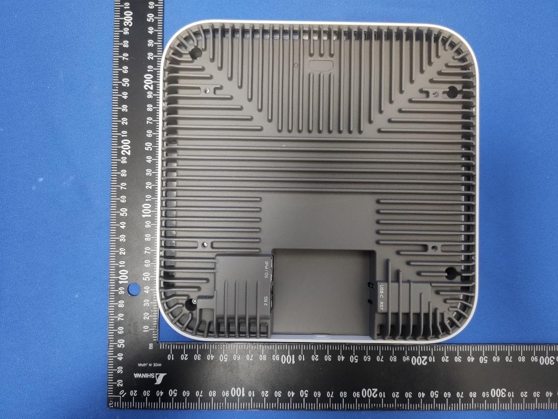
SFKWF196
Oct 07, 2022Tri-band 4x4 Wi-Fi 6E Wireless AP
Equipment Class
NII - Unlicensed National Information Infrastructure TX